
Related Manuals for RMG TME400-VMF


Summary of Contents for RMG TME400-VMF
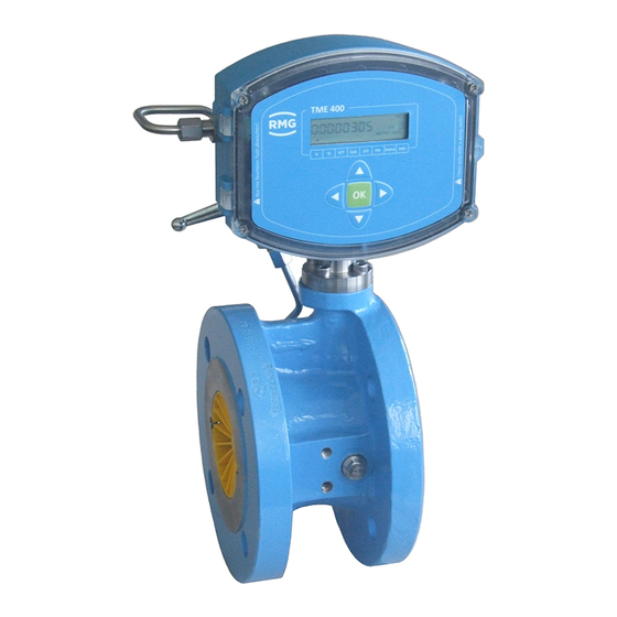
- Page 1 Turbine meter TME400-VM (..-VMF) OPERATING MANUAL Reliable Measurement of Gas Issued: 2018 September 6th Version: Firmware:...
- Page 2 Internet page: www.rmg.com. Created June 2018 1. Revision July 2018 2. Revision 2018 September 6th Document version and Document TME400VMF_manual_en_02 language version 2018 September 6th Language Manual TME400-VMF · EN02 · 2018 September 6th...
-
Page 3: Table Of Contents
USE OF GAS METERS FOR DIFFERENT GASES ............18 1.3.4.2. AREAS OF APPLICATION ...................... 19 1.4. WORKING PRINCIPLE OF THE TME400 ................19 1.4.1. INTEGRATING THE TURBINE METER INTO THE PIPELINE .......... 21 1.4.2. SEALS ..........................21 1.4.2.1. Manual TME400-VMF · EN02 · 2018 September 6th... - Page 4 EQUATIONS IN THE TME400 ....................54 4.3. VARIABLE DESCRIPTION ....................54 4.3.1. STANDARD FORMULA ....................... 54 4.3.2. COORDINATES IN CONTEXT .................... 55 4.3.3. VOLUME / METERS ......................55 4.3.3.1. FLOW RATE ........................57 4.3.3.2. Manual TME400-VMF · EN02 · 2018 September 6th...
- Page 5 OVERVIEW OF MATERIALS IN USE ..................74 5.2. ERROR MESSAGES ........................75 APPENDIX ............................76 MODBUS ............................76 DIMENSIONS ..........................84 TYPE PLATE ..........................88 SEAL DIAGRAMS ........................90 CERTIFICATES AND APPROVALS................... 91 Manual TME400-VMF · EN02 · 2018 September 6th...
-
Page 7: Introduction
The differences between the TME400-VM and TME400-VMF turbine meters are explained. If there is no explicit reference to differ- ences, the TME400 is superordinate for both versions of the turbine meter. -
Page 8: Purpose Of The Manual
(Volume Measurement) of the operating volume of non-aggressive gases and combustion fuels is used. TME400-VMF The TME400-VMF is a turbine gas meter that is used in custody- transfer applications (Fiscally). The designation TME400-VMF comprises all turbine meters. TME400-VC... -
Page 9: Symbols
The following notices are used: Danger This warning notice informs you of imminently threatening dangers that can arise due to misuse/operator error. If these situations are not avoided, death or severe injuries can occur. Manual TME400-VMF · EN02 · 2018 September 6th... -
Page 10: Working With The Device
Merely following the instructions may not suffice for correct operation. Always remain attentive and consider potential consequences. Manual TME400-VMF · EN02 · 2018 September 6th... - Page 11 Caution All notices in the manual must be observed. Use of the TME400 is only per- mitted in accordance with the specifications in the operating manual. RMG assumes no liability for damages arising due to disregard of the operating manual.
-
Page 12: Dangers During Commissioning
Install the device as specified in the operating manual. If the device is not installed as specified in the operating manual, there may be a risk that ade- quate explosion protection is not provided. The explosion protection is lost! Manual TME400-VMF · EN02 · 2018 September 6th... -
Page 13: Dangers During Maintenance And Repair
Dangers during maintenance and repair 1.2.4.3. Operating personnel The operating personnel use and operate the device in the scope of the intended use. Manual TME400-VMF · EN02 · 2018 September 6th... - Page 14 The TME400 must only be used as intended! (Chapter 1.3 Overview of versions). Prevent use of the TME400 as a potential climbing aid or use of attachments of the TME400 as potential handles! Manual TME400-VMF · EN02 · 2018 September 6th...
-
Page 15: Qualification Of Personnel
Risk assessment and minimization 1.2.5. According to assessment by qualified employees of RMG, the TME400 is subject to risks during its use. Risks can arise, for example, due to high pressures and occa- sionally due to pressures that are too low. Work outside of the permissible tempera- ture range can also lead to dangers. - Page 16 Every Ex signal circuit must be routed with a dedicated cable which must be guided through the appropriate PG screw coupling. Permanent installation of the intrinsically safe cable is mandatory. Manual TME400-VMF · EN02 · 2018 September 6th...
-
Page 17: Applicability Of The Manual
This manual describes the TME400. TME400 is generally only part of a complete system. The manuals of the other components of the system must be observed. If you find contradictory instructions, contact RMG and/or the manufacturers of the oth- er components. -
Page 18: Danger During Operation
Ensure safe packaging that absorbs light impact and vibrations is used for any further transport. Nevertheless, inform the transport company that all types of impact and vibrations should be avoided during transport. Manual TME400-VMF · EN02 · 2018 September 6th... -
Page 19: Scope Of Delivery
The scope of delivery can differ depending on the optional orders. The following is "normally” included in the scope of delivery: Part Quantity TME400-VM (or TME400-VMF) turbine meter 1 Lubricating oil bottle Optional Lubricating instructions Manual Test log Calibration certificate Manual TME400-VMF · EN02 · 2018 September 6th... -
Page 20: Disposal Of Packaging Material
Avoid extended periods of storage. After storage, inspect the device for damage and test for correct function. Contact the RMG service department to arrange for inspec- tion of the device after a storage period of longer than one year. For this purpose, return the device to RMG. -
Page 21: Overview Of Versions
The TME400-VM is used in non-custody- transfer applications. The TME400-VMF (MID) is the turbine meter for custody-transfer applications and has an equivalent function and operating method to the TME400-VM. The essential difference is the 2-channel measuring head version. It is used in custody-transfer applications. -
Page 22: Power Supply
Battery replace- ment is described in chapter 3.1.4 Battery replacement. In parameter G20 Date of last battery change the date of the last battery change is displayed (see chapter 4.3.3 Coordinates in context). Manual TME400-VMF · EN02 · 2018 September 6th... -
Page 23: Area Of Application
The EC type approval certificate is: TÜV 17 ATEX 207566 X IECEx TUN 18.0009 X The corresponding conformity certificates are provided in the annex. The RMG con- tact information is provided on the second and last page. Temperature ranges 1.3.4.1. -
Page 24: Use Of Gas Meters For Different Gases
2.93 Special The components of the gases must be within the concentration limits according to EN 437:2009 for test gases. Safe operation is guaranteed with these specified gases. Other gases on request. Manual TME400-VMF · EN02 · 2018 September 6th... -
Page 25: Areas Of Application
(Q ) is approximately proportional to the mean gas velocity and thus the flow rate. The number of rotations, therefore, is a measurement for the gas volume flowing through. Manual TME400-VMF · EN02 · 2018 September 6th... - Page 26 (number of pulses per m ). This oper- ating volume is shown in the display of the TME400. Manual TME400-VMF · EN02 · 2018 September 6th...
-
Page 27: Integrating The Turbine Meter Into The Pipeline
Integrating the turbine meter into the pipeline 1.4.2. Turbine meters from RMG are equipped with connecting flanges. For a secure con- nection, the connection dimensions of the flanges of the pipelines to be connected must match the connection dimensions of the flanges of the device. - Page 28 123.8 4" 123.8 154.0 6" 177.8 212.7 8" 228.6 266.7 10" 282.6 320.7 12" 339.7 377.8 16" 422.3 466.7 20" 530.2 581.0 24“ 631.8 682.6 Spiral seals (EN 12560-2 with centering ring) Manual TME400-VMF · EN02 · 2018 September 6th...
- Page 29 Ensure secure fastening/attachment of the TME400 during assembly in order to avoid crushing. Ensure that you keep your fingers (or other body parts) away from these openings and gaps when pulling the flanges together. Manual TME400-VMF · EN02 · 2018 September 6th...
-
Page 30: Screws
Other screw/flange variants were not tested. Malfunctions can occur with incorrect seals. Meter housing material 1.4.2.3. Cast steel or round steel material, depending on the pressure level and nominal di- ameter. Aluminum for the screw-type version. Manual TME400-VMF · EN02 · 2018 September 6th... -
Page 31: Installation
If there is pertubation (e.g. a gas pressure control device) upstream from the inlet pipe, a perforated plate straightener is also necessary. Perforated plate straightener according to ISO 5167-1 or the type RMG LP-35, which cause a pressure loss by a factor of 2.5 in comparison with the standard straightener, can be used. -
Page 32: Threshold Values
Ensure that there is no liquid remaining in the line above the meter after the hydrostatic testing. Threshold values 1.4.2.5. The following threshold values are recommended for maximum durability and the highest measuring accuracy: Manual TME400-VMF · EN02 · 2018 September 6th... - Page 33 Start-up screen (MW < 0.15 mm) • Filter • Meter protection perforated plates (Ø 3 - 4 mm) • Valves with control drive (flow change) • Check valves (pulsation, backflow) • Manual TME400-VMF · EN02 · 2018 September 6th...
-
Page 34: Technical Guideline G13
1 Introduction Technical guideline G13 1.4.2.6. The installation conditions for new systems according to TRG G13 and the facilitated installation conditions for RMG turbine meters are compared in the table below. Type of up- Installation Installation Comments stream per- conditions... -
Page 35: Standards / Guidelines
2 - 15 (c² / 2) Dynamic pressure loss p With the RMG turbine meters, these straighteners fulfill the requirements of technical guideline G 13 and are approved with approval number D 81 / 7.211.10 for turbine meters. Standards / guidelines 1.4.2.7. -
Page 36: Measuring Ranges
DN 80 and DN 100, which have an increased accuracy with a deviation of max. ±1% in the range of 0.2 x Q 1:20 1000 1:20 1600 1:20 1600 1:20 2500 1:20 2500 1:20 Manual TME400-VMF · EN02 · 2018 September 6th... -
Page 37: Pressure Loss
Bend straightener RB 19 according to ISO/DIN 1260 The values for Z are rough averages. The exact value is calculated from the pres- sure loss, which is determined when testing the meter. Manual TME400-VMF · EN02 · 2018 September 6th... -
Page 38: Putting The Device Into Operation
Optionally, the TME400 can also be equipped with the "small oil pump" lubricating devices for DN25 to DN150 versions. The type of lubricating device and the lubricant requirement depend on the nominal diameter and the pressure level: Manual TME400-VMF · EN02 · 2018 September 6th... - Page 39 (e.g. with continuous condensate formation). Note Recommended lubricating oil: Shell Tellus S2 MA 10 or another oil with 2 to 4°E at 25°C. Manual TME400-VMF · EN02 · 2018 September 6th...
-
Page 40: Installation
2 Installation 2. Installation 2.1. Electrical connections Open the cover of the meter in order to reach the electrical connections. Figure 2: Unscrewing the screws to open the cover Manual TME400-VMF · EN02 · 2018 September 6th... - Page 41 Jumper for RS 485 terminating resistor. Bridged: with 120 ; open: 0 Calibration switch Current module board Cover plate for pressure and temperature sensor and calibration switch Normal position, indicated by green arrows Manual TME400-VMF · EN02 · 2018 September 6th...
- Page 42 In the process, the TME400 can also be fed with 6-30 VDC via "+ Uext" and "- Uext" in Manual TME400-VMF · EN02 · 2018 September 6th...
- Page 43 Meter pulses from a transmitter – proportional to the flow rate – with 2 frequency out- puts can be read via "Pulse In" (X5) (main transmitter and second, redundant trans- mitter). This is necessary, in particular, for TME400-VMF variants for custody-transfer applications.
- Page 44 2 Installation Ex version Manual TME400-VMF · EN02 · 2018 September 6th...
- Page 45 2 Installation Ex version with current module Manual TME400-VMF · EN02 · 2018 September 6th...
- Page 46 2 Installation NON-Ex version Manual TME400-VMF · EN02 · 2018 September 6th...
-
Page 47: Tme400
Display arrow for volume The LCD display and its operation are designed to save energy in order to enable battery-powered operation. The display can be impaired at temperatures below -25°C or above +60°C. Manual TME400-VMF · EN02 · 2018 September 6th... -
Page 48: Display Test
The program and operating parameters are not lost in the process and the meter statuses are saved. Booting up 3.1.3. It may be necessary to re-boot the device in case of severe faults. Manual TME400-VMF · EN02 · 2018 September 6th... - Page 49 Figure 7: Position of the calibration button Note The current parameter settings and meter statuses are lost when re-booting! They are reset to standard values. Therefore, prior to booting up, read and store all parameters of the TME400. Manual TME400-VMF · EN02 · 2018 September 6th...
- Page 50 Then, re-transmit all device parameters to the TME400 or enter the values from the test certificated. Note The serial interface is set to 38400 Bps, 8N1, Modbus RTU after booting. These are also the default values of RMGView (see chapter 4.4 RMGViewEVC). Manual TME400-VMF · EN02 · 2018 September 6th...
-
Page 51: Battery Replacement
Figure 8: Position of the battery housing The meter is rotated in the next figure, showing the rear area in this figure below. Now, you can pull out the battery holder with battery on a handle. Manual TME400-VMF · EN02 · 2018 September 6th... - Page 52 Note You can also have the battery replaced by the RMG Service department; please contact RMG for this purpose (see page 2). Please only use the battery types intended by RMG.
-
Page 53: Operation
All configuration data, measurements and computed values are sorted in a table in a coordinate system which enables easy access. The coordinate system is divided into several columns, as shown on, in part, on the front panel (see top and bottom). Manual TME400-VMF · EN02 · 2018 September 6th... - Page 54 4 Operation Calc Status Info Figure 11: 8 columns of the coordinate system Note With the TME400-VM and TME400-VMF turbine meters, the p/T and Calc. columns cannot be selected. With the cursor buttons (arrows) ◄ ▲ ▼ ► you can reach each value by gently pressing the desired button in this coordinate system.
-
Page 55: Display And Coordinate System
There are different access authorizations for the parameters with which unauthorized changes are suppressed. The different access rights are assigned to the coordinates by a letter. They are shown in the coordinate list. The following access levels are used: Manual TME400-VMF · EN02 · 2018 September 6th... -
Page 56: Programming
• With parameters protected by code word, you must enter it first in coordinate Z15. Please read how to make the entry as below. • With parameters protected for custody-transfer applications, you must press the calibration button first. Manual TME400-VMF · EN02 · 2018 September 6th... - Page 57 When you have finished making an entry, you confirm it by briefly pressing XII. A plausibility check takes place and the result is displayed immediately. Manual TME400-VMF · EN02 · 2018 September 6th...
- Page 58 0, 1, ..., these numerical values are shown directly. Changes are possible with the arrows , then the next higher or lower value is shown and can be adopted with Manual TME400-VMF · EN02 · 2018 September 6th...
- Page 59 Example: Digital output 2 pulse width (coordinate A22) can adjust the pulse width to 3 different widths. The following values can be directly as an assignment: 20 ms 125 ms 250 ms Manual TME400-VMF · EN02 · 2018 September 6th...
-
Page 60: Equations In The Tme400
Variables presented from the previous chapter can be used for the basic equation for the volume flow at measurement conditions: �� �� �� �� �� �� �� ��1 ������������ ���� ������������ (Volume flow at measurement conditions = Meter factor �� ��otalizer factor Manual TME400-VMF · EN02 · 2018 September 6th... -
Page 61: Coordinates In Context
In the following, the coordinates which can be addressed with the TME400-VM and TME400-VMF turbine meters are shown. In the tables, the parameters which can be addressed with the TME400-VM are shown in light blue and the values which are additionally available with the version for custody-transfer applications, TME400- VMF, are shown in orange. - Page 62 You get the actual meter status by multiplying the display value by 10. This setting is marked with a "x 10" sticker (or it must be marked). Manual TME400-VMF · EN02 · 2018 September 6th...
-
Page 63: Flow Rate
(2% here), the correction, is set to "0" for this operating point or operating range, which means a correction takes place. Leak flow volume limit The flow rate is disregarded below this leak flow volume limit - i.e. it is set to 0 Manual TME400-VMF · EN02 · 2018 September 6th... -
Page 64: Current Output
If the current mode is "0", meaning "Off", in apart from parameter F02: current mode, no additional parameters of the output are visible or adjustable. Current source Specification (default) Operating flow rate Frequency Calibration 4mA Calibration 20mA Manual TME400-VMF · EN02 · 2018 September 6th... -
Page 65: Error / Type Plate
Shows the version number of the firmware in the TME400. Serial number Serial number of the TME400 Firmware checksum Shows the checksum of the firmware (important for TME400-VMF and TME400-VCF in custody-transfer applications) Measuring point Possibility of numerical identification for the measuring point... -
Page 66: Rs-485 Interface
Modbus device address (default = 1). Modbus register offset The offset is defined as 1 by RMG. Coor- Name Modbus Modbus Protec- Data Min. Max. Default Unit dinate register access tion type RS-485 Baud rate menu16 Manual TME400-VMF · EN02 · 2018 September 6th... -
Page 67: Archive
60 minutes X18 delete No (default) X19 fill level Display value Day archive X20 delete No (default) X21 fill level Display value Month archive X22 delete No (default) X23 fill level Display value Manual TME400-VMF · EN02 · 2018 September 6th... -
Page 68: Settings
An alarm is generated if the adjusted limit value is exceeded. The failure counter is reset to 0 for each new measurement or after the maximum number of pulses (Z05) is reached. Manual TME400-VMF · EN02 · 2018 September 6th... - Page 69 If the TME400 is supplied with a current supply, the TME400 ena- tion bles a characteristic correction via a polynomial. This correction must be activated with coordinate Z26. With this polynomial correc- tion, the corresponding percentage deviations of the turbine meter Manual TME400-VMF · EN02 · 2018 September 6th...
- Page 70 9999 Change code word int16 9999 1234 Device type menu16 Display active max. menu16 Volume metering mode menu16 Characteristic correction menu16 Sensor type 1 menu16 Sensor type 2 menu16 Volume unit menu16 Manual TME400-VMF · EN02 · 2018 September 6th...
- Page 71 4 Operation Note If the parameter is not dimensioned, the text in the "Unit" column is shown in the display of the TME400 to the right under UNIT. Manual TME400-VMF · EN02 · 2018 September 6th...
-
Page 72: Rmgview Evc
This software offers you additional options in combination with the TME400. Figure 12: RMGView software For further details, please read the corresponding manual, which can be downloaded from our home page (see page 2). Manual TME400-VMF · EN02 · 2018 September 6th... -
Page 73: Technical Data
5 V (determined by sensor) Pulse In measuring inputs (sensor 1 / 2) 5.1.2.1. Note For Ex connection values, see approval. The cable length to the Wiegand sensor must not exceed 15 m. Manual TME400-VMF · EN02 · 2018 September 6th... -
Page 74: Outputs
Current output for - minimum flow rate 4 mA - maximum flow rate 20 mA - alarm 3.5 mA or 21.8 mA Current output accuracy better than 1% of the end value Manual TME400-VMF · EN02 · 2018 September 6th... - Page 75 Lithium cell 3.6 V; in the device (battery pack) Internal battery External 24 V DC via U + battery pack External 10.5 V DC via RS-485 + battery pack External 24 V DC via current loop connection + battery pack Manual TME400-VMF · EN02 · 2018 September 6th...
-
Page 76: Cable
• Plug the terminal insert back into the connecting piece. • Tighten the union nut. • Every Ex signal circuit must be routed with a dedicated cable which must be guid- ed through the appropriate PG screw coupling. Manual TME400-VMF · EN02 · 2018 September 6th... - Page 77 5 Technical data Figure 14: Terminal screw connection Coupling nut O-ring Terminal insert Connecting piece Manual TME400-VMF · EN02 · 2018 September 6th...
-
Page 78: Ground
• length of 10 m or higher: 10 mm² Figure 15: Grounding the meter In the process, a conductive connection between the TME400 and the pipeline must be provided as shown in the figure below. Manual TME400-VMF · EN02 · 2018 September 6th... - Page 79 5 Technical data Figure 16: Grounding with the connecting pipes Equipotential bonding conductor (PE) min. 6 mm² Measuring system potential Manual TME400-VMF · EN02 · 2018 September 6th...
-
Page 80: Overview Of Materials In Use
Measuring unit Aluminum Ball bearings Stainless steel Shafts Stainless steel Gear wheels Stainless steel or plastic Magnetic coupling Stainless steel Meter head Plastic Meter printed circuit Aluminum, zinc die-casting or brass board Manual TME400-VMF · EN02 · 2018 September 6th... -
Page 81: Error Messages
Check the alarm setting for the pulse comparison. Max. output pulse error Check the alarm setting for the max. output pulse. Current output error Check your current connections. Contact RMG service in case of uncertainty. Manual TME400-VMF · EN02 · 2018 September 6th... -
Page 82: Appendix
Baud rate H01 Baud rate RS-485 interface 2400 Bps 9600 Bps 19200 Bps 38400 Bps (default) Interface parameters The interface parameters can be adjusted in coordinate H02. H02 RS-485 interface parameters 8N1 (default) Manual TME400-VMF · EN02 · 2018 September 6th... - Page 83 Slave Address Function Byte Count Data Hi (Reg 2000) see below Data Lo (Reg 2000) see below Data Hi (Reg 2001) see below Data Lo (Reg 2001) see below carriage return line feed Manual TME400-VMF · EN02 · 2018 September 6th...
- Page 84 - Deletion of intermediate results (pulse output, meter calculation, etc.). - Therefore, the parameters should only be overwritten as necessary (e.g. meter factor) - Meter statuses are delivered as a unit32 value (without decimal) Manual TME400-VMF · EN02 · 2018 September 6th...
- Page 85 &CounterFactorUnit corrected corrected menu16 RW Display Factor Display factor Digital Output Digital output 2 menu16 RW 2 Mode mode Digital Output Digital output 2 menu16 RW 2 Pulse Width pulse width Manual TME400-VMF · EN02 · 2018 September 6th...
- Page 86 669 2 float 20mA 20mA Module Serial Num- Current output module 671 4 string8 serial no. Current activated error 675 1 unit16 Current Error codes 676 2 float Software Version Software version Manual TME400-VMF · EN02 · 2018 September 6th...
- Page 87 Reg. Data Coordinate Name Access Unit Description number type access Delete Parameter Ar- Delete parameter ar- 722 1 menu16 RW chive chive 723 1 unit16 Fill level Para. Archive Fill level parameter Manual TME400-VMF · EN02 · 2018 September 6th...
- Page 88 Selection turbine sensor 783 1 menu16 RW Sensor Type 1 channel 1 Selection turbine sensor 784 1 menu16 RW Sensor Type 2 channel 2 785 1 menu16 RW Unit Volume Selection volume unit Manual TME400-VMF · EN02 · 2018 September 6th...
- Page 89 APPENDIX The Modbus access has the meaning: = no protection = calibration button Manual TME400-VMF · EN02 · 2018 September 6th...
-
Page 90: Bdimensions
APPENDIX Dimensions TME400-VM Front side Rear side Oil pump Top view Top view for flow direction from bottom top up to DN200 Manual TME400-VMF · EN02 · 2018 September 6th... - Page 91 1600 2500 2500 PN 10 = 60 4000 PN 25 = 75 4000 PN 25 = 103 6500 PN10 = 86 6500 PN10 = 190 PN16 = 210 10000 PN40 = 300 Manual TME400-VMF · EN02 · 2018 September 6th...
- Page 92 APPENDIX TME400-VMF Front view Rear side Oil pump Top view Top view for flow direction from bottom top up to DN200 Manual TME400-VMF · EN02 · 2018 September 6th...
- Page 93 G1600 2500 G1000 1600 ANSI150 = 160 G1600 2500 PN16 = 150 G2500 4000 PN10 = 150 G2500 4000 ANSI150 = 250 G4000 6500 PN16 = 215 G4000-45 6500** PN10 = 210 Manual TME400-VMF · EN02 · 2018 September 6th...
-
Page 94: Ctype Plate
APPENDIX Type plate Main type plate TME400-VM for DN25, for Non-Ex, no custody transfer applica- tions Main type plate TME400-VM from DN40, for Non-Ex, no custody transfer applica- tions Manual TME400-VMF · EN02 · 2018 September 6th... - Page 95 APPENDIX Main type plate TME400-VM for DN25, for Ex, no custody transfer applications Main type plate TME400-VM from DN40, for Ex, no custody transfer applications Manual TME400-VMF · EN02 · 2018 September 6th...
-
Page 96: Dseal Diagrams
APPENDIX Seal diagrams Will be added as soon as available. Manual TME400-VMF · EN02 · 2018 September 6th... -
Page 97: Ecertificates And Approvals
The TME400 is approved for custody-transfer measurements. Approvals are available for operation in hazardous environments and for the Pressure Equipment Directive. 1. EU Declaration of Conformity 2. ATEX 3. IECEx 4. EU-Type Examination Certificate Manual TME400-VMF · EN02 · 2018 September 6th... - Page 98 RMG Messtechnik GmbH Otto-Hahn-Straße 5 35510 Butzbach, Germany Phone: +49 (0) 6033 897 – 0 Fax: +49 (0) 6033 897 – 130 Email: service@rmg.com Manual TME400-VMF · EN02 · 2018 September 6th...
Need help?
Do you have a question about the TME400-VMF and is the answer not in the manual?
Questions and answers