
Related Manuals for RMG USM GT400


Summary of Contents for RMG USM GT400
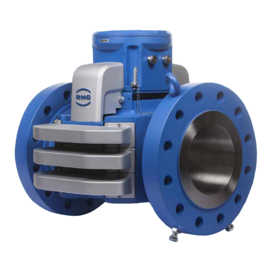
- Page 1 Ultrasonic Flowmeter USM GT400 OPERATING INSTRUCTION Reliable Measurement of Gas Read the instructions before starting work!
- Page 2 +49 6033 897-173 +49 6033 897-130 E-Mail service@rmg.com The Ultrasonic Flowmeter USM GT400 Original Document OPERATING INSTRUCTION 9/4/2018 is the original document. This document may serve as a reference for translations into other languages. Please use in case of any uncertainties the German version as main reference.
-
Page 3: Table Of Contents
Approved measuring range according 13.3 Seals............66 to MID ..........161 Screws ........... 70 13.4 Type plate..........162 Installation possibilities ......71 13.5 Weights and dimensions ..... 163 Flow computer ........75 September, 4 2018 Ultrasonic Flowmeter USM GT400... - Page 4 Pressure devices approval ....177 14.3 Electromagnetic compatibility ....177 14.4 Explosion protection approval....177 14.5 Standards, directives and guidelines ... 178 Index USM GT400 Glossary USM GT400 Attachment Lists of parameters and measured values Ultrasonic Flowmeter USM GT400 September, 4 2018...
-
Page 5: About This Manual
For this reason, you may only use the device as intended and in technically sound condition. If the ultrasonic gas meter is not used for its intended purpose, warranty claims will be void. September, 4 2018 Ultrasonic Flowmeter USM GT400... -
Page 6: Specialized Knowledge Required
• recognize dangers that could be caused by the used flow medium. • training / education by RMG for working with gas measuring instruments. • education / instruction in all country-specific standards and directives to be observed for work that is to be carried out on the device. -
Page 7: Symbols
Validity of the manual This manual describes the Ultrasonic Flowmeter USM GT400. The Ultrasonic Flowmeter USM GT400 device is only a part of a complete on site system. Observe also the instructions of other components of the site system. - Page 8 1 About this manual Ultrasonic Flowmeter USM GT400 September, 4 2018...
-
Page 9: Brief Instructions
Unidirectional operation 10 D (no flow conditioner) 1.5 D to 5 D Unidirectional operation 3 / 5 D (with RMG or stan- 1.5 D to 5 D dardized flow conditioner) Bidirectional operation 10 D (no flow conditioner) 10 D (no flow conditioner) -
Page 10: Electrical Connection
Fig. 2-1: Connection assignment on the terminal strip 10 Connect the computer to the terminals RS 485-0. 11 Allocate the terminal strips according to the applications. Option: connect ERZ 2000 (-NG) to RS 485-1. Ultrasonic Flowmeter USM GT400 September, 4 2018... -
Page 11: Start Up
The marking of the cable (numbers) is (always) identical to the terminal assignment. Earthing Earthing screw M6 Earthing screw M6 Earthing cable Fig. 2-2: Connect to earth - Ultrasonic gas meters DN150 (6") and DN100 (4") September, 4 2018 Ultrasonic Flowmeter USM GT400... -
Page 12: Parameter Setting
Changes to the pre-assembly are more extensive and are therefore not described in this brief instruction. If this should be necessary, you will then find the description: Section 10.1.3, "Calibration and Service Switch" on page 119 Ultrasonic Flowmeter USM GT400 September, 4 2018... -
Page 13: Device Overview
Covers of the transducer lines transducer lines Ultrasonic electronics Lifting eyes Joining flanges Transducer Retaining bolts Fig. 3-1: Main components of the ultrasonic gas meter The ultrasonic gas meter consists of the following main components: September, 4 2018 Ultrasonic Flowmeter USM GT400... - Page 14 The retaining bolts are mounted when delivering the device. The retaining bolts secure the product from tipping over or rolling away. The bolts must be mounted to ensure for a safe installation or de-installation. Ultrasonic Flowmeter USM GT400 September, 4 2018...
-
Page 15: Ultrasonic Electronics
RMGView software. Service and calibration switch (A) The service switch (right switch) is only for RMG service. The ser- vice switch is, e.g., used to install new firmware. The calibration switch (left switch) protects the parameters against unauthorized changes. - Page 16 The calibration switch is open. The value of the parameter can be changed. The calibration switch is closed. The value of the parameter can- not be changed. Forth line Shows the warning, alarm and status messages, e.g., -01 power failure Ultrasonic Flowmeter USM GT400 September, 4 2018...
- Page 17 When holding for a longer time, you can change the lines with quick return. Enter values. Reset button The reset button (A) is for RMG service only. If the reset button is pressed, the ultrasonic electronics is restarted. Switches Calibration switch (A): Activate to change parameters.
- Page 18 Warning Warning message is Warning is active. stored. Reset Reset is running. — Calibration Calibration switch is — open. Service Service switch is — open. Control panel Panel is being — pressed. Ultrasonic Flowmeter USM GT400 September, 4 2018...
-
Page 19: Arrangement Of The Ultrasonic Trans- Ducers
The arrangement of the transducers in the three levels is shown in three section representations. Four transducers are installed per level. The transducers form two paths per level for the measurement. September, 4 2018 Ultrasonic Flowmeter USM GT400... - Page 20 3 Device overview Ultrasonic Flowmeter USM GT400 September, 4 2018...
-
Page 21: Functional Principle - Ultrasonic Flow Measurement
TD1 to transducer TD2 more quickly than the other way around. This is caused physically by vector addition of the flow velocity to the speed of sound, the arrow above the shows the direction of flow. September, 4 2018 Ultrasonic Flowmeter USM GT400... - Page 22 2 d 2 d TD12 TD21 TD12 TD21 Fig. 4-3: Formula, average path velocity Legend Average flow velocity Speed of sound : Path angle to the pipe Path length Ultrasonic Flowmeter USM GT400 September, 4 2018...
- Page 23 Fig. 4-5: Formula, flow velocity Legend = Average flow velocity (m/s) = Weighting factor with regard to the flow profile The summation and the weighting specified result from the math- ematic Gaussian integration procedure. September, 4 2018 Ultrasonic Flowmeter USM GT400...
- Page 24 If the values are within given ranges, then good mea- surement conditions can be assumed. If the values are outside the accuracy of the reading may be affected by disturbed flow conditions. Please contact in this case the RMG service. "Manufacturer" on page I Turbulence Due to the actual flow, in particular the turbulence, there will be ...
-
Page 25: Correction Of The Base Line
Correction of the baseline for the velocity There are several influences (eg. Reynolds number) resulting in a not exactly proportional relation between the measured and ac- cording to the formula 4.5 calculated mean velocity to the exact September, 4 2018 Ultrasonic Flowmeter USM GT400... -
Page 26: Base Line Correction Via Polynomial
v const G – const G – const G – ------------------------------ - ------------------------------ - Fig. 4-14: Formula - Basic correction of the device Legend Deviation of the error curve Ultrasonic Flowmeter USM GT400 September, 4 2018... - Page 27 F and flow Q . The characteristic curve correction K is used for further calculation of the corrected process volume flow. ---------------- Fig. 4-17: Formula, characteristic curve correction September, 4 2018 Ultrasonic Flowmeter USM GT400...
-
Page 28: Diagnostic Function Speed Of Sound
SoS calculation via gas components The second version of SoS calculation uses pressure, tempera- ture and composition of the gas to determine the SoS according to the specifications of the AGA 10 standard (AGA Report No. 10, Ultrasonic Flowmeter USM GT400 September, 4 2018... -
Page 29: Extended Sos Calculation
1 results in the higher temporal resolution for the gas composi- tion, respectively the calorific value. 4.3.3 Extended SoS calculation The third possibility SoS calculation is presented under the name "Extended SoS measurement". This new method is introduced as an additional determination. September, 4 2018 Ultrasonic Flowmeter USM GT400... - Page 30 If correct, the result of the extended measurement is preferred due to its higher accu- racy. Otherwise, the standard method 1 is used; after any change Ultrasonic Flowmeter USM GT400 September, 4 2018...
-
Page 31: Import Of Gas Composition Data
4.4.1 Option 4: Data input on fixed defaults If there are no live data available for the gas analysis, then the gas data can be stored as fixed values in the USM-GT-400. For September, 4 2018 Ultrasonic Flowmeter USM GT400... -
Page 32: Option 4: Data Input On Fixed Defaults For Air
All other possibilities to transmit the volume fractions of the indi- vidual gas components on the USM-GT-400, will use interface 2 of the USM-GT-400. Terminal connections The following figure shows the terminal connections. Ultrasonic Flowmeter USM GT400 September, 4 2018... - Page 33 AGA-10 calculation or default values AX-04 and AX- Fig. 4-23: Pressure and Temperature input The electric connection of pressure (p) and temperature (T) has to be done a terminals 26 to 31; AUX1 = p; AUX2 = T. September, 4 2018 Ultrasonic Flowmeter USM GT400...
-
Page 34: Data Input Via Rmgbus
RMGBus telegram via the RMGBus protocol. Therefore, the coordinate AX-01 “SoS AGA-10 source data“ is set to "Serial port 2" and the serial interface in the mode "RMG- Bus". Additionally the parameters of the interfaces USM-GT-400 and the RMGBus master device have to be aligned to each other. -
Page 35: Import Of Data Via Modbus (Usm-Gt-400 Is Master)
Parameter AX-10 "Modbus Master Target" sets which device the USM-GT-400 is addressing. If the GC9300 is chosen no Modbus register needs to be set at AZ-01 to AZ-54 for status and part of the gas component. September, 4 2018 Ultrasonic Flowmeter USM GT400... - Page 36 24 components adding some (surplus) gas components to other components. Neo-pentane: added to n-pentane (see ISO 12213-2) Propene: added to propane Ethene: added to CO (see ISO 12213-2) Ultrasonic Flowmeter USM GT400 September, 4 2018...
- Page 37 100 mol-% (can only be applied if the sum is > 0 mol-% and < 110 mol-%). Otherwise, Bit 0 in AW-01 "SOS calculation status" will be set and the calculation takes place with 100 mol-% meth- ane instead. Fig. 4-25: Sequence of gas components treatment September, 4 2018 Ultrasonic Flowmeter USM GT400...
- Page 38 21 AGA-10 components Example 1 AGA-10 Component Input AGA-10 unnormalized normalized mol-% mol-% mol-% Methane 35.0 35.0 70.0 Ethane 10.0 Propane Propene iso-Pentane n-Pentane Ethen Hexane+ (5.0) Hexane Nonane 50.0 50.0 100.0 Ultrasonic Flowmeter USM GT400 September, 4 2018...
- Page 39 If there are new gas components latest within three times of the given timeout time, the error status will be reset. Temperature Error The temperature measurement is disturbed. Calculation will be done with the default value. September, 4 2018 Ultrasonic Flowmeter USM GT400...
-
Page 40: Batch Mode
4 signals superimposed. If the F-Batch is active the ring down time should be chosen as short as possible, preferably to 0 ms. The slow batch mode can be activated in coordinate AI-09; it is to be squared for all paths, too. Ultrasonic Flowmeter USM GT400 September, 4 2018... -
Page 41: Safety
.......... 45 Responsibilities of the operator ....... 46 Intended use The Ultrasonic Flowmeter USM GT400 device is used to mea- sure the flow velocity of the gases in a pipeline and calculate the operating flow during running operation. -
Page 42: Layout Of Instructions
This information gives you tips on how to simplify your work. With this screen, you additionally receive further information on the device or the work process. Ultrasonic Flowmeter USM GT400 September, 4 2018... -
Page 43: Qualification Of The Personnel
DIN VDE 0105, IEC 364 or a similar national standards.. • Initial start up must only be carried out by especially trained personal (training by RMG) or by service personal from RMG. • Maintenance and cleaning must only be carried out by the respectively qualified specialist personnel. -
Page 44: Hazards During Transporting
Lift the device only on the intended lifting eyes. • Before lifting, make sure that the load is safely secured. • Never stand under suspended loads. • Observe the weight specifications for the ultrasonic gas meter at hand. Ultrasonic Flowmeter USM GT400 September, 4 2018... -
Page 45: Hazards During Installation
• Use only an Atex or IECEx certified EMC cable screw con- nection in the protection category increased safety with a metric thread (M20x1.5). September, 4 2018 Ultrasonic Flowmeter USM GT400... - Page 46 Before start up, seal all open connections with certified blind plugs according to 94/9/EC. • Replace the blind plugs that have been installed for transpor- tation with certified blind plugs according to 94/9/EC or NEC 500. Ultrasonic Flowmeter USM GT400 September, 4 2018...
-
Page 47: Hazards During Start Up
Cleaning agents / corrosion protection used may be harmful to health. • Always wear protective gloves and eye protection. • Ensure for good ventilation and do not inhale vapors! • Observe the safety data sheet! September, 4 2018 Ultrasonic Flowmeter USM GT400... -
Page 48: Hazards During Maintenance And Repairs
• In doing so, observe the specifications of the system manu- facturer or system operator. Use only genuine spare parts from RMG. • It is forbidden to install spare parts from third-party manufac- turers. It voids all guarantees and claims for guarantee. The explosion protection is no longer ensured. -
Page 49: Hazards During Operation
Operate the device only in a sound and complete state. If you carry out technical changes to the device, safe operation can no longer be guaranteed. • Use the device only in its original state. September, 4 2018 Ultrasonic Flowmeter USM GT400... -
Page 50: Responsibilities Of The Operator
„Qualification of the personnel“ on page 39 • Using suitable measures, ensure that that constructive risks are ruled out when using the device. Inform your personnel about the risks when using the device. Ultrasonic Flowmeter USM GT400 September, 4 2018... -
Page 51: Transport And Storage
Checking the device after storage ......63 Transport The device will be packed to customer-specifics according to the transport requirements. In this chapter you will receive informa- tion on the standard packaging of the device. September, 4 2018 Ultrasonic Flowmeter USM GT400... -
Page 52: Scope Of Supply
The following are included in the scope of supply: Component Quantity Ultrasonic gas meter USM GT400 (including US-Electronic) Extension box In countries where ATEX / IECEx standards apply, connected at the ultrasonic electronic) Special tools to open the US electronic... -
Page 53: Transporting The Device
Options for the outer packaging can be, for example: • sea-proof wooden crate • cardboard packagings 1 Remove the outer packing. September, 4 2018 Ultrasonic Flowmeter USM GT400... - Page 54 6 Transport and storage 2 Recommendation: store the outer packaging for the future or for returning to RMG for service work. Retaining bolts Fig. 6-2: Retaining bolts of the device 3 Make sure that the retaining bolts (A) are screwed in, if necessary.
- Page 55 • Observe the weight specifications for the ultrasonic gas meter at hand. 1 Attach a suitable lifting gear (B) to the lifting eyes (A) of the device. 2 Tension the chain of the lifting gear slightly to secure the device. September, 4 2018 Ultrasonic Flowmeter USM GT400...
- Page 56 5 Pull the Euro pallet from under the device. 6 Recommendation: store the Euro pallet for the future or for returning to RMG for service work. Ultrasonic Flowmeter USM GT400 September, 4 2018...
-
Page 57: Disposal Of Packaging Material
Removing the protective sticker / blind plugs from the flanges The flanges are supplied sealed with a protective sticker or blind plug made of plastic. September, 4 2018 Ultrasonic Flowmeter USM GT400... - Page 58 2 Remove any residual adhesives or other impurities from the sealing surfaces of the flange using a gentle cleaning agent. Remove the blind plugs 1 Pull the blind plugs out of the openings. Ultrasonic Flowmeter USM GT400 September, 4 2018...
-
Page 59: Packing The Device For Transportation
If you no longer have the original packaging material and sealing set, you can order the packaging material and sealing set re- quired from RMG. RMG service would be pleased to consult you as to how the de- vice should be packed. You need the following for standard packaging: •... - Page 60 Recommendation: remove the retaining bolts only if it is absolutely necessary. This is the only way to ensure that the device does not tip over or roll away after being installed. Ultrasonic Flowmeter USM GT400 September, 4 2018...
- Page 61 1 Attach a suitable lifting gear (B) to the lifting eyes (A) of the device. 2 Tension the chain of the lifting gear slightly. 3 Undo the bolted connections from the system so that the device can be lifted out. September, 4 2018 Ultrasonic Flowmeter USM GT400...
- Page 62 5 Carefully place the device on the Euro pallet with the lifting gear. 6 Secure the device using the tensioning straps (B). The tensioning straps must have a tight fit and must secure the device. Ultrasonic Flowmeter USM GT400 September, 4 2018...
- Page 63 ESSO RUST BAN 397, Mobil Oil Tecrex 39. Chapter 11.7, „Cleaning the device“ on page 148 2 Place the corrosion protection mat (A) inside the device. September, 4 2018 Ultrasonic Flowmeter USM GT400...
- Page 64 The following sealing bolts supplied must be used in countries where CSA / FM guidelines apply. If only transport is taking place, you can use 1/2" or 1" screws with appropriate length as an alternative. Ultrasonic Flowmeter USM GT400 September, 4 2018...
- Page 65 2 Stick the protective sticker (A) onto the sealing surface of the flange (B). Sealing the flange with blind plugs 1 Insert the blind plugs into the opening of the flange so that the blind plugs have a tight fit. September, 4 2018 Ultrasonic Flowmeter USM GT400...
-
Page 66: Storage
Danger of poisoning! • Avoid long storage times. • Have the device checked by RMG service if the storage time is lon- ger than one year. For this purpose, send the device to RMG. Ultrasonic Flowmeter USM GT400... -
Page 67: Packing The Device For Storage
Danger of poisoning! • Avoid longer storage times. • Have the device checked by RMG service if the storage time is lon- ger than one year. For this purpose, send the device to RMG. Checking the device for any signs of damage There is a high risk to life and limb if a damaged device is used. - Page 68 6 Transport and storage Ultrasonic Flowmeter USM GT400 September, 4 2018...
-
Page 69: Construction And Planning
Two devices series connected (Face to Face) ..74 Flow computer ........... 75 Connection flanges The devices from RMG are equipped with connection flanges. The joining dimensions of the flanges for the pipelines to be con- nected must correspond to the connection dimensions of the device flanges. -
Page 70: Seals
KD = 15 x bD | k1 = 1.1 x bD (N/mm) Spiral seals: k0 x KD = 50 x bD | k1 = 1.4 x bD (N/mm) Octagonal ring- KD = 480 N/mm joint seal:: Ultrasonic Flowmeter USM GT400 September, 4 2018... -
Page 71: Flat Seal
514 (20.24) 515 (20.28) 547 (21.54) 500 (20) 520 (20.47) 595 (23.43) 618 (24.33) 607 (23.90) 625 (24.61) 628 (24.72) 600 (24) 620 (24.41) 695 (27.36) 735 (28.94) 718 (28.27) 730 (28.74) 745 (29.33) September, 4 2018 Ultrasonic Flowmeter USM GT400... -
Page 72: Grooved Gaskets
123.8 100 (4) 123.8 154.0 150 (6) 177.8 221.7 200 (8) 228.6 266.7 250 (10) 282.6 320.7 300 (12) 339.7 377.8 400 (16) 422.3 466.7 500 (20) 530.2 581.0 600 (24) 631.8 682.6 Ultrasonic Flowmeter USM GT400 September, 4 2018... -
Page 73: Spiral Seals
577.9 518 520.7 520.7 577.9 (20) (19.7) (20.69) (22.75) (20.4) (20.87) (22.60) (20.50) (20.5) (22.75) 628.7 603.3 685.8 618 628.7 628.7 685.8 (24) (23.8) (24.75) (27.00) (24.3) (24.80) (26.54) (24.75) (24.75) (27.00) September, 4 2018 Ultrasonic Flowmeter USM GT400... -
Page 74: Screws
Variant 3 bolts with reduced shank may only be used for devices within the area of PED (Pressure Equipment Directive) application. Notice DN80 Screws are provided by RMG for the USM-GT400 for diameter DN80. Depending on the flange type the following hexagonal bolts are used for DN80: PN16/10 PN40/25... -
Page 75: Installation Possibilities
Measurement Canada (MC), the device must be installed with an inlet and outlet piping. With this installation, the device can be used for calibrated mea- surements and for secondary measurements. Unidirectional operation Temperature sensor Fig. 7-4: Unidirectional operation September, 4 2018 Ultrasonic Flowmeter USM GT400... - Page 76 7 Construction and Planning Flow conditioner Temperature sensor Fig. 7-5: Unidirectional operation - compact installation Ultrasonic Flowmeter USM GT400 September, 4 2018...
- Page 77 Fig. 7-6: Bidirectional operation Flow conditioner Temperature sensor Fig. 7-7: Bidirectional operation - compact installation < DN 300 (12") Flow conditioner Temperature sensor Fig. 7-8: Bidirectional operation - compact installation DN 300 (12") September, 4 2018 Ultrasonic Flowmeter USM GT400...
-
Page 78: Two Devices Series Connected (Face To Face)
Malfunctions from pairing the devices incorrectly If the devices do not match one-another for these installation possibili- ties, incorrect measurements may occur. • Please consult RMG if a Face-to-Face installation is possible with the desired devices and number of devices. Tapered bore Inner diameter Fig. -
Page 79: Flow Computer
ERZ 2000 NG • ERZ 2400 If you want to use the flow computer from RMG specified above, you do not have to carry out any configurations. The flow comput- ers from RMG can directly process the protocol of the ultrasonic gas meter from RMG directly. - Page 80 The cable length must not exceed a length of 500 meters / 1640 feet. More information on the installation of a flow computer can be found here: Operating instructions of the flow computer Ultrasonic Flowmeter USM GT400 September, 4 2018...
-
Page 81: Installation
Connecting the flow computer ........ 92 8.3.5 Connection of external DSfG-Device-F via Modbus ..8.3.6 Interface converter ..........108 8.3.7 Connecting the device to earth ......110 Installing the pressure connection ....112 Outdoor installation ......... 114 September, 4 2018 Ultrasonic Flowmeter USM GT400... -
Page 82: Assembly Work Preparations
If the device is put down without the retaining bolts, it can tip over or roll away. Serious injuries may occur. • Before starting work, make sure that the retaining bolts are screwed Ultrasonic Flowmeter USM GT400 September, 4 2018... - Page 83 4 Pull the blind plugs (C) out of the connection. 5 Screw glandes not required must be replaced by explosion- proof screw connections. Recommendation: store the blind plugs for the future or for returning to RMG for service work. September, 4 2018 Ultrasonic Flowmeter USM GT400...
-
Page 84: Installation Of The Device
Risk of intoxication and explosion! • Make sure that the flat seal does not protrude over the sealing sur- face into the pipeline. Observe the instructions for the dimensions! Chapter 13.5,„Weights and dimensions“ on page 163 Ultrasonic Flowmeter USM GT400 September, 4 2018... -
Page 85: Installation Of The Connection Box
2 Tighten the bolts cross-wise in order to avoid tensioning. Notice In general, only the horizontal installation of the USM GT400 is strongly recommended. Turning the meter by more than 2 flange holes should not be used to avoid the collection of condensate in the sensor pockets. - Page 86 Connecting the connection box This version of the connection box is supplied in countries where the ATEX / IECEx standards apply. The external connecting housing is pre-assembled and connect- ed electrically to the ultrasonic electronics ex-factory. Ultrasonic Flowmeter USM GT400 September, 4 2018...
- Page 87 Observe the following when installing: • The cables must be connected according to the lettering. • Select a maximum cable length of three meters. If you need to use longer cables, please contact RMG services. September, 4 2018 Ultrasonic Flowmeter USM GT400...
-
Page 88: Connecting The Device Electrically
2 x direction detectors for bi-directional operation (I/O1/2) • Interface for RMGView (RS 485 0) • Interface for an RMG flow computer (RS 485 1) • Interface for any flow computer (RS 485 2) • Analog output (4-20 mA) •... - Page 89 4 x 2 x 0.75 mm² Twisted pair cable (TP) are only required in case of multiple cir- cuits in one cable. Otherwise, LIYCY 2 x 0.75 mm² is sufficient for all signal outputs. September, 4 2018 Ultrasonic Flowmeter USM GT400...
- Page 90 The numbers given below at each figure only counts the limited number of cables; all cables are labeled due to the number of the basic upper terminal block. Ultrasonic Flowmeter USM GT400 September, 4 2018...
- Page 91 - ¾" sealing fitting Fig. 8-8: ¾" cable gland with 20 wires, size AWG 18 2 ¾" sealing fitting, connected with 20 wires, size AWG 18 (permitted, max. 20; Killark Type ENY-2TM). September, 4 2018 Ultrasonic Flowmeter USM GT400...
- Page 92 For this version, the ERZ 2000 or ERZ 2000 NG cannot be con- nected via the DZU protocol (RS 485-1). Version 4: Maximum assignment 1/2" and 3/4" sealing fitting Fig. 8-10: ½“ and ¾“ sealing fittings with up to 31 wires of size AWG 18 Ultrasonic Flowmeter USM GT400 September, 4 2018...
-
Page 93: Connecting The Power Supply
8.3.1 Connecting the power supply Power supply Fig. 8-11: Connection assignment on the terminal strip 1 Connect the power supply to the terminals 24 VDC (A). Figure 8-16 on page 94 September, 4 2018 Ultrasonic Flowmeter USM GT400... -
Page 94: Digital Interfaces Of Usm-Gt400
IGM- and sequence for sequence for DZU-protocol, too, data types Long data types Long parameterizable and Float and Float byte sequence for data types Long and Float Ultrasonic Flowmeter USM GT400 September, 4 2018... -
Page 95: Connecting The Computer For Rmgview Usm
Connection assignment on the terminal strip 1 Connect the computer to the terminals RS 485-0 (A). In order to connect, you need an interface converter from USB to RS 485. (please see recommendations in chapter 8.3.4). September, 4 2018 Ultrasonic Flowmeter USM GT400... -
Page 96: Connecting The Flow Computer
(A). 1 Open the cover of the connection box. „Open the connection box (Ex-de)“ on page 83 Connecting the flow computer from RMG Connection via data cable for ERZ 2000 Use the following cable: •... - Page 97 2 (and 2 to 1) freely. 1 Connect the first flow computer to the terminals RS 485-1 (A). 2 Connect the second flow computer to the terminals RS 485-1 (B). September, 4 2018 Ultrasonic Flowmeter USM GT400...
- Page 98 Warning and alarm messages are also available. You also have to connect a direction contact for bi-directional operation. 2 Connect the terminal Warn (A) for warning messages. 3 Connect the terminal Alarm (B) for alarm messages. Ultrasonic Flowmeter USM GT400 September, 4 2018...
-
Page 99: Connection Of External Dsfg-Device-F Via Modbus
Therefore the connection via DSfG-device-F has become the standard in Germany. Since the USM GT400 does not have its own DSfG bus access, its DSfG-instance-F protocol is implemented externally via a flow computer, the ERZ 2000-NG, which has this access. To realize the access the necessary data are transferred between the ... - Page 100 The corresponding settings can be found in the VK Modbus Master USM menu in the ERZ2000-NG. The corresponding register expressions can be found in the VJ register expressions menu. In the USM GT400, the Modbus registers of instance F are listed in column BA. Electrical connection The following figure shows the rear panel of the ERZ2000-NG.
- Page 101 RS 485-2 is provided with terminal 21 (GND), terminal 22 (Data +) and terminal 23 (Data -). Fig. 8-19: Connection of the RS 485-2 (22 +, 23 -) at the USM GT400 September, 4 2018 Ultrasonic Flowmeter USM GT400...
- Page 102 COM6 and 7 slots, which is the first one from the right looking from the display. Fig. 8-20: Configuration of the option card to be used as COM 6 and 7 of the ERZ 2000-NG Ultrasonic Flowmeter USM GT400 September, 4 2018...
- Page 103 GB Flow rate parameter is activated, the further necessary settings are suggested in this menu (light yellow-green background): • GB16 Volume transducer mode -> "DZU" mode • GB51 Device type -> "USM GT400" • GB53 Meter type -> "USZ" (or "USM") September, 4 2018...
- Page 104 8 Installation Fig. 8-22: Selection of DZU in Vol.transd. mode GB16 The proposal must then be "entered", i. e. accepted. Ultrasonic Flowmeter USM GT400 September, 4 2018...
- Page 105 "DSfG: F-instance" must be defined in the menu VJ register expressions by button selection. The corresponding registers for the Modbus communication are thus suggested. Fig. 8-23: Selection of DSfG: F-Instanz in VJ98 September, 4 2018 Ultrasonic Flowmeter USM GT400...
- Page 106 Therefore, the Modbus Master communication for GC1 and GC2 in the coordinates IL50 and IL51 must be realized via the serial interface COM7. It has to be deactivated if no Modbus IP is used. Ultrasonic Flowmeter USM GT400 September, 4 2018...
- Page 107 Operating mode: OFF Configuration VK Modbus according to instance F For communication via DSfG Instance-F, VK Modbus Master USM must be parameterized according to the DSfG Instance-F specification as shown in the following figure. September, 4 2018 Ultrasonic Flowmeter USM GT400...
- Page 108 Configuration oof Mobus Master USM due to Instanz-F The Modbus address in VK52 must be assigned with the address of the USM GT400 are the same. They can be found in J-31. Selection values in VK58 and VK59 are irrelevant because these data types are not included in the instance protocol.
- Page 109 Byte order. It will not be treated here, in case it is required you may have a look into the German manual of the USM GT400. Modbus Registers for Device-F The Modbus registers for device-F can be found in chapter 18 the Appendix with the List of parameters.
- Page 110 - could be taken into account. If one of ten measurements within a measurement cycle for a path is wrong (i.e. 9 valid measurements) the DSP provides 90% valid mea- surements and the path performance is 90%. Ultrasonic Flowmeter USM GT400 September, 4 2018...
- Page 111 Modbus addresses can be seen (see below). Detailed information including hourly averages and deviations of the individual values from the mean value can be found in the September, 4 2018 Ultrasonic Flowmeter USM GT400...
-
Page 112: Interface Converter
Here Phoenix module FL COMSERVER UNI 485-2313452 may be used. Link: https://www.phoenixcontact.com/online/portal/de?uri=pxc-oc- itemdetail:pid=2313452&library=dede&pcck=P&tab=1 Fig. 8-32: Interface converter Ethernet to RS 485 Interface converter from USB to RS 485 (USM-GT- 400) There are 3 recommendations: 1. I-7561 U-G CR at: http://www.icpdas-europe.com Ultrasonic Flowmeter USM GT400 September, 4 2018... - Page 113 Type USB-RS485-WE-5000-BT 730-0164 (5,0 m) s 3. USB-RS485-Converter / part number: 0202047 at: http:// www.ipcas.com Fig. 8-35: Type 0202047s You may find more details of the interface converters and their product information at the given links September, 4 2018 Ultrasonic Flowmeter USM GT400...
-
Page 114: Connecting The Device To Earth
(4") Earthing screw M6 Earthing screw M6 Earthing cable Fig. 8-36: Connect to earth - Ultrasonic gas meters DN150 (6") and DN100 (4") 1 Fasten the customers earthing to the earthing screw (A). Ultrasonic Flowmeter USM GT400 September, 4 2018... - Page 115 The transducers are metallic connected to the meter housing. You do not have to earth the transducer separately. You must en- sure that the conductive connection with the pipeline of the measuring system is established. September, 4 2018 Ultrasonic Flowmeter USM GT400...
-
Page 116: Installing The Pressure Connection
(A and B) or without a shut-off valve (C and D). If the device is or- dered without a shut-off valve, the connection is provided with a union nut (clamping screw connection) or a female thread. Ultrasonic Flowmeter USM GT400 September, 4 2018... - Page 117 DN150 Female thread ¼" Blind plug (screwed) Fig. 8-40: Connection options of the pressure connection with female thread 1 Unscrew the blind plug (B). 2 Seal the connection in the female thread (A). September, 4 2018 Ultrasonic Flowmeter USM GT400...
-
Page 118: Outdoor Installation
US electronic 5. If you expect higher temperatures than 55 ° C, then the USM- GT-400 has to be protected under a large sun-shield (weather protection roof or similar). Ultrasonic Flowmeter USM GT400 September, 4 2018... -
Page 119: Start Up
70% under difficult flow conditions, for example, with high flow rates. If the operating pressure is not reached, a functional check is only possible to a limited extent. In this case, contact RMG services. September, 4 2018 Ultrasonic Flowmeter USM GT400... -
Page 120: Reading Out Speed Of Sound
If one individual path has failed, then there is probably an error in the wiring or with the transducers of this path. Further information can be found at: Chapter 12, „Alarm and warning messages“ on page 151 Ultrasonic Flowmeter USM GT400 September, 4 2018... -
Page 121: Operation
10.3.3 Interface 2 ............132 10.4 Modbus communication in detail ....141 10.4.1 Codes supported ..........141 10.4.2 Data types ............142 10.5 List of the measurement values and parameters ............143 September, 4 2018 Ultrasonic Flowmeter USM GT400... -
Page 122: Measuring Values And Parameters
Under coordinate AG-32 the value for the unit m/s is converted to ft/s. All parameters and measuring values with this variable unit &v: are converted to ft/s. Ultrasonic Flowmeter USM GT400 September, 4 2018... -
Page 123: Calibration And Service Switch
• Two frequency outputs for the actual flow • Two outputs for two flow directions • Alarm and warning contacts Serial protocols are: • DZU • DZU-DIAG • DZU-X • IGM and USE09 • VO • DZU-SLAVE September, 4 2018 Ultrasonic Flowmeter USM GT400... -
Page 124: Interface For Service And Parameterization
3. J-14 mode serial 1 (extended menu: DZU slave) 4. J-23 DZU-1 Address 5. J-25 opt. ser2 mode (extended menu: DZU-Slave) 6. J-37 DZU-2 address Notice • This mode can be used only in areas where the MID is applied. Ultrasonic Flowmeter USM GT400 September, 4 2018... -
Page 125: Calling Up And Changing The Parame- Ters Via The Ultrasonic Electronics
In order to operate the buttons with the magnets (B), the magnet must be placed on the glass in the position with the switching point (A) of the button. September, 4 2018 Ultrasonic Flowmeter USM GT400... -
Page 126: Calling Up The Value Of A Parameter
• Press the button longer: continuously line by line upwards. 1 Press the buttons to select the desired line. The coordinates (column and line) of the parameter are selected. The value of the parameter is shown on the display. Ultrasonic Flowmeter USM GT400 September, 4 2018... -
Page 127: Entering Data
2 Press the button to select a value from the list. Possible value of the list: 0 /…/ 9 / - / + / . / E / _ 3 Press the button to confirm the value. The value is stored. September, 4 2018 Ultrasonic Flowmeter USM GT400... - Page 128 2 Press the button to select a value from the list. Possible value of the list: 0 /…/ 9 / - / + / . / _ / A /…/ Z 3 Press the button to confirm the value. The value is stored. Ultrasonic Flowmeter USM GT400 September, 4 2018...
- Page 129 1 Press the button until the next value is marked in the display. 2 Press the button to select a value from the list. 3 Press the button to confirm the value. The value is stored. September, 4 2018 Ultrasonic Flowmeter USM GT400...
-
Page 130: Changing The Parameters Of Protection E And S
If the task is carried out by RMG service, the device does not have to be calibrated by a testing institute. The device is provided with a new official seal by RMG service. - Page 131 Opening the cover 2 Unscrew threaded pin (A) out of the housing. 3 Insert the special tools into the boreholes. 4 Release the cover with the special key. Cover Fig. 10-3: Open the cover September, 4 2018 Ultrasonic Flowmeter USM GT400...
- Page 132 Screw down the cover 1 Each time you open the ultrasonic electronic you have to expect that the O-ring is damaged. Therefore, this damaged O-ring has to be replaced with a new one in general. (RMG Ultrasonic Flowmeter USM GT400 September, 4...
- Page 133 Entering the code word of the ultrasonic electronics If you do not have the password for the ultrasonic electronics, request the code word from RMG Service. 1 Enter the code word for the ultrasonic electronics under coor- dinate AG-4.
- Page 134 6 Activate the button with the magnet in order to confirm the desired value. When the parameter is changed, you have to move the cali- bration switch back to the closed position. Calibration switch Fig. 10-7: Close the calibration switch Ultrasonic Flowmeter USM GT400 September, 4 2018...
-
Page 135: Parameterize The Usm Interface
2104 mode J-07 Modbus-0 address 2105 J-08 Modbus 0 reg.offset 2106 J-09 Modbus 0 gap time 2118 J-10 Pressure applica- 2116 tion J-11 Lpt interval 2117 J-12 DZU-0 address 2283 J-13 Serial-0 status September, 4 2018 Ultrasonic Flowmeter USM GT400... -
Page 136: Interface 1
J-28 Opt. Ser2 parity NONE 2115 J-29 Modbus 2 protocol 2178 J-30 Modbus 2 HW RS485 2179 mode J-31 Modbus-2 address 2180 J-32 Modbus 2 Reg.off- 2181 J-33 Modbus 2 Gap time 2182 Ultrasonic Flowmeter USM GT400 September, 4 2018... - Page 137 To activate the Modbus Master, the mode must be set to Modbus master. Fig. 10-9: Activation as Modbus master Coordinates AW-08 and AW-09 indicate the time since of the last AGA10 calculation respectively the time of last update of the gas components. September, 4 2018 Ultrasonic Flowmeter USM GT400...
- Page 138 Formula N-Pentane USM_Ob AZ-17 Formula Hexane+ USM_Ob AZ-18 Formula Hexane+ USM_Ob AZ-19 Formula Oxygen F8280 USM_Ob AZ-20 Formula Oxygen USM_Ob AZ-21 Formula Helium F8282 USM_Ob AZ-22 Formula Helium USM_Ob AZ-23 Formula Hydrogene F8284 Ultrasonic Flowmeter USM GT400 September, 4 2018...
- Page 139 Formula Ethene USM_Ob AZ-48 Formula Ethene USM_Ob AZ-49 Formula Propene USM_Ob AZ-50 Formula Propene USM_Ob AZ-51 Formula Status u1038==0 USM_Ob AZ-52 Formula Status USM_Ob AZ-53 Formula Status USM_Ob AZ-54 Formula Status USM_Ob AZ-55 MB_Pause September, 4 2018 Ultrasonic Flowmeter USM GT400...
- Page 140 “Treatment of the gas data” on page 32 It might be possible that there is no input field in the USM-GT-400 for a measured gas component from the PGC, for example, Neo- Ultrasonic Flowmeter USM GT400 September, 4 2018...
- Page 141 Constants It might be possible that components required from the USM-GT- 400 are not given from the PGC, for example water and hydrogen sulfide. These can be set to 0: September, 4 2018 Ultrasonic Flowmeter USM GT400...
- Page 142 The number of pending alarms shows the data type of an unsigned integer (unsigned short int). The prefix is a small u. The register address is 10, therefore, the value u10 should be requested. Ultrasonic Flowmeter USM GT400 September, 4 2018...
- Page 143 20 characters. If this is insufficient for the formulation of a more complex expression, there are a total of four coordinates for the status. AX-51 Formula Status (lowest significance) AX-52 Formula Status (low significance) September, 4 2018 Ultrasonic Flowmeter USM GT400...
- Page 144 It increases with the value of the byte. The se- quence is read from left to right. Fig. 10-16: Significance of the coordinates AY-46 telegram counter: Here all correct PGC answers are counted. Ultrasonic Flowmeter USM GT400 September, 4 2018...
-
Page 145: Modbus Communication In Detail
Modbus communication in detail 10.4.1 Codes supported The ultrasonic electronics supports the following codes: Function codes Code Description 03 Hex Read Holding Registers 06 Hex Preset Single Register 10 Hex Preset Multiple Registers 08 Hex Diagnostic September, 4 2018 Ultrasonic Flowmeter USM GT400... -
Page 146: Data Types
Start Char Slave Address Function Starting Address Hi Starting Address Lo Register = 4002 (0FA2) No. of Points Hi No. of Points Lo Amount = 0001 (0001) LRC / CRC carriage return line feed Ultrasonic Flowmeter USM GT400 September, 4 2018... -
Page 147: List Of The Measurement Values And Parameters
Data Lo (Reg 2000) Value = A801 carriage return line feed Value in ASCII Value in HEX 10.5 List of the measurement values and parameters The lists for parameter and measured values are in appendix 18. September, 4 2018 Ultrasonic Flowmeter USM GT400... - Page 148 10 Operation Ultrasonic Flowmeter USM GT400 September, 4 2018...
-
Page 149: Maintenance
11.4 Changing the battery ........147 11.5 Changing the transducer ........ 147 11.6 Changing the ultrasonic electronics ....148 11.7 Cleaning the device ......... 148 11.8 Check the official seal ........149 11.9 Decommissioning and disposal ..... 149 September, 4 2018 Ultrasonic Flowmeter USM GT400... -
Page 150: Maintenance Schedule
For safe operation, the device must be sent back to RMG every 5 to 10 years to check for leaks. In the course of a recalibration from RMG, the device will also be checked for leaks at the same time. -
Page 151: Checking The Device For Any Signs Of Damage
• Change the transducer only if you have obtained a training from RMG for this activity. • Observe the separate service instructions for changing the trans- ducer. The special tool from RMG must be used for changing the transducers. September, 4 2018... -
Page 152: Changing The Ultrasonic Electronics
• Have a device that is contaminated on the inside only cleaned by RMG service or by personnel that have been especially trained by RMG. Damage to the device from incorrect cleaning agent... -
Page 153: Check The Official Seal
The device mainly comprises materials that can be disposed of as old metal. In the following we shall specify the components that may not be disposed of as old metal. September, 4 2018 Ultrasonic Flowmeter USM GT400... - Page 154 The transducer comprises titanium, plastic and heavy metals (e.g., lead in piezo crystal). The transducers must be disposed of according to the applicable national and local guidelines. In order to remove the transducers, RMG service shall inform you of the procedure. „Manufacturer“ on page I...
-
Page 155: Alarm And Warning Messages
In this chapter, you will find out which information, alarm and warning messages can be displayed. In this chapter, you will also find out how to eliminate problems with the RMG components. Active warning messages are displayed with a + in front of the message number. - Page 156 No valid measurement, all measuring paths have failed. Timeout ADC fault temperature input temperature ADC pressure ADC fault pressure input I1 Out min/ Power outlet outside the min. / max. limits Temp.min/ Temperature outside the min. / max. limits Ultrasonic Flowmeter USM GT400 September, 4 2018...
- Page 157 P8 AGC limit Amplification factor for path 8 outside the permissible limits (spare) QVb min. limit Operating volume flow below Qmin QVb max. limit Operating volume flow above Qmax Wrong param. Parameter entered is invalid September, 4 2018 Ultrasonic Flowmeter USM GT400...
-
Page 158: Warning Messages
Speed of sound from path 7 outside the min./max. limits (spare) P8 c min/max Speed of sound from path 8 outside the min./max. limits (spare) p1.1 amplitude Amplitude of the signal from sensor 1.1 too small Ultrasonic Flowmeter USM GT400 September, 4 2018... - Page 159 Deviation from the speed of sound in path 8 from the average speed of sound too large (spare) p1 AGC delta Deviation from the amplification factor in path 1 from the average amplification factor too large September, 4 2018 Ultrasonic Flowmeter USM GT400...
- Page 160 Deviation from the amplification factor in path 7 from the average amplification factor too large (spare) p8 AGC delta Deviation from the amplification factor in path 8 from the average amplification factor too large (spare) Ultrasonic Flowmeter USM GT400 September, 4 2018...
-
Page 161: Notes
Status of the SoS calculation 12.4 Troubleshooting If you cannot find a solution to your problem with the RMG com- ponent in the table below, then please contact the RMG service. „Manufacturer“ on page I If problems cannot be eliminated, please contact RMG service. - Page 162 Thus, one has the option to already identify conspicu- 170-175 ous paths when the limit values relevant for the calibration have not been violated for the validity of the measurement yet. Possible causes are identical with those described in 100 -125. Ultrasonic Flowmeter USM GT400 September, 4 2018...
-
Page 163: Technical Specifications
13.6 Inner diameter of connecting spool pieces ... 167 13.7 Official seal diagram ........168 13.7.1 Type plate ............. 168 13.7.2 Ultrasonic electronics ........... 169 13.7.3 Ultrasonic gas meter ..........171 13.8 Transducer types ..........173 September, 4 2018 Ultrasonic Flowmeter USM GT400... -
Page 164: Performance Data
The components of the gases must be within the concentration limits for test gases according to EN 437:2009 or similar national standards. The national standards of other countries demand similar gas type specifications. Ultrasonic Flowmeter USM GT400 September, 4 2018... -
Page 165: Approved Measuring Range According
USM (flow, pressure and temperature range) and must be free of corrosive and aggressive components, liquids and solids. In case of deviating conditions a suitable operation has to be agreed with the RMG service. 13.3 Approved measuring range according to MID Nominal diameter Measuring range... -
Page 166: Type Plate
Type plate Type plate Fig. 13-1: Position of type plate The following details can be found on the type plate: 13.4.1 Type plate ATEX / IECEx Fig. 13-2: Type plate ATEX / IECEx Ultrasonic Flowmeter USM GT400 September, 4 2018... -
Page 167: Weights And Dimensions
NEC and ATEX /IECEx. ANSI pressure stages: The flange connecting dimensions com- ply with the standard ASME B 16.5. DIN pressure stages: The flange connecting dimensions com- ply with the standard DIN EN 1092. September, 4 2018 Ultrasonic Flowmeter USM GT400... -
Page 168: Atex / Iecex
The version NEC and version ATEX / IECEx have identical di- mensions. The table of the versions can be found on the following location: „Dimensions – Version NEC and ATEX / IECEx“ on page 167 Ultrasonic Flowmeter USM GT400 September, 4 2018... - Page 169 13 Technical specifications 13.5.2 ATEX / IECEx Fig. 13-5: ATEX / IECEx September, 4 2018 Ultrasonic Flowmeter USM GT400...
- Page 170 13 Technical specifications Fig. 13-6: DN80 Due to the different sizes of the individual components, the de- vice in DN80 is shown separately. Ultrasonic Flowmeter USM GT400 September, 4 2018...
-
Page 171: Inner Diameter Of Connecting Spool Pieces
The given values are for pressure level ANSI 600, respectively ANSI900 (specified). Maximum diameter at the flange, depending on tapering. Approximate dimension. Approximate values. Weights can vary due to casting tolerances. An angle of 7° is used for tapering. September, 4 2018 Ultrasonic Flowmeter USM GT400... -
Page 172: Inner Diameter Of Connecting
13 Technical specifications 13.6 Inner diameter of connecting spool pieces Connection diameter at tapering of the USM GT400 (= inner diameter for inlet and outlet spool pieces) Maximum deviation from meter to piping: +/- 1% acc. MID / AGA 9 For calibrated spool pieces belonging to the measuring instru- ment, the deviation may be up to +/- 3%. -
Page 173: Official Seal Diagram
In this chapter you will receive information at which location the official seals are attached to the device. The device must not be used for a calibrated operation if the offi- cial seal is broken. September, 4 2018 Ultrasonic Flowmeter USM GT400... -
Page 174: Type Plate
13 Technical specifications 13.7.1 Type plate Official seal Fig. 13-7: Position of the official seal on the type plate Ultrasonic Flowmeter USM GT400 September, 4 2018... -
Page 175: Ultrasonic Electronics
13 Technical specifications 13.7.2 Ultrasonic electronics Official seal diagram according to ATEX / IECEx Fig. 13-8: Representation of the device with DN 150 (6") September, 4 2018 Ultrasonic Flowmeter USM GT400... - Page 176 13 Technical specifications Official seal diagram according to NEC Fig. 13-9: Representation of the device with DN 150 (6") Ultrasonic Flowmeter USM GT400 September, 4 2018...
-
Page 177: Ultrasonic Gas Meter
13 Technical specifications 13.7.3 Ultrasonic gas meter Devices DN 100 (4") and DN 150 (6 ") Fig. 13-10: Representation of the device with DN 150 (6") September, 4 2018 Ultrasonic Flowmeter USM GT400... - Page 178 13 Technical specifications Devices DN 200 (8 ") and larger Fig. 13-11: Representation of the device with DN 200 (8") Ultrasonic Flowmeter USM GT400 September, 4 2018...
-
Page 179: Transducer Types
+80 °C (14.5 to 2175.57) (55 to 131 °F) (176 °F) 1-300 TNG 20-SHP -40 to +55 °C up to +80 °C (14.5 to 4351.13) (55 to 131 °F) (176 °F) September, 4 2018 Ultrasonic Flowmeter USM GT400... - Page 180 13 Technical specifications Ultrasonic Flowmeter USM GT400 September, 4 2018...
-
Page 181: Usm Gt400 Approval
14 USM GT400 Approval USM GT400 Approval In this section, you will receive information in which fields of ap- plication the device is approved. The standards, guidelines and regulations are also listed which are applied for the development and manufacturing. -
Page 182: Standards, Directives And Guidelines
14 USM GT400 Approval 14.5 Standards, directives and guidelines We, RMG Messtechnik GmbH, herewith declare that due to its design and construction in the version brought onto the market the devices described in this operating instruction conforms to the relevant fundamental health and safety requirements of the applicable EC Directive. - Page 183 14 USM GT400 Approval USA Directives ASME B31.3 Pressure safety Ed. 2012 AGA report no. 9 Measurement of Gas by Multipath Ultrasonic Meters. AGA report no. 10 Speed of Sound in Natural Gas and Other Related Hydrocarbon Gases. Canada-Guideline PS-G-06...
- Page 184 14 USM GT400 Approval USM GT400 September, 4 2018...
-
Page 185: Index
Connect to earth Check Connecting Damage Damage Official seal Decommissioning Tightness Disposal Euro pallet Clamping screw connection Inlet piping Cleaning Installation Device Main components Risks Maintenance Safety instructions Measuring values Connecting flanges Official seal September, 4 2018 Ultrasonic Flowmeter USM GT400... - Page 186 Protective sticker Connection box Flanges Connection box ATEX ANSI Connection box NEC 500 Dimensions Connection boxIECEx Protective sticker Face to Face Flow Flow computer Flow computer Piping Cable length Possibilities Connection example Pressure port Ultrasonic Flowmeter USM GT400 September, 4 2018...
- Page 187 Units (variable) Change Messages Column Alarm message Input protection Status Line Warning signal Tables Meter factor Units (variable) Meter parameter Path Change Path angle to the pipe Column Path length Input protection Performance data September, 4 2018 Ultrasonic Flowmeter USM GT400...
- Page 188 Gaskomp. Mod- RMGBus Installation Messages Maintenance Temperature sensor Operation Temperature stratification Operation in potentially explosive envi- Tension straps ronment Transport Repairs Terminal assignment Start Up Connection box Transport Maximum assignment RMGViewUSM RMGViewUSM Terminal assignment Tightness Ultrasonic Flowmeter USM GT400 September, 4 2018...
- Page 189 NEC (CSA / FM) ATEX Weighting factor IECEx Types Connection box Data Nuts Pressure port Screws Seals Transducer Ultrasonic electronics Battery Buttons Changing Close Display Disposal Enclosure Lead seal Light emitting diodes Opening September, 4 2018 Ultrasonic Flowmeter USM GT400...
- Page 190 15 Index Ultrasonic Flowmeter USM GT400 September, 4 2018...
-
Page 191: Usm Gt400 Glossary
16 USM GT400 Glossary USM GT400 Glossary Transducer In this chapter you will be given information on terminology. The transducer or sensor is built into the device. The transducer sends the opposing transducer an Ultrasonic gas meter (USM) ultrasonic signal. Using the time measured for the ultrasonic signal to travel the distance between the The gas flows through the ultrasonic gas meter. -
Page 192: 16 Usm Gt400 Glossary
16 USM GT400 Glossary USM GT400 September, 4 2018... -
Page 193: Usm Gt400 Attachment
17 USM GT400 Attachment USM GT400 Attachment You will find the declaration of conformity and approvals of the device in this section. September, 4 2018 Ultrasonic Flowmeter USM GT400... -
Page 194: 17 Usm Gt400 Attachment
17 USM GT400 Attachment Ultrasonic Flowmeter USM GT400 September, 4 2018... -
Page 195: 17 Usm Gt400 Attachment
17 USM GT400 Attachment September, 4 2018 Ultrasonic Flowmeter USM GT400... -
Page 196: 17 Usm Gt400 Attachment
17 USM GT400 Attachment Ultrasonic Flowmeter USM GT400 September, 4 2018... -
Page 197: 17 Usm Gt400 Attachment
17 USM GT400 Attachment September, 4 2018 Ultrasonic Flowmeter USM GT400... -
Page 198: 17 Usm Gt400 Attachment
17 USM GT400 Attachment Ultrasonic Flowmeter USM GT400 September, 4 2018... -
Page 199: 17 Usm Gt400 Attachment
17 USM GT400 Attachment September, 4 2018 Ultrasonic Flowmeter USM GT400... -
Page 200: 17 Usm Gt400 Attachment
17 USM GT400 Attachment Ultrasonic Flowmeter USM GT400 September, 4 2018... -
Page 201: 17 Usm Gt400 Attachment
17 USM GT400 Attachment September, 4 2018 Ultrasonic Flowmeter USM GT400... -
Page 202: 17 Usm Gt400 Attachment
17 USM GT400 Attachment Ultrasonic Flowmeter USM GT400 September, 4 2018... -
Page 203: 17 Usm Gt400 Attachment
17 USM GT400 Attachment September, 4 2018 Ultrasonic Flowmeter USM GT400... -
Page 204: 17 Usm Gt400 Attachment
17 USM GT400 Attachment Ultrasonic Flowmeter USM GT400 September, 4 2018... -
Page 205: 17 Usm Gt400 Attachment
17 USM GT400 Attachment September, 4 2018 Ultrasonic Flowmeter USM GT400... -
Page 206: 17 Usm Gt400 Attachment
17 USM GT400 Attachment Ultrasonic Flowmeter USM GT400 September, 4 2018... -
Page 207: 17 Usm Gt400 Attachment
17 USM GT400 Attachment September, 4 2018 Ultrasonic Flowmeter USM GT400... -
Page 208: 17 Usm Gt400 Attachment
17 USM GT400 Attachment Ultrasonic Flowmeter USM GT400 September, 4 2018... -
Page 209: 17 Usm Gt400 Attachment
17 USM GT400 Attachment September, 4 2018 Ultrasonic Flowmeter USM GT400... -
Page 210: 17 Usm Gt400 Attachment
17 USM GT400 Attachment Ultrasonic Flowmeter USM GT400 September, 4 2018... -
Page 211: Lists Of Parameters And Measured Values
21.Path 2 signal analysis 22.Path 3 signal analysis 23.Path 4 signal analysis 24.Path 5 signal analysis 25.Path 6 signal analysis 26.Path 7 signal analysis 27.Path 8 signal analysis 28.USE09 measuring values 29.USE09 diagnosis 30.Times September, 4 2018 Ultraschallgaszähler USM GT400... -
Page 212: 18 Lists Of Parameters And Measured
39.Path 3 Parameter 40.Path 4 Parameter 41.Path 5 Parameter 42.Path 6 Parameter 43.Path 7 Parameter 44.Path 8 Parameter 45.Service 46.Log memory 47.User info 48.Remote control 49.AGA-10 values 50.AGA-10 Configuration 51.Gas comp. RMGBus 52.Gas comp. Modbus Ultraschallgaszähler USM GT400 September, 4 2018... - Page 213 Appendix 1 of 104...
- Page 214 Appendix 2 of 104...
- Page 215 Appendix 3 of 104...
- Page 216 Appendix 4 of 104...
- Page 217 Appendix 5 of 104...
- Page 218 Appendix 6 of 104...
- Page 219 Appendix 7 of 104...
- Page 220 Appendix 8 of 104...
- Page 221 Appendix 9 of 104...
- Page 222 Appendix 10 of 104...
- Page 223 Appendix 11 of 104...
- Page 224 Appendix 12 of 104...
- Page 225 Appendix 13 of 104...
- Page 226 Appendix 14 of 104...
- Page 227 Appendix 15 of 104...
- Page 228 Appendix 16 of 104...
- Page 229 Appendix 17 of 104...
- Page 230 Appendix 18 of 104...
- Page 231 Appendix 19 of 104...
- Page 232 Appendix 20 of 104...
- Page 233 Appendix 21 of 104...
- Page 234 Appendix 22 of 104...
- Page 235 Appendix 23 of 104...
- Page 236 Appendix 24 of 104...
- Page 237 Appendix 25 of 104...
- Page 238 Appendix 26 of 104...
- Page 239 Appendix 27 of 104...
- Page 240 Appendix 28 of 104...
- Page 241 Appendix 29 of 104...
- Page 242 Appendix 30 of 104...
- Page 243 Appendix 31 of 104...
- Page 244 Appendix 32 of 104...
- Page 245 Appendix 33 of 104...
- Page 246 Appendix 34 of 104...
- Page 247 Appendix 35 of 104...
- Page 248 Appendix 36 of 104...
- Page 249 Appendix 37 of 104...
- Page 250 Appendix 38 of 104...
- Page 251 Appendix 39 of 104...
- Page 252 Appendix 40 of 104...
- Page 253 Appendix 41 of 104...
- Page 254 Appendix 42 of 104...
- Page 255 Appendix 43 of 104...
- Page 256 Appendix 44 of 104...
- Page 257 Appendix 45 of 104...
- Page 258 Appendix 46 of 104...
- Page 259 Appendix 47 of 104...
- Page 260 Appendix 48 of 104...
- Page 261 Appendix 49 of 104...
- Page 262 Appendix 50 of 104...
- Page 263 Appendix 51 of 104...
- Page 264 Appendix 52 of 104...
- Page 265 Appendix 53 of 104...
- Page 266 Appendix 54 of 104...
- Page 267 Appendix 55 of 104...
- Page 268 Appendix 56 of 104...
- Page 269 Appendix 57 of 104...
- Page 270 Appendix 58 of 104...
- Page 271 Appendix 59 of 104...
- Page 272 Appendix 60 of 104...
- Page 273 Appendix 61 of 104...
- Page 274 Appendix 62 of 104...
- Page 275 Appendix 63 of 104...
- Page 276 Appendix 64 of 104...
- Page 277 Appendix 65 of 104...
- Page 278 Appendix 66 of 104...
- Page 279 Appendix 67 of 104...
- Page 280 Appendix 68 of 104...
- Page 281 Appendix 69 of 104...
- Page 282 Appendix 70 of 104...
- Page 283 Appendix 71 of 104...
- Page 284 Appendix 72 of 104...
- Page 285 Appendix 73 of 104...
- Page 286 Appendix 74 of 104...
- Page 287 Appendix 75 of 104...
- Page 288 Appendix 76 of 104...
- Page 289 Appendix 77 of 104...
- Page 290 Appendix 78 of 104...
- Page 291 Appendix 79 of 104...
- Page 292 Appendix 80 of 104...
- Page 293 Appendix 81 of 104...
- Page 294 Appendix 82 of 104...
- Page 295 Appendix 83 of 104...
- Page 296 Appendix 84 of 104...
- Page 297 Appendix 85 of 104...
- Page 298 Appendix 86 of 104...
- Page 299 Appendix 87 of 104...
- Page 300 Appendix 88 of 104...
- Page 301 Appendix 89 of 104...
- Page 302 Appendix 90 of 104...
- Page 303 Appendix 91 of 104...
- Page 304 Appendix 92 of 104...
- Page 305 Appendix 93 of 104...
- Page 306 Appendix 94 of 104...
- Page 307 Appendix 95 of 104...
- Page 308 Appendix 96 of 104...
- Page 309 Appendix 97 of 104...
- Page 310 Appendix 98 of 104...
- Page 311 Appendix 99 of 104...
- Page 312 Appendix 100 of 104...
- Page 313 Appendix 101 of 104...
- Page 314 Appendix 102 of 104...
- Page 315 Appendix 103 of 104...
- Page 316 Appendix 104 of 104...
- Page 317 Subject to technical modification. For further information please visit our website: www.rmg.com or contact your local sales support office to learn more about the RMG products. RMG Messtechnik GmbH Otto-Hahn-Strasse 5 35510 Butzbach, Deutschland Phone: +49 6033 897-0 Fax: +49 6033 897-130 E-Mail: service@rmg.com...
Need help?
Do you have a question about the USM GT400 and is the answer not in the manual?
Questions and answers