
Related Manuals for RMG ERZ2000-NG


Summary of Contents for RMG ERZ2000-NG
- Page 1 ERZ2000-NG ERZ2000 ERZ2000-NG Flow Computer Series Flow Computer Series Flow Computer Series OPERATING MANUAL Reliable Measurement of Gas Issued: 2019, May 13th Version: Firmware version:...
- Page 2 Translation of the original The manual ERZ2000NG_manual_de_07 of 2019, document May 13th for the flow computer ERZ2000-NG is the original document. This document is a template for translations in other languages. Note Unfortunately, paper is not updated automatically, whereas technical development continuously ad- vances.
-
Page 3: Table Of Contents
Table of contents TABLE OF CONTENTS 1 ABOUT THIS MANUAL ..... 1 Structure of the manual ................1 Purpose of the manual ................2 1.2.1 Abbreviations ......................2 1.2.2 Symbols ......................... 4 1.2.3 Structure of notices....................4 1.2.4 Working with the device ..................5 1.2.5 Risk assessment and minimization ............... - Page 4 Table of contents 2.5.8 Trend ........................86 2.5.9 Maximum load ..................... 87 Time system ....................89 2.6.1 KA Times and time settings ................. 89 2.6.2 KB Time contact signal to external devices ............92 2.6.3 KC external time signal ..................93 2.6.4 KD Plausibility ......................
- Page 5 Table of contents 4.5.5 IF DSfG master....................167 5 TRANSMITTERS ......170 Measurements ..................171 Pressure transducer ................173 Temperature transducer ................. 180 5.3.1 AL internal temperature of the device ..............181 Special measurements ................182 6 FLOW METERS ......183 General settings ..................
- Page 6 Table of contents 6.4.3 Electrical connection ..................227 6.4.4 USM GT400 connection area ................227 6.4.5 Configuration for COM6 and COM7 ..............228 6.4.6 Volume transmitter operating mode ..............233 6.4.7 Protocol type in menu VJ Register plots ............234 6.4.8 COM6 interface configuration ................
- Page 7 7.6.4 IL Modbus Master GC1 ..................304 7.6.5 IM Modbus Master GC2 ..................307 7.6.6 IH Imported gas quality via RMG bus ..............308 7.6.7 IP Modbus EGO Erdgas Ostschweiz ..............313 8 OVERVIEW: COORDINATES ..315 8.1.1 LS Hourly quantities ..................315 Documentation ..................
- Page 8 Table of contents 9 FAULTS ......... 333 Fault settings ................... 333 9.1.1 JA Fault messages .................... 333 9.1.2 JB Message register ..................335 9.1.3 CJ GIA-Bit table ....................336 9.1.4 JD Debugging ....................337 9.1.5 ON Extra messages ..................338 Error table ....................
- Page 9 Table of contents Optional Ex input board ................393 Instructions for the installer ................393 Various circuit diagrams for outputs ............. 395 Vo digital totalizer ..................396 Examples for use of the revision switch ..........398 Appendix for bus systems ..............401 DSfG bus ......................
-
Page 11: About This Manual
For this reason, the fourth part also includes the complete seal diagram. Signed data that the ERZ2000-NG can be sent has been included as a final sub- section. -
Page 12: Purpose Of The Manual
2. The manual contains numerous cross-references which can also be used to skip to these chapters. 3. All menu items of the ERZ2000-NG are listed in the last chapter of the annex; the cross-references there also make it possible to skip to the corresponding passages. - Page 13 1 About this manual DVGW Deutsche Verein des Gas- und Wasserfaches German Gas and Water Association MessEG Measuring and calibration law Law on placing and providing measuring instruments on the market, their use and calibration; valid since 1.1.2015 MessEV Measuring and calibration regulations Regulation on placing and providing measuring instru- ments on the market;...
-
Page 14: Symbols
1 About this manual 1.2.2 Symbols The following symbols are used: 1, 2, … Identifies steps for work tasks 1.2.3 Structure of notices The following notices are used: Danger This warning notice informs you of imminently threatening dangers that can arise due to misuse/operator error. -
Page 15: Working With The Device
Caution All notices in the manual must be observed. Use of the flow computer ERZ2000-NG is only permitted in accordance with the specifications in the operating manual. RMG assumes no liability for damages arising due to disregard of the operat- ing manual. - Page 16 The technical specifications must be observed and followed for safe operation (chapter 3 Electrical connections). Performance limits must not be exceeded. The flow computer ERZ2000-NG must only be used in the scope of the in- tended use (chapter1.5 Areas of application) The flow computer ERZ2000-NG complies with current standards and regula- tions.
- Page 17 The flow computer ERZ2000-NG is not approved or designed for use in explosion- prone areas. Installation must only take place in safe rooms. The ERZ2000-NG is intended for installation in a control cabinet in an electronics room.
- Page 18 / education in accordance with DIN VDE 0105, IEC 364 or comparable standards. Caution In general, the replacement of a flow computer ERZ2000-NG must only be car- ried out by RMG Service. 1.2.4.3 Dangers during maintenance and repair...
-
Page 19: Risk Assessment And Minimization
1 About this manual Danger The flow computer ERZ2000-NG must only be used as intended! (chapter 1.5 Areas of application). Avoid using the flow computer ERZ2000-NG as a potential climbing aid or as a potential grip! 1.2.4.4 Qualification of personnel... -
Page 20: Applicability Of The Manual
1 About this manual Danger The wiring from and installation of the flow computer ERZ2000-NG in ex- plosion-prone areas must only be carried out by trained personnel in ac- cordance with EN60079-14 and in observance of national regulations. Qualified persons must satisfy the definitions in accordance with DIN EN 0105 or IEC 364 or directly comparable standards. -
Page 21: Transport
1 About this manual 1.2.6.2 Dangers of operation in Ex areas The flow computer ERZ2000-NG is not intended for use in explosion-prone areas. Danger The flow computer ERZ2000-NG must be used exclusively in fault-free and complete, original condition. If you make technical changes to the device, safe operation can no longer be guaranteed. -
Page 22: Disposal Of Packaging Material
For this purpose, send the device to RMG. Note Even if the ERZ2000-NG is stored for a short time only, it is important to ensure a clean and dry environment! Danger Life-threatening danger due to damages occurring during storage. -
Page 23: Function
The resulting billing variables can be represented in a graph and checked via alarm output, etc. The ERZ2000-NG cor- responds to the standards, directives and specifications listed in chapter 1.5 Areas of application. -
Page 24: Overview
1 About this manual 1.4 Overview The ERZ2000-NG, therefore, is an advancement of the ERZ2000 as a half 19" slide- in module (half 19" width). The ERZ2000-NG system has a configuration consisting of 2 function groups with a clear separation between the functions of measurement value determination, quantity conversion, registration and basic tasks. -
Page 25: Areas Of Application
Other equations can also be used (see chapter: 7 Parameter of the gas) The device concept is provided for extension and integration of all individual devices of older series from RMG Messtechnik GmbH as a universal system. Manual ERZ 2000-NG · EN07 · 2019, May 13th... -
Page 26: Device Type Adjustment
Said authority will apply the necessary seals and blockades after the modification. Designations and device variants of the ERZ2000-NG system family Device type switchover Normally, a special factory setting is used for custody transfer applications. The de- vice cannot be used for custody transfer without this special setting. -
Page 27: Use In Gas Measurement Technology
1.5.2 Use in gas measurement technology The ERZ2000-NG is not intended for use in explosion-prone areas. However, it can operate sensors and other devices in explosion-prone areas. Only operate the ERZ2000-NG in fault-free and complete condition. - Page 28 Note The ERZ2000-NG system is approved in different variants for custody-transfer application for gas measurement technology in Germany and other countries. The following EU type examination certificates are available for Germany (see...
-
Page 29: Seal Diagram For Devices With Mid Approval
1 About this manual with Additional Function Energy Conversion Device acc. to EN 12405-2 (Certificate no. DE-13-MI002-PTB003 4th revision) *) *) The function of the calorific value conversion in the ERZ2104 (calculation of energy and energy totalizers in each totalizer unit) is an integrated function in the sense of MID, but is not subject to MID. - Page 30 1 About this manual Figure 3: Seal diagram - front Figure 4: Seal diagram - sides A, B, C, D Manual ERZ 2000-NG · EN07 · 2019, May 13th...
- Page 31 1 About this manual Figure 5: Seal diagram - rear Note The ERZ2000-NG is also supplied with a connector set (see above chapter 1.2.8 Scope of delivery). In particular, terminals X5 and X8 (if necessary also X9 and X10) must be used to fasten the enclosed socket shells, which must be sealed by the calibration officer after adjustment and commissioning.
-
Page 32: Signature, Software And Hardware Data
1.5.4 Signature, software and hardware data The ERZ2000-NG offers the option of marking recorded data with an accompanying signature. In the process, the data is not encrypted, but the signature makes it possi- ble to determine whether the data originated from a "secure" source and whether the data quantity was manipulated. - Page 33 The private key is stored inaccessibly inside the ERZ2000-NG. Note This key cannot be read or changed in the sealed state of the ERZ2000-NG. The public key is, for example, can be read in the Parameterization menu, submenu Parameter data under ER Signature in the coordinates...
- Page 34 RMD160 method for custody transfer applications. A new key is generated in the coordinate ER03 New key. Generation of a new key is generally recommended when the ERZ2000-NG is left unsupervised with an open calibration switch for an extended time, e.g. during re- pairs.
- Page 35 If a data book is generated via browser operation in the user visibility level, the ERZ2000-NG generates a check number with the parameters in the coordinate EJ11. The kernel also has a Target check, which can be found in the approval documenta-...
- Page 36 EK02 Year of manufacture and EK03 Serial number. Since the serial number in the ERZ2000-NG is a 20-character-long text field that is already used, there is generally a combination of numbers and letters in the field. The num- ber may also be structured, e.g.
-
Page 37: Introduction
2 Introduction 2 Introduction 2.1 Operation 2.1.1 Front panel Figure 11: Front panel The following display and operating elements are located on the front panel: Green LED Continuously illuminated: Voltage indicator. (network) Blinking light: User or calibration lock opened Orange LED Continuously illuminated: Meter is connected and delivers data. -
Page 38: Operation On The Touch Screen
2 Introduction Custody Sealable rotary switch: the custody transfer lock is opened at transfer the mechanical limit stop. switch USB interface For connection of USB components (e.g. a mouse), sealed in custody transfer mode. Home button To jump to the startup/message screen (alternating) Touch screen Display and control panel. - Page 39 Very simple adjustment takes place with the browser available on the PC (e.g. Inter- net Explorer, Firefox, etc.), which essentially corresponds to operation of the touchscreen. The ERZ2000-NG operates as a server and the PC operates as a cli- ent, wherein the local connection is established via a standard network cable (LAN cable).
- Page 40 In order to ensure that the network connections functions correctly, the correct net- work address in the TCP/IP network must be entered in the browser. This TCP/IP address can be read on the ERZ2000-NG. For this purpose, proceed as follows after starting up the device: 1.
- Page 41 2 Introduction Figure 14: ERZ2000-NG start screen 3. The ERZ2000-NG logs in with the screen: Figure 15: Overview menu Figure 15: Overview menu Manual ERZ 2000-NG · EN07 · 2019, May 13th...
- Page 42 When this TCP/IP address is entered as an address in the browser and the PC is connected in the same subnetwork as the ERZ2000-NG, the representation on the PC essentially corresponding to that of the display screen appears (Figure 17: Dis- ).
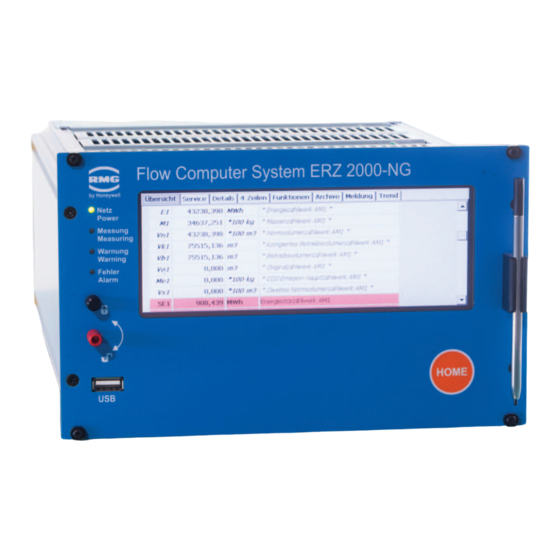
- Page 43 2 Introduction Figure 17: Display of the ERZ2000-NG in the browser Manual ERZ 2000-NG · EN07 · 2019, May 13th...
-
Page 44: Live Browser And Coordinate System
2 Introduction 2.2 Live browser and coordinate system Links have a tree structure that is comparable to Windows Explorer. The relevant menu is opened by clicking on one of the measurements, components, ... In the process, a symbol change from (bottom menu item) takes place and various sub-menus scan be selected by clicking , such as Overview, Absolute pressure, Gas temperature, etc. - Page 45 Top line: 1. RMG Messtechnik 2. ERZ2000-NG 3. 1.7.0 Consecutive number of the firmware version 4. 2013 Year of manufacture of the ERZ2000-NG 5. 1.1H Rail name EL 2 6. Gas1 p5 Measurement point EL 3 7. 123456… Serial number EK 3 8.
- Page 46 2 Introduction 4. Fault display By double-clicking on this field, the currently pending faults are displayed. 5. " " 6. M54-0 The fault messages are displayed in consecutive Calibr. lock order with fault number. 7. 1 Debug value (internal use) 8.
- Page 47 2 Introduction Windows in which additional, in-depth information of the selected parameter is shown are opened by clicking on the underlined text. Clicking on the Heading again will bring you back to the initial menu (Figure 18: Overview of measurements). The corresponding live values, their unit (if available) are behind the measurements and the corresponding coordinates are in the menu and the jump target.
- Page 48 2 Introduction Figure 22: Menu "AB Absolute pressure" The parameters on the right side belong to different categories, which is indicated with different colors, identification letters and other symbols in the left part on the right screen in the relevant line. The most important include: Dark yellow Display values, change not possible Beige...
- Page 49 2 Introduction found under AB Absolute pressure. These "points" are referred to as "coordinates" below. These individual coordinates are assigned additional meanings column-by- column: Col- Access col- Line num- Identification Alpha-num. Numerical Coordinate Value Corre- Variable Identifica- identifica- name sponding tion tion unit...
-
Page 50: Display
2 Introduction Note The method of counting takes place with letter / number combinations begin- ning with AA = first column 01 = first line Chapters belonging together are summarized under the first letters: AA, AB, AC, AD... / BA, BB, BC, ... / CA, CB, CC, CD ... Only the values that are relevant for the selected device type are displayed. - Page 51 2 Introduction Coordinate system Access au- Display thorization text Figure 24: Parameter display Explanation of symbols in the Access column: Display values, custody transfer, change not possible Parameter under single code word protection Special case: Code word entry/check General displays, display values, non-custody-transfer Parameters protected by official calibration Freeze value, not editable Parameter for, e.g.
- Page 52 2 Introduction Constant, not editable Imported measurement via Modbus, not editable Non-custody-transfer totalizers, CO volume at base cond., all disturb- ance totalizers, totalizers with an undefined billing mode, customer totalizers Automatically changing input value with simple code word protection Automatically changing input value without protection Parameter under super user protection Parameter under double code word protection Factory parameter can only be changed in the factory...
- Page 53 2 Introduction Automatically changing values that can be edited These values behave like changing values. Editing will change the initial value of these changing values, e.g. an offset. Example: Remaining time / trigger (KC06) for viewing the PTB telephone time service. KC06 contains the number of seconds until the next call of the telephone time service of the PTB.
- Page 54 2 Introduction Clicking on the arrow (in the red circle) opens a selection menu (here). DSfG Full minute In second 30 … The desired parameter can be selected from these default parameters. Note This pre-selection influences the choice of additional parameters. For example, if you choose a constant for the compressibility coefficient calculation, no ad- ditional parameters, such as calorific value, gas proportions, etc.
- Page 55 2 Introduction With the back arrow of Explorer Figure 30: Back to the main menu you return to the previous menu. In order to familiarize yourself with the settings options and the type of setting, we recommend testing the settings options in the various "menus" in this display with the mouse.
-
Page 56: Access Protection For Data And Settings
2 Introduction 2.3 Access protection for data and settings The ERZ2000-NG permits the entry and adjustment of all editable values. A descrip- tion is provided in chapter 2.2.1 Display. All editable values are access-protected, which prevents arbitrary changes. This access protection has different hierarchies... - Page 57 2 Introduction Without influence on measurement and measurement accuracy, Closed e.g. operating point testing resolution Without influence on measurement and measurement accuracy, Single code e.g. default values, warning limits, plausibility, comparisons, us- er protocols Adaptation of gas property tables, has influence on measure- ment, but is then permitted and desired.
- Page 58 2 Introduction Figure 33: Menu ED Access You can click on the fields after Code word 1 and Code word 2 and change the value of the code words with keyboard entry. If the rotating calibration lock is already open, the currently set code word can be read under the code words.
- Page 59 2 Introduction Deactivation of the access protection In the first line of the touch screen, you can display the access protection level under the "Login" tab. The calibration lock on the front panel is closed by turning it counter- clockwise. Note Normally, the calibration is now sealed by a calibration official.
-
Page 60: Basic Settings
2 Introduction 2.4 Basic settings Before further settings can be changed, some basic settings must be entered in the menu EE Display. For better representation of the actual content, only the right part of the screen is shown (here and in the following). Figure 34: Menu EE Display First, select the user language in the coordinate EE01 Language;... - Page 61 2 Introduction Note Depending on the user profile, only the menus and coordinates with the set- tings options corresponding to the access rights are available. The other men- us and coordinates are hidden. Recommendation: "Normal" customers select reader or user! The time after which the screen switches off following a period of inactivity is entered in the coordinate EE03 Screen saver.
- Page 62 2 Introduction Figure 35: EL Description site The menu EL Description site is provided essentially for storage of information about your measurement. Please fill out these fields completely by writing directly in them. Choose between main measurement and comparison measurement in the co- ordinate EL01 Measuring priority.
-
Page 63: Start Screen
The new numerical value and/or the new mode is adopted with "ac- cept". After the power is connected to the ERZ2000-NG, the start screen appears, which is visible in Figure 38: Start screen. Manual ERZ 2000-NG · EN07 · 2019, May 13th... - Page 64 The start screen shows all activated counters. If a counter is activated in the ERZ2000-NG, but no values are running, this counter is also displayed at the top with a volume flow Q = 0. The other counters become visible with vertical scrolling (right).
-
Page 65: Overview
2 Introduction 2.5.1 Overview If you scroll to the top in the overview or tap on the "Overview" menu item again; six selection fields appearing in the upper line can be used to switch to other tables, i.e. sub-menus. 2.5.1.1 Analysis Figure 39: Overview ->... - Page 66 2 Introduction 2.5.1.2 Measurements Figure 40: Overview -> Measurements sub-menu Measurements and resulting calculated values, such as pressure and temperature, as well as values such as density, calorific value, velocity of sound and viscosity are shown in this display. 2.5.1.3 Orifice plate Figure 41: Overview ->...
- Page 67 2 Introduction 2.5.1.4 Counters Figure 42: Overview -> Counters sub-menu This menu shows the various counters, a color underline assigns different times or other classifications to the counters. All 4 billing modes can also be activated as CO counters for energy-efficient monitoring. 2.5.1.5 Customer-specific counters (customer counters) Figure 43: Overview ->...
- Page 68 2 Introduction Figure 44: Menu: LA Overview Manual ERZ 2000-NG · EN07 · 2019, May 13th...
- Page 69 2 Introduction Figure 45: Menu: LB Totalizer BM1 Manual ERZ 2000-NG · EN07 · 2019, May 13th...
- Page 70 2 Introduction The counters of the 4 billings modes are summarized in the sub-menus LB Totalizer BM 1, LD Totalizer BM 2, LF Totalizer BM 3 and LH Totalizer BM 4 in the menu L Totalizers; the disturbance counters are located in the sub-menus LC Dist.
- Page 71 2 Introduction The quantity of the carbon dioxide arising from the combustion of natural gas with air is in coordinates LB16 – LB18. Menu LJ Tot. undef. BM also has a similar structure. Then this totalizer counts if the billing mode is invalid (e.g. in case of an incorrect switch position). Menu LK Counter parameters enables some important parameter adjustments.
- Page 72 The determination method for the channel status of the totalizers (DSfG function) is defined in LK26 Channel status method: a.) RMG traditional b.) New definition according to Ruhrgas with Method a.), all stationary counters have the stopped status, regardless of whether there is a fault or another route.
- Page 73 2 Introduction with Method b.), all counters have the stopped status and all main totalizers have the okay status in normal operation, regardless of whether they are running or not or whether another route is active. In case of an fault, all disturbance totalizers have the okay status and all main totalizers have the stopped status, regardless of whether they are running or not or whether another route is active.
- Page 74 2 Introduction The values of the different totlizers and their remainder can be set in coordinates LP02 Vc1 to LP67 DVx4 (e.g. Vc1 and Vc1R, etc.). A negative value means that this totalizer is not set. The coordinate LP99 Task defines the various assignments that can be viewed in the table below.
- Page 75 2 Introduction Figure 48: Menu LV Customer-specific totalizers set A The customer-specific totalizers have a similar configuration to the "normal" totaliz- ers. In coordinate LV31 Assignm. main/dist., a selection between "Undisturbed on- ly", "Disturbed only " and "Always" can be made for the Totalizers operation. With "Only undisturbed", for example, the customer totalizers only run when the ERZ2000- NG status is undisturbed.
- Page 76 2 Introduction 2.5.1.6 Flow rate Figure 49: Overview -> Flow rate sub-menu This menu shows different flow rates, such as energy flow, volume flow at base con- ditions and volume flow at measurement conditions or the measured flow. The aver- age flow speed is also displayed.
- Page 77 2 Introduction Figure 51: Overview -> System sub-menu Manual ERZ 2000-NG · EN07 · 2019, May 13th...
-
Page 78: Service
"Execute" in order to reset all parameters of WinCE to the default values (all parame- ters that are not under the calibration switch). If the ERZ2000-NG application is run- ning, a restart of the kernel is carried out as an essential part of the process and the CRC (cyclic redundancy check) of the complete kernel is calculated and displayed in Manual ERZ 2000-NG ·... - Page 79 Then the final setup of the ERZ2000-NG can take place. In the process, the network set- tings and time zone are stored in the device. The device is ready for operation when all necessary settings have been made.
-
Page 80: Details
2 Introduction 2.5.3 Details A list of all measurements, computed values, calculated variables, parameters, func- tions and operating modes is provided here. The data is shown in a structure like in the display with an internet browser; as viewed from the left, you see the superordi- nate menu tree, which can be opened by "clicking"... -
Page 81: Functions
Those accustomed to operating an ERZ2000 with device buttons have the possibility of also operating the ERZ2000-NG in this manner with this screen. The 4-line display of the ERZ2000 is also shown here. If operation via this "4 Lines" menu is selected, refer to the ERZ2000 manual in case of any questions. - Page 82 2 Introduction If display of the drag pointer is not desired, the appropriate setting can be made un- der EI16 Drag indic. active. 2.5.5.2 On-the-fly calibration Figure 58: "On-the-fly calibration" sub-menu under "Functions" Totalizers that can be started like a stopwatch at 0 are shown in this screen. It is started with "Enter"...
- Page 83 2 Introduction The type plate of the device is displayed in the "Type plate" submenu. This included further data, e.g. about the electronics (calibration kernel, Bios, WinCE kernel), about the totalizers and their settings (dimensions, pulse value), about the type of gas (composition, velocity of sound) and the environmental and base conditions (pres- sure, temperature).
- Page 84 The revision can be carried out at the same time in a partner device (ERZ2000 or ERZ2000-NG) which is connected to the same DSfG bus. For this purpose, the ap- propriate DSfG address of the partner device must be entered.
- Page 85 2 Introduction Figure 62: Menu FF Revision In order to receive logical values with appropriate resolution, an adequate test time must be provided. A few minutes are sufficient for the volume detection via the HF inputs, because synchronization of the test function with the recording of the volume frequency takes place.
- Page 86 2 Introduction FF07 Pre/post run Parameter for a relative specification of the run-up and after-run time, corresponding to the time between Time stamp 1 and 2 or 3 and 4 FF08 Delay Parameter for a wait time before the start with Time stamp 1 There are multiple processes for using the revision function.
- Page 87 2 Introduction Time stamp 1 Time stamp 2 Time stamp 3 Time stamp 4 Pre run Examination Post run Desig- 19-09-2018 19-09-2018 19-09-2018 19-09-2018 Unit Trend nation 16:01:26 16:01:36 16:02:36 16:02:46 Time 6400.967663 10.000063 6410.967726 59.999539 6470.967265 9.999886 6480.967151 43044.898303 0.326637 43045.224940 1.959824 43047.184764 0.326637 43047.511401...
- Page 88 This is referred to as a freeze. The last quantities and measurements are "frozen" with the freeze function. First, the ERZ2000-NG reports the recording of all data and the configuration of the table. This can take several seconds, then the data that was recorded on the specified date and time.
- Page 89 2 Introduction Figure 64: "Freeze" sub-menu under "Functions" Figure 65: Menu FC Freeze shows the submenu FC Freeze under "F Test". FC01 Time last freeze shows the time of the last archiving, coordinates FC03 to FC05 can be used to adjust when and how the freeze function is activated. FC04 de- fines the freeze time interval over which the data is recorded and archived.
- Page 90 2 Introduction No freeze processes are triggered Every second Freeze in second intervals Every minute Freeze in minute intervals at the start of a minute Every hour Hourly freezing at the start of an hour Every day Daily freeze at the start of the day Gas day Freeze is initiated on the specified gas day ("KA27 Gas day") at the beginning of the specified billing hour ("KA 14 Billing hour").
-
Page 91: Archive
2 Introduction 2.5.6 Archive The archive entries of all archive groups can be viewed in this screen. The entries are numbered from "Start" to "End", where the initial value is set to 1. If the index has reached the maximum buffer depth, the oldest entry is overwritten when a new data record is generated starting at this point. - Page 92 Up to 20 coordinates can be assigned in this manner. Entry for the user code is suitable for access. The ERZ2000-NG writes the result-controlled (e.g. with incoming and outgoing errors or with full hours or .. ) totalizer statuses, measurements and messages in its archive.
- Page 93 2 Introduction Figure 68: Free progarmmable archive Assignment to the archive: 4 control totalizers, 8 special measurement values and 6 special totalizers can be stored in Archive 10. Archive group 16, in which the free inputs can be stored, can be hidden in menu ID DSfG entity recording with "no"...
-
Page 94: Alarm, Warning Message
2 Introduction Figure 69: EM Erasing procedures menu Further details about the archive are provided in the appendix C) Archive assign- ment, depth and identification. 2.5.7 Alarm, warning message Figure 70: "Messages" All messages that have taken place since the last deletion are displayed in different colors in this field: Pending alarms, i.e. - Page 95 2 Introduction Light blue Notices ("H") of implausible parameterization or potentially faulty operating statuses. The notices can be converted to warnings and vice versa under coordinate JA07. Turquoise Messages ("M") normal operating statuses, e.g. "User lock is open". Gray Alarms or warnings that are temporary, have not been acknowl- edged, but are no longer present.
-
Page 96: Trend
2 Introduction … Figure 71: Acknowledgment of alarms and warnings 2.5.8 Trend Figure 72: "Trend" Overview The trend screen offers the option of graphical representation the time curve of a se- lectable value. For this purpose, a value and/or a position of the list must be selected in the upper part of the screen (Temperature, measured value, Absolute pressure, measured value, standard density, measured value, Density, measured value, Supe- rior calorific value, measured value, Carbon dioxide, normalized molar fraction, Nitro-... -
Page 97: Maximum Load
2 Introduction Value changes over time are displayed after activation of the trend screen. This sta- tus is recognizable in that the time displayed runs under the x-axis and the graph moves in the past to the left. It is possible to view the time curve in front of the displayed time range and to zoom in on the value range: The value of the measurement variable can be decreased or increased. - Page 98 2 Introduction 2.5.9.1 PB Maximum load display, maximum hourly value of the day Figure 74: Menu PB Maximum load display, maximum hourly value of the day Menu PB Maximum load display, maximum hourly value of the day is purely a display menu.
-
Page 99: Time System
KB Clock generator when the ERZ2000-NG is the source for the time signal. All displays and parameters required for reception of the signal are required in KC ext. time signal. - Page 100 "Entries". If necessary, the PC time can be adopted directly (by clicking). The internal real-time clock (RTC chip) of the ERZ2000-NG is operated with the world time UTC KA02 UTC. Consequently, the current location time KA01 Date and time is calculated and displayed with the offset according to the adjusted time zone.
- Page 101 2 Introduction Standard Time", the summertime changeover is activated automatically, on the con- dition that there is a statutory regulation for the time zone. Examples for time zone adjustment and for deactivation of summertime changeover. Germany With summertime changeover KA13 Time zone = "W. Europe Standard Time" KA03 Diff.
-
Page 102: Kb Time Contact Signal To External Devices
Figure 78: Menu KB Time contact signal to external devices The ERZ2000-NG can issue a time contact pulse in order to synchronize other de- vices. For this purpose, the length of the pulse can be adjusted in KB02 Time cont. -
Page 103: Kc External Time Signal
2 Introduction 2.6.3 KC external time signal Figure 79: Menu KC external time signal Coordinate KC01 Sync mode input determines the source and interpretation of ex- ternal time synchronization. The following options are available: DSfG Time synchronization is only expected and accepted via DSfG. Full minute The time contact takes place on the whole minute In second 30... - Page 104 2 Introduction Network SNTP Time is supplied from SNTP GPS 170 Time is supplied GPS To reference time Time is supplied from a reference Modbus Time is supplied from Modbus The following applies for the time contact options: Synchronization takes place on the rising flank. Polarity can be changed with NT04 Inverter mask of the contact inputs.
- Page 105 "heard", the value in KC06 is set to 90,000 seconds, i.e. the next call at- tempt takes place in 25 hours. If the number was busy or the time was not plausible, the value in KC05 (e.g. 300 seconds) applies and the ERZ2000-NG counts down to 0 and then attempts to call again.
- Page 106 The IP addresses for the Domain Name Service, i.e. DNS of the telecom are found in menu IA TCP/IP network. Note After a change of network settings, the network of the ERZ2000-NG must be switched off and on again for the settings to take effect. Manual ERZ 2000-NG · EN07 · 2019, May 13th...
-
Page 107: Kd Plausibility
2 Introduction GPS170 Synchronization takes place with a GPS reception module on COM 5. The following protocols are supported: Meinberg Std., NMEA, Computime, ABB SPA, Uni Erlangen, SAT, Racal. 2.6.4 KD Plausibility Figure 80: Menu KD Plausibility The ERZ2000 has 2 clocks - a long-term clock (hh:mi:ss /hours:minutes:seconds/ DD:MO:YY / day:month:year/) and a short-term clock that can be calibrated. -
Page 108: Electrical Connections
3 Electrical connections 3.1.1 Equipment variants The assignment of the connection terminals of the ERZ2000-NG is essentially speci- fied by the compact configuration. However, there are reserves, because a different definition of the terminal assignment is necessary depending on additionally installed extension modules. - Page 109 3 Electrical connections Figure 81: Menu EH Module assembly Manual ERZ 2000-NG · EN07 · 2019, May 13th...
-
Page 110: Configuration Of Connections
"COM 6 + 7" is not displayed in coordinate EH Module equipment. Device rear wall Since the ERZ2000-NG has a universal configuration, there are more connection terminals that required by the typical device (e.g. a status flow computer). There is a standard assignment of terminals that always use the first pins in consideration of numbering. - Page 111 3 Electrical connections Figure 83: Menu EI Configuration Manual ERZ 2000-NG · EN07 · 2019, May 13th...
- Page 112 The number of inputs and outputs to be connected is entered in coordinates EI01 to EI07. The ERZ2000-NG only enables and activates according to what is specified here. EI08 and EI09 contain the factory settings of the quartz frequency, which should not be changed.
-
Page 113: Terminal Assignment
3 Electrical connections 3.1.3 Terminal assignment Connection of supply voltage: Figure 82: Rear wall of the ERZ2000-NG (bottom left) X 16 24 V DC Fuse F1 = 2 A 1.0 A 24 W –10% / +15% Typical power con- Max. output... - Page 114 3 Electrical connections Terminal Current output 1 + Terminal Current output 1 - Terminal Current output 2 + Terminal Current output 2 - Terminal Current output 3 + Terminal Current output 3 - Terminal Current output 4 + Terminal Current output 4 - Terminal Input for Vo with external separator stage + Terminal 10...
- Page 115 3 Electrical connections Terminal 1 Signal input 1 + , assignment takes place with software Terminal 2 Signal input 1 - , assignment takes place with software Terminal 3 Signal input 2 + , assignment takes place with software Terminal 4 Signal input 2 - , assignment takes place with software Terminal 5 Signal input 3 + , assignment takes place with software...
- Page 116 3 Electrical connections With internal Ex- separator stage Ex1-NAMUR-2 / V1 or V2: (TÜV 06 ATEX 553139 X) ERZ2002/2102-NG; terminal X 8 is assigned for frequency measurement: Terminal 1 Signal input 6 + assignment takes place with software Terminal 2 Signal input 6 - assignment takes place with software Terminal 3 Signal input 7 + frequency input 5 density by software...
-
Page 117: Data Interfaces
3 Electrical connections Note With use of the internal Ex isolation stage: A mixture of inputs is possible with respect to Ex protection, which means an individual signal can also be used with an external isolation stage or with a pressure-proof encapsulated ignition protection type, in combination with Ex intrinsically safe protection type. - Page 118 Older USMs, DZU X 13 COM 3 Interface DSfG control station, 2 Modbus X 14 COM 4 Interface DSfG or RMG bus X 15 COM 5 Interface External modem X 37 COM 6 Interface Modbus master for reading the gas...
-
Page 119: Pin Assignment And Recommened Use Of The Interfaces
3 Electrical connections 3.1.5 Pin assignment and recommened use of the interfaces COM 1 Pin assignment Mode: RS 232 Mode: RS 422 Mode: RS 485 +U (+5V DC) +U (+5V DC) +U (+5V DC) TxD-A R/TA A Data RxD-A SGND Signal Ground TxD-B RxD-B R/TN B Data... - Page 120 3 Electrical connections Figure 84: IB Serial interfaces The operating mode for the COM 1 interface is adjusted in the menu IB Serial inter- faces with coordinate IB03 COM 1 operating mode. The mode can be set to: Modbus ASCII Test FLOWSIC600 (only internal)
- Page 121 3 Electrical connections Note If a FLOWSIC600 ultrasonic meter is connected, the operating mode of COM 1 must be adjusted to FLOWSIC600 and coordinate "IB25 FLOWSIC address" must be set to the Modbus address of the FLOWSICK ultrasonic meter. COM 2 Pin assignment Mode RS 232 The RS 232 cannot be switched with the DZU protocol occupied!
- Page 122 Modbus protocol or the DSfG control station. Note The DSfG interface implemented in the ERZ2000-NG conforms to the current version of the technical specifications of the DSfG for flow computers. The DSfG is required in the scope of this documentation (further documenta- tion is available from the DVGW).
- Page 123 IB09 COM 3 operating mode. The following adjustments are possible: Test DSfG RMG bus RMG bus-24K There is a separate description for the RMG bus. It is used together with RMG PGCs (GC 9000) instead of the DSfG. Manual ERZ 2000-NG · EN07 · 2019, May 13th...
-
Page 124: External Modem Connection
3 Electrical connections COM 5 (modem) Pin assignment Mode: RS 232 RS 232 with handshake plus carrier plus ring. Usable for MODEM (DFÜ). With connection of a modem, "Modem" must be selected in coordinate IB21 COM 5 operating mode. 3.1.6 External modem connection 1. - Page 125 However, if it is still available, it can be used as described. In case of inquiries about modem connection, contact the RMG service department. 3. Connection The ERZ2000-NG is connected to the external modem via a fully assigned RS232 cable, i.e. all 9 pins must be used 1:1. Note The modem connection does not work if only the minimum version is assigned with Pin 2, 3 and 5.
- Page 126 3 Electrical connections Example for a setting The setting must be made in the menu IE DSfG Remote data transmission access: IE06 Modem init. string ate0s0=1 IE07 Dial prefix atx3dt Figure 86: DSfG data transmission Meaning: Prefix of a command line Echo function deactivated s0=1 Set register 0 to 1, which means the number of alert characters after which the modem answers and establishes the connection, should be 1.
- Page 127 3 Electrical connections Figure 87: Menu: IB Serial interfaces The parameters for operation of the serial interfaces (also DSfG-B and Modbus) are adjusted in this menu IB Serial interfaces. The coordinate IB15 is an internal interface that can be used for the original Vo coun- ter of an encoder (ENCO).
- Page 128 3 Electrical connections IB16 contains the collective Timeout gas quality for gas composition. The register offset for the Modbus register is adjusted in IB17. The joint Modbus address for COM 1, COM 2, COM 3 and TCP/IP can be entered with IB18. With IB21, COM 5 can be configured for modem connection for "Modem"...
-
Page 129: Connections
3 Electrical connections 3.1.7 Connections 3.1.7.1 Inputs Input characteristics 2-channel HF volume flow input with pulse metering and frequency meas- urement The appropriate frequency input must be selected in this menu; Inputs 5, 6, 7 and 8 offer higher resolution. Channel 1: Volume measuring channel HF input Measuring range 0.10 Hz to 6.0 kHz... - Page 130 3 Electrical connections Volume input for digitally operating Vo counters Data transmission between the gas volume meter and flow computer take place uni- directionally and reactionless via a shielded, twisted pair of wires from the counter to the flow computer. The electrical characteristic data conforms to DIN 19234 (NAMUR).
- Page 131 6.8 V Reserve signal inputs The ERZ2000-NG offers additional free inputs for which the same data as for the "normal" signal inputs applies. These free inputs can be assigned with functions and events, statuses, additional counter, etc. can be detected and stored in DSfG ar- chives.
- Page 132 3 Electrical connections 3.1.7.2 Output characteristics Current outputs Quantity Range 0-20 mA or 4-20 mA Resolution 12 bit Ohmic resistance 700 Ω Overvoltage protection from 33 V, galvanically isolated Signal outputs Quantity U max 24 V DC P max 150 mW Ic max 100 mA 1.2V or Ron = 50 Ohm...
-
Page 133: Activation Of Inputs And Outputs
The required inputs and outputs can be activated in menu E Mode, submenu EI Con- figuration by a "Super user" (chapter 2.3 Access protection for data and settings). The number of activated inputs determines whether the ERZ2000-NG scans the cor- responding terminals in order to determine the measurement. If the value of the co- ordinate under EI Configuration is "0", no measurement takes place on this channel. - Page 134 3 Electrical connections Caution External Ex protection (Ex-d): Terminal X4, EI01 value = 1, EI31 value = 0 Caution Internal Ex protection (Ex-i): Terminal X10, EI01 value = 0, EI31 value = 1 Note F1, F2, F3 and F4 are combined with a pulse counter function for frequency in- puts and thus suitable for volume measurement.
-
Page 135: Assignment Of "Physical Values
3 Electrical connections 3.1.9 Assignment of "physical values" The assignment of physical values to the inputs and outputs is discussed in the fol- lowing chapters. 3.1.10 MA Input / output function key Figure 89: Menu MA Input / output function key Manual ERZ 2000-NG ·... - Page 136 3 Electrical connections The assignments of inputs and outputs are shown in menu MA Input / output function key. Inputs The assignment of inputs to "physical values" takes place in menus "A Measure- ments", "B Components", etc. The units of these measured variables are also defined in these menus in order to ensure correct transfer of the values.
- Page 137 3 Electrical connections Measurement value Original encoder counter Vc DZU (digital counter transmission) direction Flow direction (when switching from forwards/backwards) Transmission of analysis data (GC 1/2) or Modbus data If the billing mode is assigned to the original encoder counter Vo or a digital trans- mission takes place (e.g.
-
Page 138: Na Current Input 1
3 Electrical connections 3.1.11 NA Current input 1 Figure 90: Menu NA Current input 1 Current input 1 is shown here as an example for all current inputs. These current in- put menus are essentially display menus. Coordinate NA15 Beneficiary displays which function uses this measurement, i.e. -
Page 139: Ni Res. Input 1
3 Electrical connections 3.1.12 NI Res. input 1 Figure 91: Menu NI Res. input 1 Resistance measurement 1 is shown here as an example for all resistance meas- urements. These menus are essentially display menus. Coordinate NA15 Benefi- ciary displays which function uses this measurement, i.e. who is the beneficiary (the input is not used in this case). -
Page 140: Nl Frequency Input 1
The assessment and the unit must be entered here appropriately. The ERZ2000-NG has 4 pulse / frequency inputs. Usually frequency 1 and 2 are used for a turbine, but often (e.g. in case of Ultrasonic meter) they are unused. They may than be used for example for another flow rate meter. -
Page 141: Nt Contact Inputs
3 Electrical connections 3.1.14 NT Contact inputs Figure 93: Menu NT Contact inputs Assignment to "MRG" functions, measurement positions, etc. takes place with menu NT Contact inputs. Manual ERZ 2000-NG · EN07 · 2019, May 13th... -
Page 142: Nu Current Input 9 Exi
3 Electrical connections 3.1.15 NU Current input 9 Exi Figure 94: Menu NU Current input 9 Exi The additional NU Current input 9 and NU Current input 10 become possible with use of the Ex board. Note (Slots 11 and 12 are reserved for the 2nd Ex board). Manual ERZ 2000-NG ·... -
Page 143: Ny Resistance Measuremnt 3
3 Electrical connections 3.1.16 NY Resistance measuremnt 3 Figure 95: Menu NY Resistance measurement input 3 The additional NY Resistance measurement 3 becomes possible with use of the Ex board. NZ Resistance measurement 4 can also be used with the 2nd Ex board. Manual ERZ 2000-NG ·... -
Page 144: Mb Current Output 1
3 Electrical connections 3.1.17 MB Current output 1 Figure 96: Menu MB Current input 1 This current output channel 1 is shown as an example for all 4 current outputs. The main selection of the measurement takes place in coordinate MB05 Assign- ment. - Page 145 3 Electrical connections Warning If the physical value exceeds the defined value, a warning message is generat- The value in coordinate MB09 Averaging factor determines the smoothing of the current. A setting between 0 and 0.99999 should be adjusted in consideration of the following meaning: 0 (minimum) = smoothing deactivated 1 (maximum) = infinite smoothing.
-
Page 146: Mf Pulse Output 1
3 Electrical connections 3.1.18 MF Pulse output 1 Figure 97: Menu MF Pulse output 1 This pulse output 1 is shown as an example for all 4 pulse outputs. Data, calculated values, etc. can be selected with the various functions and mapped on the pulse out- put. - Page 147 The setting here should be "134". The pulse accumulation takes place in billing mode 1, 3 or 4. There is no accumulation in billing mode 2. The ERZ2000-NG offers the possibility to change the pulse length at the pulse out- puts. The coordinate E15 strategy is used for this purpose.
- Page 148 3 Electrical connections Figure 99: Transfer frequency “smooth” If the strategy "rough" is selected, all accumulated pulses are transferred as quickly as possible (e.g. at 100 Hz) at each transfer time point (here every 0.1 s). If the "soft" strategy is selected, the accumulated pulses are distributed evenly over the time interval.
-
Page 149: Mj Contact Output 1
3 Electrical connections 3.1.19 MJ Contact output 1 Figure 100: Menu MJ Contact output 1 Like before, MJ Contact output 1 is presented as an example for all contact outputs. The MJ03 Operating mode of the contact determines the source that switches the contact. -
Page 150: Mr Frequency Output 1
3 Electrical connections 3.1.20 MR Frequency output 1 Figure 101: Menu MR Frequency output 1 This frequency output is a help function in case the flow computer is also the main totalizer for a connected ultrasonic meter. A frequency signal is required from the ul- trasonic gas meter for pre-testing / calibration / test stand testing. -
Page 151: Revision Switch
3 Electrical connections 3.1.21 Revision switch When the revision is switched on, the pulse outputs are switched off in the ERZ2000- NG and the revision bit is set in the data records of the DSfG. In menu E Mode, submenu ED Parameter access, the revision switch can be switched from operation (normal operation, i.e. -
Page 152: Communication And Bus Systems
RMG bus Company protocol based on MODBUS. The PGC functions as master and the ERZ2000-NG as slave. Up to 32 slaves can re- ceive gas composition data in parallel via broadcasting. Protocol for ultrasonic flow meters If the measurement transmitter should be operated with HART protocol, the operating mode must be set to "Measurement value = Source value"... -
Page 153: Dsfg Bus
Familiarity with the normal DSfG documents is assumed in this manual. These doc- uments for users are listed in the appendix .J.1.1 Literature for the DSfG bus for addi- tional reference material. The DSfG functionalities realized in the ERZ2000-NG are implemented according to these requirements, i.e. in accordance with G485. - Page 154 ERZ2000-NG is the computing and/or registration instance COM 4 Modem IB21 ERZ2000-NG establishes a DSfG station access as a DFÜ unit An external modem should be connected to COM 5 COM 5 The DSFG bus is connected via COM 4 for a "normal" user.
- Page 155 Figure 103: DIL switches of COM 3 and COM 4 If the function of the control station is also activated in a ERZ2000-NG, a cable must also be routed to the start distributor from the COM 3 interface, wherein the corre- sponding DIL switches must be set.
-
Page 156: Modbus
There is a freely definable (configurable) range of 100 MODBUS registers in the ERZ2000-NG which can be pre-assigned with a factory setting (default) of 50 values of 4 bytes each. The contents of these 100 registers can be changed by the user at any time. - Page 157 4 Communication and bus systems Editing of the positions in the super block is simple; Modbus register 0 can be changed in menu II Modbus super block in coordinate II01 MB reg. 0 = ****. The assignment of the register to a variable can be selected under "value". Clicking on edit opens an additional menu with the option of selecting all data in the device (float- ing point variables and measurements) as a Modbus register and assigning it to an...
-
Page 158: Modbus Master Overview
4.3.2 Modbus master overview The ERZ2000-NG can receive the gas composition data from up to 2 process gas chromatographs (Fehler! Verweisquelle konnte nicht gefunden werden.). For this purpose, 2 Modbus masters have been implemented, which are listed in menus IL and IM (Figure 108: IL Modbus master for the PGC (gas analysis)). - Page 159 4 Communication and bus systems Serial interfaces PGC1 PGC2 COM6 COM7 TCP/IP network TCP/IP PGC1 PGC2 TCP/IP TCP/IP Figure 106: Connection of PGCs (gas analysis) A mixed constellation can also be adjusted, which means one PGC is coupled via a serial interface and the other via a TCP/IP network (see Figure 107: "Mixed"...
- Page 160 4 Communication and bus systems The Modbus master function is adjustable so that PGCs of other manufacturers can also be supported, e.g. a Siemens PGC. Figure 108: IL Modbus master for the PGC (gas analysis) shows the Modbus menu for a PGC. Figure 108: IL Modbus master for the PGC (gas analysis) A reduced graphic (Figure 109: Reduced graphic: IL Modbus master for the PGC) which shows only the essential content of the right window presents the...
- Page 161 7.6.4 IL Modbus Master. The various selectable streams are also ex- plained here. Register address The ERZ2000-NG has the default of the PGC register in the values of, e.g. IL01 Calorific value, wherein the desired value is found, e.g. Register 7020 for the calorific value in coordinate IL01.
- Page 162 F7020*3.6 Example addition rules It is possible that there is no entry field available in the ERZ2000-NG for a gas com- ponent measured by the PGC, such as cyclo-pentane in register 8290. In this case, the cyclo-pentane can be added to the share of another component, e.g. neo- pentane.
- Page 163 4 Communication and bus systems IL27 status For example, the following could be required for the PGC status: Value=1: The PGC measures without errors. Value=0: The PGC is in alarm. Value=0: The PGC is in revision. Note Only with value ≠ 0 the values of the gas quality are transferred. It is possible that a PGC does not provide the status in exactly this form.
- Page 164 4 Communication and bus systems served, i.e. parentheses must be used in both partial expressions. The com- plete expression for IL27 is (u10==0)&&(U2&4). Access Line Name Value Unit E § Status (u10==0)&&(U2&4) There are a total of 80 characters available for formulation of the expression. Expressions can consist of Arithmetic operators Addition +...
- Page 165 IL54 Slave accepts gaps This operating mode determines the manner in which the ERZ2000-NG sends its queries to the PGC. The key here is how the PGC reacts when unassigned Modbus registers ("gaps") are queried. The following options are available: The PGC sends an exception telegram when unassigned Modbus registers are queried.
- Page 166 The following options are available: Always Master 1 The ERZ2000-NG only works with a single PGC. Only Master 1 is active for query- ing of gas analysis data of the assigned PGC 1. Manual ERZ 2000-NG · EN07 · 2019, May 13th...
- Page 167 4 Communication and bus systems Always Master 2 In this case, the ERZ2000-NG only works with a single PGC. Only Master 2 is ac- tive for querying of gas analysis data of the assigned PGC 2. Contact The ERZ2000-NG can work with two PGCs. The selection of which of the two should be currently active takes place with a selectable input contact (see coordi- nate IL73 for the source).
-
Page 168: Namur Sensor Adjustment (Optional)
Figure 110: Menu: GU Namur sensor calibration Coordinates GU01 and GU02 offer 3 possibilities of carrying out the calibration: "Standard NAMUR" Standardized trigger threshold and hysteresis are loaded. "RMG tap" This is the factory setting. Special trigger threshold and hysteresis are loaded. "Manual adjust- Trigger value and hysteresis can be finely and roughly adjust- ment"... -
Page 169: Settings For Communication
ERZ2000-NG must be entered manually in coordinate IA01 own IP- Addr. Eth1 for network 1, e.g. "10.20.13.71". Under this address (or the automatical- ly assigned address), the ERZ2000-NG operates as an HTTP server and can be ac- tivated with a standard browser (Internet Explorer, Firefox) (see also chapter 2.1.3 Remote control / parameterization). -
Page 170: Ic Dsfg Instance Computer
4 Communication and bus systems The IA17 MTU Eth1 coordinate can be used to set the maximum packet size of the transmission protocol (MTU). This may be necessary if there are connection prob- lems (firewall, mobile radio, ..). Note Please only make these settings after consulting your IT department if there are connection problems (firewall, mobile phone, ...). - Page 171 The message numbers 1...999 are univer- sal messages. Higher numbers are assigned with manufacturer-specific messages. The range 5000...5999 was reserved and used for the ERZ2000-NG. For the mean- ing, refer to the documentation for DSfG events. The time stamp for the last event can be read under IC04.
-
Page 172: Id Dsfg Entity Recording
4 Communication and bus systems Note The complete data element list of the computer instance of the ERZ2000-NG is included in the device-internal documentation: see: Documentation/II DSfG/1. Data elements/a Computer 4.5.3 ID DSfG entity recording Figure 113: Menu: ID DSfG entity recording ID 01 Rec.entity address contains the DSfG address of the registering unit. - Page 173 The columns are overwritten with plain text, e.g. corrected volume at Name: meas. cond. totalizer AM1. Note The complete data element list of the registration instance of the ERZ2000-NG is included in the device-internal documentation: see: Documentation/II DSfG/1. Data element/b registration. Manual ERZ 2000-NG · EN07 · 2019, May 13th...
-
Page 174: Ie Remote Data Transmission Access
In general, the DFÜ is an independent device which simultaneously fulfills the func- tion of control station. This cannot be adjusted in the ERZ2000-NG. The reason is that two different data protocols cannot run on an interface at the same time. (The control station algorithm basically differs from a slave algorithm). - Page 175 This is Phase 4 of the login procedure. Hang up The telephone connection is disconnected. ERZ2000-NG wiring to modem. All 9 wires must be connected 1:1. All other variants are unsuitable. Manual ERZ 2000-NG · EN07 · 2019, May 13th...
- Page 176 The specification value "ate0s0=1" corresponds to the minimum requirement for the ERZ2000-NG to work with the modem. Meaning of the specification value: Hayes command prefix (prerequisite for each command) ECHO OFF: the modem should not repeat the received characters.
-
Page 177: If Dsfg Master
The port specification for the DSfG-B-IP interface is in coordinate IE16 DSfG-B-IP port. Note The complete data element list of the data remote transmission instance of the ERZ2000-NG is included in the device-internal documentation: see: Documentation/II DSfG/1. Data elements/c Data remote transmission. 4.5.5 IF DSfG master Figure 115: Menu: IE DSfG master Manual ERZ 2000-NG ·... - Page 178 4 Communication and bus systems IF01 DSfG de- The addresses of all participants on the DSfG bus are listed in coordinate vice. The following applies: Capital letters = external addresses Lower-case letters = internal addresses Participants found on the bus are displayed here even if the control station is not ac- tive.
- Page 179 4 Communication and bus systems Coordinate IF06 DSfG fault is an auxiliary quantity for the information transport of the lower DSfG protocol layers for fault evaluation. If parameter JD01 Software debug is set to "yes", the following messages are activated: H64-6 DSfG unex char.: unexpected characters in telegram H64-7 DSfG overflow:...
-
Page 180: Transmitters
5 Transmitters 5 Transmitters Various transmitters can be connected to the ERZ2000-NG. There are pre-settings for some of these transmitters which often do not require any adjustment or very little at all. By contrast, additional settings are required for other transmitters. The ordinary connection options and parameterization are presented. -
Page 181: Measurements
5 Transmitters 5.1 Measurements The measurements are listed in menu A Measurements. The first sub-item AA Overview displays some of these values in the live browser. Figure 116: Overview of measurements After clicking on AA Overview, the screen shown in Figure 116: Overview of measurements appears. - Page 182 5 Transmitters Figure 117: Explanation menu Windows in which additional, in-depth definitions and / or explanations of the select- ed parameter are shown are opened by clicking on the underlined text. Clicking on the Heading again will bring you back to the initial menu (Figure 116: Overview of measurements).
-
Page 183: Pressure Transducer
5 Transmitters … Figure 118: Listing of measurements By clicking on the parameter under the jump target, the corresponding menu ap- pears; e.g. clicking on the absolute pressure opens sub-menu AB absolute pres- sure (Figure 119: Menu AB Absolute pressure). Note With super user access, measurements such as pressure ("AB04"), tempera- ture ("AC04"), calorific value ("AD04"), etc. - Page 184 5 Transmitters Figure 119: Menu AB Absolute pressure The list of selectable pressure sensors is displayed in 3 columns instead of 1 central column. Manual ERZ 2000-NG · EN07 · 2019, May 13th...
- Page 185 With "enter" (below the table to the left, see Figure 119: Menu AB Absolute pres- sure), these values are specified in the ERZ2000-NG. The manufacturer and trans- mitter type and pressure range are adopted. The operating mode is defined with the...
- Page 186 5 Transmitters The manufacturer, serial number, etc. data will then appear automatically in the type plate display. Missing data can be written directly into the white fields. If you are not conducting official custody-transfer measurements, you can also connect other pres- sure transmitters.
- Page 187 5 Transmitters A 4..20 mA operating mode could also be selected for the chosen transmitter, then additional settings are necessary (definition of the measuring range, correction of characteristic curve, etc.). Other adjustment options can be selected for other transmitters with different trans- fers.
- Page 188 The correction value causes an offset shift. It is calculated from: Reference value mi- nus display value and is entered directly in the unit of the pressure. Example: value read on the reference device 20.00 bar, value displayed on the ERZ2000-NG 20.02 bar, result -0,02 bar This value must be entered in line 21 (Figure 119: Menu AB Absolute pressure) with the correct algebraic sign.
- Page 189 5 Transmitters Menu OB Overpressure shows the same display as AB Absolute pressure. This function is required if an overpressure transducer is used instead of the absolute pressure transducer. Then, the operating mode must be set to "from overpressure" in AB Absolute pressure.
-
Page 190: Temperature Transducer
5 Transmitters 5.3 Temperature transducer The gas temperature is displayed as menu "AC Gas temperature" as a second measurement value. Figure 124: Menu AC Gas temperature Manual ERZ 2000-NG · EN07 · 2019, May 13th... -
Page 191: Al Internal Temperature Of The Device
AL internal temperature of the device Figure 125: Menu AL internal temperature of the device The internal temperature of the ERZ2000-NG AL01 Measured value is measured near the analog/digital converter. The value can be output as a current out put for monitoring purposes. -
Page 192: Special Measurements
5 Transmitters 5.4 Special measurements Figure 126: Menu OF Special measurement 1 Free inputs (up to 8) can be assigned with signals in a similar manner to the custody- transfer-relevant measuring inputs. These must be treated analogously to all other measurement values (see above) in regard to their settings. -
Page 193: Flow Meters
6 Flow meters 6 Flow meters Basically, the ERZ2000-NG can work with all flow rate measuring devices that are used in the flow rate measurement of gas. However, the ERZ2000-NG offers the possibility of using pre-settings which can be adjusted with the measurement pro- cesses that are normally used. -
Page 194: Gb Flow Rate Parameters
6 Flow meters 6.1.2 GB Flow rate parameters Figure 128: Menu GB Flow rate parameters Manual ERZ 2000-NG · EN07 · 2019, May 13th... - Page 195 6 Flow meters Like pressure and temperature, the data of the gas meter which is used must be communicated to the computer and parameters such as type / manufacturer / serial number, etc. must be entered in the chapter Meters / flow rate parameters. This data will then appear automatically in the type plate display.
- Page 196 Multiple values can be adjusted in coordinate GB16 Vol.transd mode. This de- scribes how and how many independent flow rate measurement values are transmit- ted to the ERZ2000-NG. In the process, 1-C means a 1-channel and 2-C means a 2- channel transmission of flow rate values. The different transmission types are:...
- Page 197 The other flow rate data ("HF2-K 1/1" in this case) is stored in the archives and can be used for comparison or redun- dancy. Flow rate measuring devices from RMG typically transmit 3 values: RMG-typical : "HF 2-K 1/1, Vc"...
- Page 198 6 Flow meters Note It is not possible to operate two independent volume measurements with two volume transmitters. Available for selection in GB16: LF1-ch. Single-channel operation with LF input only counting, no flow rate, there is no lower shut-off limit (leak flow volume) HF1-ch.
- Page 199 6 Flow meters and 3). With synchronization errors, a warning message is triggered and a switchover to the plausible input takes place. Vo, HF2-ch. X/Y Vm is calculated from Vo, HF inputs are used for compari- son, checking for synchronization and calculation of the flow rate (selection 1 of 3).
- Page 200 Vo and LF input. The following table provides an overview of the functions in error-free operation. In case of an error, the ERZ2000-NG uses the undisturbed signal or, with 3 input signals, it automatically switches over to the appropriate signal.
- Page 201 6 Flow meters Coordinates GB17 to GB20 are used for comparison of two frequencies. The first GB17 Start-up pulses are not considered for the comparison. This is especially criti- cal with a 2-channel volume measurement, which is based on different frequencies. The monitoring is only activated after the expiration of the GB17 Start-up pulse.
- Page 202 GB33 Better HF channel must deliver the better value before a changeo- ver takes place. Coordinate GB35 Decision change indicates how often the ERZ2000-NG has selected the other channel. Whether the alarm output of third-party volume transmitters is activated can be de- fined in GB37.
-
Page 203: Gc Kv Factor
6 Flow meters If no real volume transmitter is available, a turbine with the frequency adjusted in GB55 can be simulated for test purposes. For this purpose, the setting must be ad- justed to "sim. turbine freq." in operating mode GB16 Volume transmitter mode. 6.1.3 GC kv factor Figure 130: Menu GC kv factor... -
Page 204: Gd Characteristic Curve Determination
= const. are the greatest. With flow rate meters which have minor variance of the characteristic, 4 interpolation points, which are offered with "RMG support point" are used. Manual ERZ 2000-NG · EN07 · 2019, May 13th... - Page 205 "Polynomial Q RMG" describes the typical characteristic curve for RMG meters. With "Polynomial Re RMG", a Reynolds-number dependency is also taken into considera- tion.
-
Page 206: Ge Error Curve Linearisation, Forward Flow
6 Flow meters 6.1.5 GE Error curve linearisation, forward flow Figure 132: Menu GE Forward operation characteristic curve correction Manual ERZ 2000-NG · EN07 · 2019, May 13th... - Page 207 6 Flow meters There are 16 support point pairs for forward operation and the polynomial coefficients (at the end of the table). If "without correction" is entered in GD07 for GD Determina- tion of characteristic, the values still used again without correction. This corre- sponds to the value "0"...
- Page 208 Note The entry of the interpolation points can be carried out in any arbitrary se- quence; the ERZ2000-NG sorts them automatically. Characteristic curve correction with polynomial, relative to the flow rate The correction takes place with a 4th degree polynomial which represents the error curve of the gas meter depending on the flow rate.
- Page 209 6 Flow meters Error equation: 353677 Reynolds number equation: Where = error curve deviation [%] = Reynolds number = constants = Viscosity (Menu AM Viscosity, as a constant for natural gas = 12 * 10 The polynomial coefficients A (n = -2, -1, 0, 1, 2) are calculated from the measured value pair error F and Reynolds number Re Re,i...
-
Page 210: Gg Flow
GG Flow Figure 134: Menu GG Flow The value from the data sheet of the meter must be entered in GG04. The other val- ues are calculated by the ERZ2000-NG. 6.1.7 GH Start-up and shut-down monitoring Figure 135: Menu GH Start-up and shut-down monitoring The current status is shown in GH01. -
Page 211: Hb Energy Flow
6 Flow meters 6.1.8 HB Energy flow Figure 136: Menu HB Energy flow The energy flow can be checked in this menu. Warnings can be adjusted if limit val- ues are undercut (HB06) or exceeded (HB07). All other values are provided strictly for display purposes. A drag pointer indicates the minimum or maximum which arose during the last measurement period. -
Page 212: Oo Extra Counter
6 Flow meters 6.1.9 OO Extra counter Figure 137: Menu OO Extra counter 1 Free inputs (up to 8) can be assigned with signals in a similar manner to the custody- transfer-relevant measuring inputs. These must be treated analogously to all other frequency inputs (see chapter 3.1.13 NL Frequency input ) in regard to their set- tings. -
Page 213: Turbine Meter
6 Flow meters 6.2 Turbine meter The operating method of turbine meters is based on the measurement of gas speed with a turbine wheel. In the process, the speed of the turbine (approximately) within the measuring range (Q ) is proportional to the mean gas speed and thus the flow rate. -
Page 214: Ec Billing Mode
EC Billing mode Figure 139: Menu EC Billing mode The ERZ2000-NG has different totalizer sets which can fulfill different tasks, e.g.: Some gas flow meters can determine volume flow forwards and backwards with the same accuracy. Then, the totalizer can be used in forward and back-... - Page 215 6 Flow meters Various billing modes can be adjusted in coordinate EC04: Bill.mode 1 Bill.mode 2 Bill.mode 3 Bill.mode 4 1 ctc. 2*BM 2 ctc. 2*BM 2 ctc. 4*BM 4 ctc. 4*BM Modbus Meas.->2BM Meas.->3BM Meas.->4BM Vo Direction DZU Direction Flow direction GC1/GC2 With selection of the first 4 pionts (billing mode 1, 2, 3, 4), the respective billing mode...
- Page 216 6 Flow meters Route 1 is assigned (V1 closed, V2 open Route 2). All positions of the valves be- tween them, e.g. which can be provided for changeover, are not assigned to any bill- ing mode. The other contact options can be assigned in a similar manner: 2 ctc.
- Page 217 6 Flow meters The DZU Direction and flow direction can be used in the same manner as the Vo Di- rection. GC1/GC2 GC1/GC2 can be used, for example, if two different gas anlysis devices are in use, e.g. a full analysis device like the PGC9300 and a calorific value measuring device like an EMC.
- Page 218 6 Flow meters Figure 140: Menu LN Original totalizer The menu is intended primarily for display purposes. An automatic entry of the type plate data is made in LN10 Manufacturer to LN15 Vo tot. unit, as long as the transmitter provides this data in the frame of the telegram defined for this purpose. The behavior with a Vo transducer rotating in reverse is defined in coordinate LN16 Vo direction mode.
-
Page 219: Ultrasonic Gas Meter
6 Flow meters 6.3 Ultrasonic gas meter Figure 141: 2 Transducers form a path for the measurement shows the basic princi- ple. Transducers TD1 and TD2 are available for the measurement and form a meas- uring path with the distance L. An ultrasonic pulse is transmitted – with flow – on the measuring path back sensor TD1 to transducer TD2 faster than vice versa. - Page 220 In order to consider the flow profile, particularly an asymmetrical or heavily swirling flow, a total of 6 paths are measured on 3 levels with ultrasonic meters from RMG. The 3 levels can be derived mathematically with an integration process, called Gauss integration.
- Page 221 6 Flow meters Other manufacturers have, in part, implemented different path arrangements; howev- er, the further expansion is normally carried out in a similar manner. The individual mean path speeds are weighted and add up according to the Gauss quadrature. Multiplication by the pipe cross-section produces the volume flow. Quality of the installation situation Ultrasonic meters provide parameters which permit an assessment of the installation situation.
- Page 222 6 Flow meters Profile and symmetry factory With a fully developed flow, the middle paths (3 + 4) have the highest prevailing speed, the two outside paths (1 + 2; 5 + 6) have about the same speed. The profile factor (PF) is typically between 1.05 and 1.20;...
-
Page 223: Gj Body Compensation
6 Flow meters 6.3.1 GJ Body compensation Figure 143: Menu GJ Body compensation In menu GJ Body compensation, an expansion of the meter housing and thus a change to the inside diameter can be considered as a function of the temperature and pressure. -
Page 224: Ua Ultrasonic Volume Transmitter
This and the following menus define the operation of an ultrasonic meter (IGM), which only assumes a small part of the signal evaluation and further processing. The ERZ2000-NG assumes the majority of these tasks. The sensor signals of the IGM measuring heads are connected via a Modbus con- nection directly to the flow computer in this operating mode. -
Page 225: Ub Usz Reynolds Correction
6 Flow meters When one of the 4 possible device versions has been selected (ERZ2004 USC, ERZ2104 USC, ERZ2002 USC or ERZ2102 USC), additional function units must be considered. In recent years, some new ultrasonic meters have been introduced to the market, with which this further processing is an integral component of the electronic evalua- tion. -
Page 226: Uc Base Correction
6 Flow meters 6.3.4 UC Base correction Figure 146: Menu UC Base correction This correction is – if necessary – implemented by new ultrasonic flow rate meters and does not have to be used again here. It can be used with the IGM; refer to chap- ter 6.3.2 UA Ultrasonic volume transmitter. -
Page 227: Ue Effects Of Correct
6 Flow meters This correction is – if necessary – implemented by new ultrasonic flow rate meters and does not have to be used again here. It can be used with the IGM; refer to chap- ter 6.3.2 UA Ultrasonic volume transmitter. 6.3.6 UE Effects of correct. -
Page 228: Uf Id Display Igm 1
6 Flow meters 6.3.7 UF ID display IGM 1 Figure 149: Menu UF ID display IGM 1 These functions provide detailed information about the IGM ultrasonic transmitter, its sensors and their behavior. An exact description of the meaning of the individual fields is provided in the separate documentation ERZ_2000_USC_Details. -
Page 229: Uj Path 1
6 Flow meters 6.3.8 UJ Path 1 Figure 150: Menu UJ Path 1 This menu shows details of the display and parameterization for measuring path 1 of an IGM Ultrasonic meter; therefore, refer to chapter 6.3.2 UA Ultrasonic volume transmitter. The following menus have the same layout for measuring paths 2, 3, 4, 5, 6, 7 and 8. -
Page 230: Vb Speed Of Sound
6 Flow meters The flow speed is determined along the measuring paths. This menu shows these individually and as a mean value for measuring paths 1-8 of an IGM Ultrasonic meter; therefore, refer to chapter 6.3.2 UA Ultrasonic volume transmitter. 6.3.10 VB Speed of sound Figure 152: Menu VB Speed of sound... -
Page 231: Vc Ultrasonic Profile
6 Flow meters 6.3.11 VC Ultrasonic profile Figure 153: Menu VC Ultrasonic profile of velocities Additional profile specifications can be calculated from the various path speeds and displayed in this menu for an IGM ultrasonic meter. Refer also to chapter 6.3.2 UA Ultrasonic volume transmitter. -
Page 232: Ve Messages
6 Flow meters 6.3.13 VE Messages Figure 155: Menu VE Messages This menu shows error messages and status information of an IGM ultrasonic meter; see chapter 6.3.2 UA Ultrasonic volume transmitter. 6.3.14 VF Signal acceptance Figure 156: Menu VF Signal acceptance Manual ERZ 2000-NG ·... -
Page 233: Vg Signal-To-Noise Ratio
6 Flow meters This menu shows the quality in the determination of path speeds of an IGM ultrasonic meter; see chapter 6.3.2 UA Ultrasonic volume transmitter. 6.3.15 VG Signal-to-noise ratio Figure 157: Menu VG Signal-to-noise ratio This menu shows the signal quality in the run-time determination; the signal-to-noise ratio f the ultrasonic sensors of an IGM ultrasonic meter is specified;... -
Page 234: Vh Automatic Gain Control
6 Flow meters 6.3.16 VH Automatic gain control Figure 158: Menu VH Automatic gain control This menu shows the automatic gain control (AGC) that is applied to the measure- ment paths up- and downstream; see chapter 6.3.2 UA Ultrasonic volume transmitter. 6.3.17 VI Gas speed hourly mean value Figure 159: Menu VI Gas speed hourly mean value... -
Page 235: Lo Digital Totalizer Transmission
6 Flow meters This menu shows the hourly mean value of the individual speeds and that of the means value of an IGM ultrasonic meter; see chapter 6.3.2 UA Ultrasonic volume transmitter. 6.3.18 LO Digital totalizer transmission Figure 160: Menu Digital totalizer transmission Display of diagnostic information associated with a connected US 9000 computer with main totalizer function. -
Page 236: Connection Of Uszs Via Instance F
This Modbus protocol is frequently already called Instance F, alt- hough it is only prepared for the data required for the DSfG Instance F. In the ERZ2000-NG, the appropriate settings are found in menu VK Modbus master USM. The corresponding register plots are provided in menu VJ Register expressions. -
Page 237: Modbus Communication With The Usm Gt400
Electrical connection Figure 162: Connection of the Modbus interface of the USM to COM 6 shows the rear wall of the ERZ2000-NG. The USM GT400 is connected to serial interface COM6. Figure 162: Connection of the Modbus interface of the USM to COM 6 6.4.4... -
Page 238: Configuration For Com6 And Com7
6.4.5 Configuration for COM6 and COM7 The optional COM 6 interface is required by the ERZ2000-NG for communication with ultrasonic meters via Instance F. The DIL switches and jumpers for the RS 485 on the optional board required for this purpose must be adjusted as shown in Figure 164: Option board configuration for use as COM6 and 7. - Page 239 6 Flow meters Figure 164: Option board configuration for use as COM6 and 7 Figure 165: Slot of the option board for COM6 and 7 Manual ERZ 2000-NG · EN07 · 2019, May 13th...
- Page 240 Figure 165: Slot of the option board for COM6 and 7 shows the rear side of the ERZ2000-NG on the left. Figure 166: Jumpers for COM6 and COM7 on the rear wall shows the rear side of the ERZ2000-NG at the bottom.
- Page 241 6 Flow meters Figure 167: Interface module C34 Manual ERZ 2000-NG · EN07 · 2019, May 13th...
- Page 242 6 Flow meters The magnification of the right (upper) image cutout shows how to set the jumpers. Figure 168: Jumper COM6/7 on the rear wall Manual ERZ 2000-NG · EN07 · 2019, May 13th...
-
Page 243: Volume Transmitter Operating Mode
6 Flow meters 6.4.6 Volume transmitter operating mode If "DSfG: F instance COM6/7" under this button is activated under this in menu GB Flow rate parameters, the additional necessary settings are recommended in this menu (bright yellow-green background): GB16 Volume transmitter mode ►... -
Page 244: Protocol Type In Menu Vj Register Plots
6 Flow meters 6.4.7 Protocol type in menu VJ Register plots After selection of volume transmitter "DZU", the protocol type "DSfG: F Instance ("1") must be defined by pushing a button in menu VJ Register expressions. Then the appropriate registers for Modbus communication are recommended. …... -
Page 245: Com6 Interface Configuration
6 Flow meters The connection and selection of all other listed ultrasonic meters are also permissible for official custody-transfer applications. Then, the recommendation which was entered is shown in coordinate VJ98 Used button. Note Caution: Even if, for example, the "swirl" information is transmitted in the same field with the same register, the "swirl"... -
Page 246: Configuration Vk Modbus According To Instance F
6 Flow meters Figure 172: Modbus serial C7 operating mode Figure 173: Operating mode off 6.4.9 Configuration VK Modbus according to Instance F For communication via DSfG Instance F, VK Modbus master USM must be parame- terized in accordance with DSFG Instance F specifications, as shown in Figure 174: Configuration of Modbus master USM according to Instance F. -
Page 247: Configuration Menu Vk For Usm Gt400 Rs 485-1
If the interface RS 485-1 for data communication is selected on the USM GT400 with the ERZ2000-NG via Instance F protocol, different settings of the Modbus master USM in column VK are required due to the non-parameterizable byte sequence for the data types long and float. -
Page 248: Configuration Usm Gt400 For Instance F
Configuration USM GT400 for Instance F Serial interface RS 485-2 (opt. Ser2) If the ERZ2000-NG is configured in accordance with DSfG Instance F specifications, as described in chapter 6.4.9 Configuration VK Modbus according to Instance F, the USM GT400 must be connected to the RS 485-2 interface. This is located in coordi- nates J-25 to J-37 under the designation "Opt. - Page 249 1, which must then be selected if the standard value -1 is the setting in the ERZ2000-NG in VK63. In addition, the freely programmable Modbuss address in J-20 of the USM GT400 must also be used in the ERZ2000-NG in coordinateVK52. Figure 177: Parameterization of RS 485-1 for Modbus in accordance with In- stance F Manual ERZ 2000-NG ·...
-
Page 250: Modbus Register For Instance F
6 Flow meters 6.4.12 Modbus register for Instance F Modbus register list The following table actually represents a DSfG data element list (DEL). It is manufac- turer-independent and describes the data storage and/or data elements of a type of ultrasonic meter. The data elements were numbered starting from 8000h in a suitable manner for the Modbus. - Page 251 6 Flow meters Path-dependent values of path 1 (current values) 32896 float Path speed [m/s] 32898 float Speed of sound [m/s] 32900 float Signal acceptance 32902 float Signal-to-noise ratio AB [dB] 32904 float Signal-to-noise ratio BA [dB] 32906 float Automatic amplification AB [dB] 32908 float...
- Page 252 6 Flow meters 32964 float Signal acceptance 32966 float Signal-to-noise ratio AB [dB] 32968 float Signal-to-noise ratio BA [dB] 32970 float Automatic amplification AB [dB] 32972 float Automatic amplification BA [dB] 32974 float reserved, always = 0 Path-dependent values of path 6 (current values) 32976 float Path speed...
- Page 253 6 Flow meters Display of Instance F measurement values and status informations The Modbus register list is implemented in both the ERZ2000-NG in menu VJ Regis- ter expressions and in the USM GT400 in menu BA (Figure 178: Menu BA Instance F in the USM GT400).
- Page 254 The corresponding measurements and status information are displayed in the ERZ2000-NG with closed calibration switch; the Modbus addresses are displayed with closed calibration switch (Figure 179: Modbus register list in the ERZ2000-NG with closed (left) and opened (right) calibration switch).
-
Page 255: Ox Rmgview Trigger
6.4.13 OX RMGView Trigger Figure 181: Menu OX RMGView trigger The ERZ2000-NG can be coupled to an external computer via Modbus exclusively for internal purposes. The internal PC user interface "RMGView " visualizes the device data and enables remote parameterization. -
Page 256: Orifice Plate Diameter
6 Flow meters 6.5 Orifice plate diameter Flow rate measurement with a reduced flow cross-section is a prevalent method used for fluids, vapors and gases. In generally, it is a very durable method with which very high accuracy can be achieved with the requisite effort. The method is used in official custody transfer applications and is often used as a reference for other methods. - Page 257 Orifice plates should not be operated under 50 mm and with Reynolds numbers under 5000 (both relative to the inside pipe diameter). The ERZ2000-NG must be switched over to a suitable type before an orifice plate measurement takes place (see chapter 1.5.1 Device type adjustment). The "orifice plate"...
-
Page 258: Ga Tube Dimensions
6 Flow meters 6.5.1 GA Tube dimensions Figure 183: Menu GA Tube dimensions Menu GA Tube dimensions enables settings of the orifice plate parameters (for the ERZ2014-NG, ERZ2114-NG, ERZ2012-NG and ERZ2112-NG). The neck is defined at 20°C in coordinates GA07 and GA08. The temperature correction of the orifice plate diameter and the inside pipe diameter takes place in accordance with VDI/VDE 2040, sheet 2 (chapter 10) of April 1987. - Page 259 6 Flow meters GA10 Substance orifice GA11 Substance pipe Coefficients Selection options Linear GOST Steel I 12.60 0.0043 Steel II 12.42 0.0034 Steel III 12.05 0.0035 Steel IV 10.52 0.0031 Steel V 17.00 0.0038 Steel VI 16.30 0.0116 Bronze SnBz4 17.01 0.0040 Copper E-Cu...
- Page 260 6 Flow meters The coefficients in Table 7: Temperature correction for orifice plate and pipe are as- signed automatically with selection of a material. The permissible temperature range for the listed materials extends from -200°C to 600°C; the maximum temperature for copper, nickel and brass is 500°C.
-
Page 261: Ap Diff.pressure
6 Flow meters 6.5.2 AP diff.pressure Figure 184: Menu AP differential pressure Manual ERZ 2000-NG · EN07 · 2019, May 13th... - Page 262 The evaluation of signals can take be analog or digital (HART). The measuring cells are preferably operated in transmitter mode. For this purpose, the ERZ2000-NG provides the 24 V DC supply voltage.
- Page 263 The value in coordinate AP12 Zero point noise specifies the differential pressure that should be suppressed by ERZ2000-NG (the effect corresponds to a leak volume limit, see chapter 6.1.2 GB Flow rate parameters).
- Page 264 Note For the optimal operating mode of the ERZ2000-NG as an orifice flow me- ter, the second A/D converter available in the device is commissioned in order to ensure a quick delta-p measurement in parallel to the measure- ment of pressure and temperature.
-
Page 265: Special Case Zero Point Calibration Of All Delta-P Cells
6.5.3 Special case zero point calibration of all delta-p cells The ERZ2000-NG provides a function for offset correction with flow rate zero in the orifice plate computer operating mode. This makes a simple calibration of a zero point drift of the delta-p cells possible. - Page 266 6 Flow meters Menu GV Orifice shows some of the adjusted and calculated values. Serial number of the orifice meter Figure 185: Menu GV Orifice Corner, flange or D-D/2 can be selected for coordinate GV10 tapping. In GV11 method of calc., all various data is based on ISO5167 the last is from the 2003.
- Page 267 6 Flow meters Menu GV Orifice plate shows some GW Extremal values of the Orifice calculation for an expanded type plate. GW01 shows the flow rate coefficient C and GW02 shows the Reynolds number Re in the design point of the orifice meter. GW04 and GW05 contain the maximum mass flow rate and the maximum flow rate at base con- ditions.
- Page 268 6 Flow meters The correction of the pipe roughness and the abrasion of orifice edge takes place according to the requirements of GOST 8.586 for the flow rate and quantity meas- urement of fluids and gases with normal throttle devices, as described in chapter 6.5.1 GA Tube dimensions.
-
Page 269: Parameter Of The Gas
7 Parameter of the gas 7 Parameter of the gas Various physical properties of the gas which make the detection and determination / calculation more elaborate than the flow rate determination of liquids must be taken into account for the flow rate measurement of gases. The key parameters for the flow rate measurement of gases are summarized below;... - Page 270 Default Default Default Default DSfG DSfG DSfG DSfG RMG bus RMG bus RMG bus Polynomial 1st order Polynomial 1st order Polynomial 1st order Polynomial 2nd order Polynomial 2nd order Polynomial 2nd order Polynomial 3rd order...
-
Page 271: Bb Carbon Dioxide
7 Parameter of the gas 7.1.2 BB Carbon dioxide Figure 191: Menu BB Carbon dioxide Manual ERZ 2000-NG · EN07 · 2019, May 13th... -
Page 272: Be Methane
7 Parameter of the gas Many parameters already presented in the preceding chapters have not been ex- plained yet. Lines 2 and 5 are linked together; a default value can be entered in line 5, which is then taken as a basis if the value runs beyond the alarm limits. Since the operation mode is set to default, the source is switched off;... -
Page 273: Additional Gas Values
7 Parameter of the gas Methane has the greatest share in natural gas, in which can be up to 99 %. The dis- play here also has a similar layout to the display for CO , but it is reduced to the es- sential elements. -
Page 274: Ad Superior Calorific Value
7 Parameter of the gas 7.2.1 AD Superior calorific value Figure 193: Menu AD Superior calorific value Manual ERZ 2000-NG · EN07 · 2019, May 13th... - Page 275 AD05, because the operating mode is set to "default". A different operating mode can be selected in AD03 (e.g. from default, DSfG, RMG bus, lin. fre- quency response, 1st order polynomial, 2nd order polynomial, 3rd order polynomial, 4-20mA coeff., 0-20mA coeff., 4-20mA limit value, 0-20mA limit value, table value,...
-
Page 276: Ae Standard Density
7 Parameter of the gas 7.2.2 AE Standard density Figure 195: Menu AE Standard density Manual ERZ 2000-NG · EN07 · 2019, May 13th... -
Page 277: Lu Quantity Weighted Average Values
7 Parameter of the gas The 2 source can be selected under AE20 for standard density transmitters with 2 frequencies. Further explanations can be omitted, because the menu has the exact same structure as the previous menu. 7.2.3 LU Quantity weighted average values Figure 196: Menu LU Quantity weighted average values Quantity-weighted mean values are formed for superior calorific value, standard den- sity and density. -
Page 278: Af Relative Density
7 Parameter of the gas 7.2.4 AF Relative density Figure 197: Menu AF Relative density The density of air is set to the value d = 1 for the density ratio. Light gases (such as = 0.07], methane [d = 0.553], ...) have a value less than 1 (d <... -
Page 279: Aj Velocity Of Sound At Measurement Conditions
7 Parameter of the gas 7.2.8 AJ Velocity of sound at measurement conditions The velocity of sound is based on the present conditions (density or pressure and temperature). Due to the identical structure of the preceding menus, no further repre- sentations and explanations are provided here. - Page 280 7 Parameter of the gas Note The Joule-Thomson coefficient μ can be positive or negative. For air, the tem- perature increases with a pressure increase (heating up of the valve with an air pump) and decreases as pressure decreases. With natural gas, the Joule- Thomson coefficient μ...
-
Page 281: C Analysis
7 Parameter of the gas 7.3 C Analysis The gas analysis specifies various gas models that can be used in the ERZ2000-NG. There are brief explanations of when the various models are and should be used. These models are provided to enable calculation of the derived values. -
Page 282: Cb Conversion Factor
7 Parameter of the gas Some of the adjusted and used data for gas calculation is specified in the overview: The adjusted method for calculation of gas parameters – in this case, AGA 8 92DC Value of the K coefficient Value of the status coefficient Value of the Z coefficient Volume shares of various gas components... -
Page 283: Cc Calculation Of K Coefficient
7 Parameter of the gas 7.3.3 CC Calculation of K coefficient Figure 200: CB Calculation of K coefficient The selection of the gas model, i.e. the calculation method for determination of the compressibility coefficient (K coefficient) used for determination of the official custo- dy-transfer results takes place in CC05 Calc. - Page 284 7 Parameter of the gas GERG 88 S set B GERG 88 S set C AGA8 Gross Meth.1 AGA8 Gross Meth.2 AGA NX 19 L AGA NX 19 H In order to be able to apply GERG 88 S, the calorific value (Hs) and standard density (sd) of the gas must be known and the share of carbon dioxide (CO ) and the share of hydrogen (H...
- Page 285 7 Parameter of the gas AGA 8 92DC is currently chosen for "normal" natural gas (status 2017). GC1/GC2 GC1 / GC2 means that the K coefficient method follows the respective active meas- uring device in case of a redundant addition of the gas characteristic. Example: The main measurement with a GC takes place with a full analysis and the K coeffi- cient is calculated according to AGA 8 92 DC.
- Page 286 7 Parameter of the gas Pipeline Quality Gas Pipeline Quality Wider Ranges (<10MPa) Gas (<12MPa) of Application Value Unit 48 MJ/m3 350 K 65 MPa 0.55 0.55 0.55 90 - Methane 100 mol-% 50 mol-% 30 mol-% Ethane 20 mol-% Propane 5 mol-% 0.015...
- Page 287 7 Parameter of the gas If the current operating conditions are not adequate for "Wider ranges of application", this is also indicated here. Then a quality statement cannot be made. In case of a violation of a pre-selected quality range, the message "H80-3 AGA8<>range"...
-
Page 288: Gerg 88 S
7 Parameter of the gas 7.3.4 GERG 88 S Figure 201: Menu CD GERG 88 S CD06 Consistency check determines and displays deviations in the selected calcu- lation method (AGA 8 92 DC in this case). Exceeded limit values are monitored in Germany exclusively with use of GERG 88 S. CD07 Limit mode can be used to determine how further calculation takes place in case of a limit value breach. - Page 289 0.55 to 0.9 Hs of 20 to 48 MJ/m³ of 0 to 30 Mol% of 0 to 10 Mol% "very wide" (corresponding to RMG-internal definition): T of -15 to 70°C P of 0 to 150 bar dv of 0.38 to 1.16 Hs of 10 to 60 MJ/m³...
-
Page 290: Ce Aga Nx 19 Equation Of State
7 Parameter of the gas 7.3.5 CE AGA NX 19 equation of state Figure 202: Menu CE AGA NX 19 equation of state Note Calculation of the K coefficient according to AGANX19 is also possible for nitrogen-rich natural gas with N2 content of up to 70 mol.%. Then, CE08 is set to "yes". -
Page 291: Ch Aga 8 92Dc Equation Of State
7 Parameter of the gas 7.3.6 CH AGA 8 92DC equation of state Figure 203: Menu CH AGA 8 92DC equation of state The values of CH09 to CH13 are internal parameters for developers that are not normally relevant for "normal" users. CH14, CH15 and CH16 specify the volume shares of corresponding gas components which are not normally determined by the GC, calculated according to defined distribution rules;... -
Page 292: Ck Industrial Gases Parameter
7 Parameter of the gas 7.3.7 CK Industrial gases parameter Figure 204: Menu CK Industrial gases parameter experimentally determined constants for the Beattie- The empirical parameters and Bridgeman model are entered in this menu. The illustrations and explanations of menus CL AGA8 Gross methods and CM Z coefficient comparison are omitted here;... -
Page 293: Cn C6+ -Distribution
7 Parameter of the gas 7.3.8 CN C6+ -Distribution Figure 205: Menu CN C6+ -Distribution CN01 defines whether the C6+ component mixture of the PGC is distributed for sub- sequent calculations of heptane, octane, nonane, and decane – "yes". The distribu- tion takes place based on coordinates CN0 to CN06. -
Page 294: D Calculated Values
7 Parameter of the gas 7.4 D Calculated values 7.4.1 DA Calculations according to ISO 6976 Figure 206: Menu DA Calculations according to ISO 6976 If the gas composition is known with a determination with a GC, the calculation of standard density (DA01), sup. -
Page 295: Db Calculation According To Aga10/Helmholtz Iso20765-1:2005
7 Parameter of the gas Note ISO 6976:2016 must only be activated if the model for determining gas compo- sition utilises a complete gas analysis. 7.4.2 DB Calculation according to AGA10/Helmholtz ISO20765- 1:2005 Figure 207: Menu DB Calculation according to AGA 10 / Helmholtz ISO20765- 1:2005 Calculation according to AGA 10 / Helmholtz ISO20765-1:2005 allows for determina- tion of parameters which are required for the orifice measurement. -
Page 296: Dc Transport Phenomena
7 Parameter of the gas Malfunctions of the ultrasonic gas meter can be recognized. DB16 defines how the velocity of speed is calculated from a given gas composition; the following options are available: ISO20765-1:2005, GOST 8.662-2009 or AGA 10. 7.4.3 DC Transport phenomena Figure 208: Menu DC Transport phenomena In the process, the... -
Page 297: De Stoichiometry
7 Parameter of the gas 7.4.5 DE Stoichiometry Figure 210: Menu DE Stoichiometry The umbrella term stoichiometry identifies an alternative method of breaking down a gas mixture into various components. The basis is the law of conservation of mass, i.e. an attempt is made to calculate the shares of the individual components from the total molecular mass. -
Page 298: Dj Exhaust Summary
7 Parameter of the gas With the combustion of natural gas, more specifically methane (and some of the oth- er carbon compounds), only hydrogen H O and carbon dioxide CO emerge as com- bustion products after complete combustion. In the process, the quantity of the greenhouse gas CO produced is of interest. - Page 299 7 Parameter of the gas In menu DJ Exhaust summary, all (potentially) remaining or arising gases after the combustion of natural gas with oxygen in the air are listed, see Figure 213: Combus- tion of natural gas with air. This includes H O and CO , in particular.
-
Page 300: Dk Composition Of Exhaust Fumes
7 Parameter of the gas 7.4.8 DK Composition of exhaust fumes Figure 214: Menu DK Composition of exhaust gas Menu DK Composition of exhaust gas lists the essential components of the ex- haust gas which (can) arise during the combustion. Note In parallel to the calculation of the exhaust gas values, an expansion with the 4 billing modes (4 totalizer sets) was implemented. -
Page 301: Dg Correction Of Velocity Of Sound
DG Correction of velocity of sound Figure 215: Menu DG Correction of velocity of sound The ERZ2000-NG offers a correction option for direct density meters when the veloci- ty of sound in the gas is known. For this purpose, the actual velocity of sound (also abbreviated her as c ;... -
Page 302: Dh Assessed Analysis
7 Parameter of the gas 7.4.10 DH Assessed analysis Figure 216: Menu DH Assessed analysis Correlative devices for gas analysis offer significantly faster determination of gas pa- rameters in comparison with chromatographic approach. The determination is based on a few gas values (summarized as "gross data") from which a method according to AGA8 of 1985 enables simple determination of a gas analysis. -
Page 303: Di Adjustable Extra Base Condition
7 Parameter of the gas 7.4.11 DI Adjustable extra base condition Figure 217: Menu DI Adjustable extra base condition Usually, the base conditions in German-speaking countries are based on 0° C and 1,013.25 mbar. Different bases of standardization in other countries can require dif- ferent reference values;... -
Page 304: E-Z Additional Analysis-Specific Menus
7 Parameter of the gas 7.5 E-Z Additional analysis-specific menus 7.5.1 EB Base values Figure 219: Menu EB Base values In Germany, the base conditions EB01 and EB02 for a base volume are based on 1.01325 bar and 0°C. For the European area of application, the base conditions are not uniform with respect to different pressure and temperature values. -
Page 305: Ef Processing Table Values
7 Parameter of the gas Determination of the gas temperature takes place with the change of a resistance measurement; there are corrections for this, because this characteristic curve is not linear. The constants for this linearization of PT100, PT500 and PT1000 temperature transmitters are in coordinates EB11 to EB13. -
Page 306: Fe Calibration Unit Standard Density / Gross Calorific Value
A special interface for connec- tion of such a reference unit is not available; connection takes place at the contact inputs of the ERZ2000-NG. Manual ERZ 2000-NG · EN07 · 2019, May 13th... -
Page 307: Analysis-Specific Communication
The Modbus protocol or, more specifically, additionally specified variants, such as EGO Modbus or RMG bus, is used. As a standard in Germany, the technical guide- line for the DSfG interface for gas measuring devices has been established under the umbrella of the DVGW. -
Page 308: Ig Imported Gas Quality Via Dsfg
7 Parameter of the gas 7.6.1 IG Imported gas quality via DSfG Figure 222: Menu IG Imported gas quality via DSfG Manual ERZ 2000-NG · EN07 · 2019, May 13th... - Page 309 7 Parameter of the gas Coordinates IG01 to IG08 display the measurement values as they were received via DSfG. The original input value is shown here: i.e. when the PGC is in revision, the measurement of the test gas is shown here. This value does not become the meas- urement until after various plausibility checks and filtering and is then used in the ERZ2004-NG for further conversion.
- Page 310 Note It is possible to assign 2 gas composition measuring devices (e.g. 2 PGCs) on the DSfG bus redundantly to the ERZ2000-NG. If both PGCs are running with- out disturbance, the ERZ2000-NG always uses the main PGC according to the DSfG rules.
-
Page 311: Ij Imp. Gc Modbus Main
7 Parameter of the gas 7.6.2 IJ Imp. GC Modbus main Figure 223: Menu IJ Import GC Modbus main measurement Manual ERZ 2000-NG · EN07 · 2019, May 13th... -
Page 312: Ik Imp. Gc Modbus Ref
7 Parameter of the gas 7.6.3 IK Imp. GC Modbus ref Figure 224: Menu IK Import GC Modbus reference measurement Manual ERZ 2000-NG · EN07 · 2019, May 13th... - Page 313 7 Parameter of the gas The menus IJ Import GC Modbus main measurement and IK Import GC Modbus reference measurement treat a special case of the data import via Modbus (Modbus IP), which, for example, was implemented in the gas transfer station. In the process, gas composition data of the main PGC in menu IJ and the data of the com- parison PGC (reference) is provided in menu IK.
-
Page 314: Il Modbus Master Gc1
7 Parameter of the gas 7.6.4 IL Modbus Master GC1 Figure 225: Menu IL Modbus Master GC1 Manual ERZ 2000-NG · EN07 · 2019, May 13th... - Page 315 F7020*3.6 Addition rules It is possible that there is no entry field available in the ERZ2000-NG for a gas component measured by the PGC, such as cyclo-pentane in register 8290. In this case, the cyclo-pentane can be added to the share of another component, e.g.
- Page 316 (1/121)*F8272 Constants It is possible that components which are provided to the ERZ2000-NG by the PGC are not predetermined and available, such as hydrogen sulphide, water, carbon monoxide, ethene and propene. Therefore, they are zeroed as follows: E §...
-
Page 317: Im Modbus Master Gc2
7 Parameter of the gas 7.6.5 IM Modbus Master GC2 Figure 226: Menu IM Modbus Master GC2 Menu IM Modbus Master GC2 has the same layout as menu IL Modbus Master GC 1 (without lines 70 to 73). Manual ERZ 2000-NG · EN07 · 2019, May 13th... -
Page 318: Ih Imported Gas Quality Via Rmg Bus
7 Parameter of the gas 7.6.6 IH Imported gas quality via RMG bus Figure 227: Menu IH Imported gas quality via RMG bus Manual ERZ 2000-NG · EN07 · 2019, May 13th... - Page 319 PGC can arise due to the format definitions. Overview The RMG bus transmits the gas analysis data of a PGC (e.g. GC 9000, GC 9300) to one or multiple computers (e.g. ERZ2000, ERZ2000-NG). The PGC master sends a write request telegram as a broadcast every 30 sec- onds to all computer slaves on the bus.
- Page 320 In order to check the bus activity, the values of the PGC are compared with those in the menu IH Imported gas composition via RMG bus (see Figure 227: Menu IH ). The imported gas composition values (e.g. IH02 bis IH39) must match the original values of the PGC.
- Page 321 Option 1: Monitoring with coordinate IH45 RMG bus control B 45 RMG bus monitoring Pull out the bus plug for the test. 60 seconds after the last received RMG bus tele- gram, the notice comes (no warning, no alarm): + H64-0 RMG bus missing Connection to RMG bus interrupted If the bus plug is re-inserted, the notice goes with the next bus telegram.
- Page 322 + A96-7 Hs GC timeout Calorific value sensor communication error and the calorific value switches to the default value. If the bus plug is re-inserted, the alarm goes with the next bus telegram and the calorific value shows the current RMG bus value.
-
Page 323: Ip Modbus Ego Erdgas Ostschweiz
IP Modbus EGO Erdgas Ostschweiz Figure 229: Menu IP Modbus EGO Erdgas Ostschweiz This is a special interface for Erdgas Ostschweiz. The calorific value is written via EGO Modbus master to the ERZ2000-NG. Note EGO mode only works advantageously with GERG 88. - Page 324 7 Parameter of the gas EGO-specific Modbus registers are: Register Bytes Data type Access Column Line Group Description Value Value (Display) (Modbus) unsigned integer 2000 Vb totalizer 4044123 m3 00 3D B5 5B 32-bit unsigned integer 2002 Vm totalizer 114962 m3 00 01 C1 12 32-bit unsigned integer 2004...
-
Page 325: Overview: Coordinates
8 Overview: Coordinates 8 Overview: Coordinates All menus, which are identified alphabetically, are listed in the appendix. A corre- sponding cross-reference to the menus listed in the preceding text is provided. The hourly, daily and monthly quantities, documentation, parameterization, parame- terization help and miscellaneous menus are listed separately in this chapter 8.1.1 LS Hourly quantities... - Page 326 8 Overview: Coordinates 1420 4 float IEEE 754 R LS 12 Hourly quantities hours Vb remainder .345000 m3 1422 4 float IEEE 754 R LS 13 Hourly quantities hours Vn remainder .842821 m3 1424 4 float IEEE 754 R LS 14 Hourly quantities hours E remainder .378114 MWh 1426 4 float IEEE 754 R LS 15 Hourly quantities hours M remainder...
-
Page 327: Documentation
8 Overview: Coordinates 8.2 Documentation The documentation comprises 4 sub-chapters. Additional explanatory information is also provided here along with additional documents that can be opened by double- clicking on the underlined links. 8.2.1 Check numbers Figure 231: Menu LS Hourly quantities These are internal check numbers to be used for identification. -
Page 328: Matrix
8 Overview: Coordinates 8.2.2 Matrix Figure 233: Menu Documentation / Matrix An assignment of variables to the menus and the corresponding lines of the coordi- nate system is shown in this matrix. Manual ERZ 2000-NG · EN07 · 2019, May 13th... -
Page 329: Document Creation
8 Overview: Coordinates 8.2.3 Document creation Figure 234: Menu Documentation / Document creation All menus (columns), including the content are listed again here. Automatic adoption of this data to the documentation took place earlier and now the user can decide which parts to add to the documentation. -
Page 330: Documentation
8 Overview: Coordinates 8.2.4 Documentation Figure 235: Menu Documentation / Documentation Documents that offer additional explanations for the specified points beyond the manual. Manual ERZ 2000-NG · EN07 · 2019, May 13th... -
Page 331: Parameterization
8 Overview: Coordinates 8.3 Parameterization This menu has 4 submenus. 8.3.1 Parameterizing data Figure 236: Menu Parameterization / Parameterizing data A list of the relevant parameterizations is provided here. Manual ERZ 2000-NG · EN07 · 2019, May 13th... -
Page 332: Calibration Data
8 Overview: Coordinates 8.3.2 Calibration data Figure 237: Menu Parameterization / Calibration data The custody transfer parameters from all parameters are displayed here. Manual ERZ 2000-NG · EN07 · 2019, May 13th... -
Page 333: Changes
8 Overview: Coordinates 8.3.3 Changes … Figure 238: Menu Parameterization / Calibration data This menu lists all parameter changes that have been made, listed by time. Manual ERZ 2000-NG · EN07 · 2019, May 13th... -
Page 334: Saving And Loading
8 Overview: Coordinates 8.3.4 Saving and loading Figure 239: Menu Parameterization / Saving and loading This menu is provided for saving, reading and adjusting the settings of the ERZ2000- Manual ERZ 2000-NG · EN07 · 2019, May 13th... -
Page 335: Parameterization Help
8 Overview: Coordinates 8.4 Parameterization help The parameterization help chapter has only one submenu. 8.4.1 Support for inputting components Figure 240: Menu Parameterization help / Support for inputting components Gas compositions can be enter here in 4 different tables. They can be used for calcu- lation of the additional gas parameters instead of, for example, values measured by a PGC. -
Page 336: Miscellaneous
8 Overview: Coordinates 8.5 Miscellaneous There are 7 submenus under Miscellaneous. 8.5.1 Fault display Figure 241: Menu Miscellaneous / Fault display Pending faults with fault numbers are listed in this menu. Acknowledgment corre- sponding to that of the touch screen is possible. 8.5.2 Frozen values Figure 242: Menu Miscellaneous / Frozen values... -
Page 337: Interface Variables
8 Overview: Coordinates 8.5.3 Interface variables Figure 243: Menu Miscellaneous / Interface variables Manual ERZ 2000-NG · EN07 · 2019, May 13th... -
Page 338: View Log
Example IH RMG bus ERZ2000-NG is connected to Stream 1. If the measurements of Stream 2, 3, 4 or the sample gas are on IH46 current stream .. IH77 24K tg: C3H6, the data is irrelevant. These values only transport custody transfer data if Stream 1 is displayed and the status = "okay". -
Page 339: Binary Code Check
8 Overview: Coordinates 8.5.5 Binary code check Figure 245: Menu Miscellaneous / Binary code check The checksum of each individual part of the software is continuously checked again in this menu. In the process – as already explained in the introduction – dark yellow: subject to official custody transfer requirements and light yellow means not subject to official custody transfer requirement. -
Page 340: Tsv Export
8 Overview: Coordinates 8.5.6 TSV export … Manual ERZ 2000-NG · EN07 · 2019, May 13th... - Page 341 8 Overview: Coordinates Figure 246: Menu Miscellaneous / TSV export All saved archive groups are listed here. They can be opened or saved by double- clicking on the indenture numbers. The complete groups no longer change and can be saved. The other groups are still growing and thus not complete. Manual ERZ 2000-NG ·...
-
Page 342: Exceptions
8 Overview: Coordinates 8.5.7 Exceptions Figure 247: Menu Miscellaneous / Exceptions Data that is used internally. Manual ERZ 2000-NG · EN07 · 2019, May 13th... -
Page 343: Faults
9 Faults 9 Faults Fault settings 9.1.1 JA Fault messages Figure 248: Menu JA Fault messages The coordinate JA01 Current messages shows all pending (active) messages in 2- second intervals. JA02 Accumulated msgs shows all messages since the last ac- knowledgment. - Page 344 9 Faults The behavior of the corresponding contact can be changed with JA22 and JA23. Real-time as before Elongated the elongation time can be adjusted in JA24 Sustain the message must be deleted manually In coordinate JA28 Bits flux control, all faults are investigated according to logical associations and displayed as collective alarms in register 474 (and 9118) in a spe- cial bit.
-
Page 345: Jb Message Register
9 Faults 9.1.2 JB Message register Figure 249: Menu JB Message register Manual ERZ 2000-NG · EN07 · 2019, May 13th... -
Page 346: Cj Gia-Bit Table
If coordinate JB51 is set to "active", the error bits transmitted via Modbus remain at 1 for as long as the fault is pending (this corresponds to the blinking of the LED on the front panel of the ERZ2000-NG) Coordinates JB01 to JB50 show the assigned message numbers. The meaning of the messages is provided in the Documentation menu. -
Page 347: Jd Debugging
9 Faults 9.1.4 JD Debugging Figure 251: Menu JD Debugging Manual ERZ 2000-NG · EN07 · 2019, May 13th... -
Page 348: On Extra Messages
9 Faults 9.1.5 ON Extra messages Figure 252: Menu ON Extra messages A free contact input can be adjusted in coordinate ON02 Message 1 source in order to generate an application-specific message with the content of coordinate ON04 Message 1 text (e.g. "Special message test") independently of the contact status. In the process, it must be defined for each message whether the message is a notice, a warning or an alarm. -
Page 349: Error Table
9 Faults Error table Runing Short text Long text Fault Valence Input No fault reported number enabled for Q = 0 Fault category 00-0 T loss Loss of temperature 00-1 T<l.alarm lim. Temperature below lower alarm limit 00-2 T>up.alarm lim. Temperature exceeds upper alarm limit 00-3 T jump... - Page 350 9 Faults 41 A 05-3 R jump Density gradient exceeds maximum 42 W 05-4 R<l.warn.lim. Density below lower warning limit 43 W 05-5 R>up.warn.lim. Density exceeds upper warning limit 44 A 05-6 R comp.error Incorrect density calculation 45 W 05-7 Acc.puls.>max.
- Page 351 9 Faults 91 W 13-4 Pg<l.warn.lim. Gauge pressure below lower warning limit 92 W 13-5 Pg>up.warn.lim. Gauge pressure exceeds upper warning limit 93 H 13-9 Pg param.error Inconsistent parameterization, gauge pressure 94 A 19-0 N2 loss Loss of nitrogen 95 A 19-1 N2<l.alarm lim.
- Page 352 9 Faults 141 H 46-8 I12 inp.param. Current input 12 parameterization error 142 W 47-0 Qm<l.warn.lim. Flow rate at base conditions below lower warning limit 143 W 47-1 Qm>up.warn.lim. Flow rate at measurement conditions exceeds upper warning limit Corrected flow rate at measurement conditions below lower 144 W 47-2 Qmc<l.warn.lim.
- Page 353 9 Faults 187 M 54-3 Red.GQM active Redundant gas quality measurement active 188 W 54-4 GQM1 failure Gas quality measurement 1 failure 189 W 54-5 GQM2 failure Gas quality measurement 2 failure 190 W 54-6 sd GQM1 fail. Loss of standard density (GQM1) 191 W 54-7 sd GQM2 fail.
- Page 354 Ar<l.warn.lim. Argon below lower warning limit 261 W 63-9 Ar>up.warn.lim. Argon exceeds upper warning limit 262 H 64-0 RMGB missing connection lost, RMG-Bus 263 H 64-1 RMGB param.err. Inconsistent parameterization, RMG-Bus 264 H 64-2 DSfG param.err. Inconsistent parameterization, DSfG 265 H...
- Page 355 9 Faults 287 W 66-5 EAV3 fail. 2IV Extra analog value 3 second input value failed 288 W 66-6 EAV4 failed Extra analog value 4 first input value failed 289 W 66-7 EAV4<l.warn.lim. Extra analog value 4 below lower warning limit 290 W 66-8 EAV4>up.warn.lim.
- Page 356 9 Faults 337 H 74-1 K2 outp.param. Contact output 2 parameterization error 338 H 74-2 K3 outp.param. Contact output 3 parameterization error 339 H 74-3 K4 outp.param. Contact output 4 parameterization error 340 H 74-4 K5 outp.param. Contact output 5 parameterization error 341 H 74-5 K6 outp.param.
- Page 357 9 Faults 387 A 80-2 Path failure >max Number of path failure's greater than allowed 388 H 80-3 AGA8<>range AGA8 range violation 389 A 80-4 Eta loss Loss of viscosity 390 A 80-5 Eta<l.alarm lim. Viscosity below lower alarm limit 391 A 80-6 Eta>up.alarm lim.
- Page 358 9 Faults 437 H 85-7 msg8 Extra hint 8 with changeable short text 438 W 86-0 Special message test Extra warning 1 with changeable short text 439 W 86-1 msg2 Extra warning 2 with changeable short text 440 W 86-2 msg3 Extra warning 3 with changeable short text 441 W...
- Page 359 9 Faults 487 A(R) 92-4 HART3 failure HART 3 input failed 488 A(R) 92-5 HART4 failure HART 4 input failed 489 A(R) 92-6 HART5 failure HART 5 input failed 490 A(R) 92-7 HART6 failure HART 6 input failed 491 A(R) 92-8 Corrupt param.
- Page 360 9 Faults 537 A 97-7 N2 GC alarm GC reports loss of nitrogen 538 A 97-8 H2 GC alarm GC reports loss of hydrogen 539 A 97-9 Beattie alarm Beattie&Bridgeman iteration is running amok 540 W 98-4 CH4<l.warn.lim. Methane below lower warning limit 541 W 98-5 CH4>up.warn.lim.
-
Page 361: Appendix
Remove the housing cover. The hardware, the base circuit board, must be configured with Strips X23 / X45 (in Figure 253: ERZ2000-NG printed circuit board left rear in the device, be- tween module slot 1 and 2). X23 / X45 Figure 253: ERZ2000-NG printed circuit board Install soldering bridge circuit board with the correct orientation. - Page 362 Appendix PT100-1 and -2 PT100-1 X 48 X 47 PT100 connection: PT100-1: X5 – 7, 8, 9, 10 PT100-2: X6 – 7, 8, 9, 10 Measurement parameterization: EI Configuration No.resist.meas.ch. rNumber Manual ERZ 2000-NG · EN07 · 2019, May 13th...
-
Page 363: Special Case Of Revision With Orifice Flow Meter
ED12 Source revision ctc. Coordinates ED13 total. in revision, ED14 Temp. at revision and ED15 Pres- sure at revision define the behavior of the ERZ2000-NG during the revision: If the totalizers stop during the revision, "At rest" must be selected in ED13. If pressure or temperature should remain at the last valid temperature during a revi- sion, "retained value"... -
Page 364: Linking Extra Counter With Pulse Output
Appendix Linking extra counter with pulse output Example: Extra counter 1 with pulse output 2 1 pulse NT Contact input 1 X7 – 1, 2 1 pulse OO Extra counter 1 OO01 Input pulses x OO10 Weighting = OO08 Integer part (e.g. -
Page 365: Linking Control Totalizer With Pulse Output
Appendix Linking control totalizer with pulse output Example: Control totalizer 1 (volume pulse) with pulse output 2 1000 pulses NL Frequency input 1 X8 – 7, 8 1000 pulses Control counter 1 NL03 Input pulses 1 x NL10 Weighting = NL08 Integer part (e.g. -
Page 366: Test Functions
FE Calibration sd/Hs, FF Function test, FG Hardware test, FJ File system and FK Boole functions. .A.5.1 FA Control panel Figure 254: Menu FA Testing the control panel of the ERZ2000-NG FA 01 Calibration lock Signals the status of the calibration switch on the front panel closed... -
Page 367: Fb On-The-Fly Calibration
Appendix .A.5.2 FB On-the-fly calibration Figure 255: Menu FB On-the-fly calibration The menu displays the values triggered in chapter 2.5.5.2 On-the-fly calibration. .A.5.3 FC Freeze Figure 256: Menu FC Freeze The menu displays the values triggered in chapter2.5.5.5 Freeze. Manual ERZ 2000-NG · EN07 · 2019, May 13th... -
Page 368: Fd Corrector Cycle
Appendix .A.5.4 FD Corrector cycle Figure 257: Menu FD Corrector circle FD02 Program cycles shows the number of computer cycles per second (33 cy- cles per second in this case). .A.5.5 FF Function test under running conditions Figure 258: Menu FC Function test under running conditions Similar to the DSfG revision, there are 4 time points that define the beginning, the interval and the end of a data recording. - Page 369 "Register" button on the ERZ2000-NG. The time of the connected PC us used as a basis for the prepara- tion/after-run and testing time. In order to ensure that the time settings correspond to the real time, the PC time and ERZ time must be synchronized in advance.
-
Page 370: Fg Hardware Test
Appendix .A.5.6 FG Hardware test Figure 259: Menu FG Hardware test In normal operation and/or during the measurement, "no" is activated in coordinate FG01 Active. "yes" is selected during a hardware test or a simulation. The display test is initiated with coordinates FG05 and FG06 (not shown here). Coordinates FG02 Alarm contact to FG09 Warning LED show the statuses of the LEDs and the alarm, warning and contact outputs in a simulation. -
Page 371: Fj File System
FG24 Current input 1 to FG35 Current input 12 show the primary measurement values of the current inputs. FG36 Internal temperature shows the internal temperature of the ERZ2000-NG. FG37 Resistance 1 to FG40 Resistance 4 specify the primary measurements of the resistance inputs (for the temperature measurement). -
Page 372: Fk Boole Function
Appendix Memory free Indicates how much memory capacity is still free. .A.5.8 FK Boole function Figure 261: Menu FK Boole function The values of the parameters of the truth functions are displayed in this menu. Manual ERZ 2000-NG · EN07 · 2019, May 13th... -
Page 373: B) Updating Software
Caution A change or update of the software is not necessary without consulting with the RMG service department! Have this change or update carried out by the RMG service department. Advance information The main components of the device software are: The Flow Computer BIOS. -
Page 374: Updating Software
The update takes place by copying the new software to the SD card in the device. Caution Use software prepared for the RMG server only! In doing so, you can ensure that archive content and device parame- ters are not lost! - Page 375 Appendix Remove the inserted SD card from the holder. SD card backup Backing of the entire SD card is highly recommended so that it is possible to reactivate the old software. This can be necessary, for instance, if an error oc- curs during the subsequent steps.
-
Page 376: Installing Bios
Appendix You should have received the software from the RMG service department. The following required files should be loaded to the SD card to update the soft- ware: md5.txt version.txt and the subdirectories \Bin \ERZ2000NG \HTMLS \tools The subdirectory \ERZ2000NG does not contain any files for archive content and parameters. - Page 377 Appendix Close the application Click on the "Service" tab on the touch screen (chapter "2.6. Functions", sub- menu "Service") Select and execute the "Exit program" function. Start Windows Explorer Click on the "Start" button. Click on "Programs". Click on "Windows Explorer". Start FlashloadCE "SDCard"...
- Page 378 Appendix Monitor the output window: The file is now checked for validity. This takes a few seconds and the following message appears "Scanning file. Please wait …" If the file is valid, some information is displayed: "Motorola file" "Number of lines" "Bytes to program"...
-
Page 379: Activation After Software Update
ERZ2000-NG. The device calculates a checksum internally and compares it with the key that has been entered. The ERZ2000-NG is only ready for operation if the result of this comparison is positive. -
Page 380: C) Archive Assignment, Depth And Identification
Appendix C) Archive assignment, depth and identification Archive groups Multiple menus can be assigned to archives. Note In order to display mean values for pressure, temperature, etc. in the ar- chives or archive groups, a setting not equal to "off" must be selected for the relevant measurement operating mode. -
Page 381: Oa Dsfg Archive
Appendix .C.1.1 OA DSfG archive Figure 262: Menu OA DSfG archive Various DSfG parameters are displayed in menu OA DSfG archive strictly for di- agnostic purposes. Manual ERZ 2000-NG · EN07 · 2019, May 13th... -
Page 382: Oc Function
Appendix .C.1.2 OC Function Figure 263: Menu OC Function Menu OC Function has only one single coordinate OC01 Not available. This function coordinate is required for the handling of OU Free programmable ar- chive. If an archive channel should not be used, it is assigned to OC01 Not avail- able. -
Page 383: Oe Miscellaneous
Appendix Various DSfG parameters are displayed in menu OD Input values strictly for di- agnostic purposes. .C.1.4 OE Miscellaneous Figure 265: Menu OE Miscellaneous Manual ERZ 2000-NG · EN07 · 2019, May 13th... -
Page 384: Ou Freely Programmable Archive
Appendix Various parameters are displayed in menu OE Miscellaneous strictly for diagnos- tic purposes. .C.1.5 OU Freely programmable archive Figure 266: Menu OU Freely programmable archive In order for the freely programmable archive to be detected when loading file as archive group 15, an assignment not equal to "off"... -
Page 385: Ov Dialogs
Appendix .C.1.6 OV Dialogs Figure 267: Menu OV Dialogs Various archive views are displayed in menu OV Dialog texts for diagnostic pur- poses. Manual ERZ 2000-NG · EN07 · 2019, May 13th... -
Page 386: Ow Text For Browser
Appendix .C.1.7 OW Text for Browser Figure 268: Menu OW Text for Browser Various browser views are displayed in menu OW Text for Browser strictly for diagnostic purposes. Manual ERZ 2000-NG · EN07 · 2019, May 13th... -
Page 387: Oy Special Values Dsfg
Appendix .C.1.8 OY special values DSfG Figure 269: Menu OY OY special values DSfG Various DSfG parameters are displayed in menu OY special values DSfG strictly for diagnostic purposes. Manual ERZ 2000-NG · EN07 · 2019, May 13th... -
Page 388: Oz Dsfg Archive Part 2
Appendix .C.1.9 OZ DSfG archive part 2 Figure 270: Menu OZ DSfG archive part 2 Various DSfG parameters are displayed in menu OZ DSfG archive part 2 strictly for diagnostic purposes. .C.1.10 Archive groups There are 24 different archive groups in which the specified values, including time stamp (date and time) and ordinal numbers are specified. - Page 389 Appendix Figure 273: Archive group 1 The bottom display in the menu Archive group 1 / Totalizer BM1 shows that the data is saved in TSV files (Excel-compatible format). The files can be read and downloaded by double-clicking on the indenture numbers, e.g. 1 …...
-
Page 390: Archive Depth
Appendix QO Archive group 15 Freely programmable archive QP Archive group 16 Assigned with special inputs ("MRG functions" stage 1) QQ Archive group 17 DSfG revision and/or official custody transfer revision part 1 QR Archive group 18 DSfG revision and/or official custody transfer revision part 2 QS Archive group 19 DSfG revision and/or official custody transfer revision part 3 QT Archive group 20 DSfG revision and/or official custody transfer revision part 4 QU Archive group 21 Log book plus revision trail... -
Page 391: D) Determination Of The Correction Factor For A Current Input
Appendix D) Determination of the correction factor for a cur- rent input Determination of the correction factor for, e.g. the measuring pressure input (menu AB Absolute pressure), which should be measured in a range of 20 to 70 bar. step Parameterize lower alarm limit parameter to 20 bar (assigned to the technical zero point 0 or 4 mA). -
Page 392: E) Various Circuit Diagrams For Inputs
Appendix E) Various circuit diagrams for inputs Input pressure measuring transducer Passive current input (transmitter) Active current input, e.g. 4-20mA Manual ERZ 2000-NG · EN07 · 2019, May 13th... - Page 393 Appendix Temperature measuring transducer input PT 100 Active / passive reserve inputs, e.g. delta-p transmitter Density measuring transducer input, type DG 08 Subrack with explosion-protected ERZ 2000-NG Frequency DG 08 Freely assignable amplifier to connectors X 8 and X 9 Signal Freely assignable to connectors...
- Page 394 Appendix Standard density measuring transducer input, type NDG 08 Subrack with explosion-protected ERZ 2000-NG Frequency NDG 08 Freely assignable amplifier measuring transducer to connectors X 8 and X 9 Signal Freely assignable Frequency NDG 08 to connectors reference transducer X 8 and X 9 Signal The frequency inputs 5, 6, 7 and 8 are multiplexed by the system.
- Page 395 Appendix Standard density/calorific value correction input ERZ 2000-NG Set of switches Freely assignable to connectors X 7 and X 8 Rhon corr. Hs corr. Rhon – M / H Hs – M / H Manual ERZ 2000-NG · EN07 · 2019, May 13th...
- Page 396 Appendix Volume measurement input Vortex gas meter ERZ 2000-NG Connector Connector Connector Connecting WBZ 08 WA 1 Manual ERZ 2000-NG · EN07 · 2019, May 13th...
- Page 397 Appendix Turbine meter ERZ 2000-NG TRZ 03 Connector Connector Connector Connector TA 1 Meas. (HFX) * valid for 3-pin connectors, for all others: pin 6 TA 1 Ref. (HFY) Turbine meter with integrated NAMUR separator stage (optional) Connector Connector TRZ 03 ERZ 2000-NG Meas.
- Page 398 Appendix Adaptation of an encoder on the ERZ2000-NG by means of switch amplifier Preferred variants: Encoder wiring diagram for X4 – plug on ERZ2000-NG Connection of an encoder to an ERZ2000/ERZ2000-NG via a switch amplifier (e.g. TURK IM1-12Ex-T). Manual ERZ 2000-NG · EN07 · 2019, May 13th...
- Page 399 Appendix Alternatively, the following two variants can be used for a PF – switch amplifier: Positive-based wiring: Ground-based wiring Manual ERZ 2000-NG · EN07 · 2019, May 13th...
- Page 400 DB 9 adapter with terminating resistor Supplementary to ultrasonic gas meters, the following figures show settings on the USE- 09 electronics of the USM-GT400 or USZ 08, of the ultrasonic meter of RMG. Jumpers for RS 485-1 Jumpers for RS 485-0...
- Page 401 Appendix DIL switch for RS 485-2 Reserve interface Terminating resistance = ON Figure 275: USE-09 Electronics of the USM-GT400 or USZ 08 DIL switch for RS 485-2 Reserve interface Terminating resistance = OFF Figure 276: USE-09 Electronics of the USM-GT400 or USZ 08 Manual ERZ 2000-NG ·...
- Page 402 Appendix Ex-input NAMUR signals Connection options based on the example of the measuring input Manual ERZ 2000-NG · EN07 · 2019, May 13th...
-
Page 403: F) Optional Ex Input Board
Data: see EC Type approval certificate Use: Use of the assembly takes place in combination with the device ERZ2000-NG on- ly. The assembly is provided for galvanic isolation of MSR signals, such as 20 mA current loops or the adjustment and/or standardization of signals. The different intrinsically safe current circuits are provided to operate intrinsically safe field de- vices within explosion-prone areas. - Page 404 Service / maintenance: The fuses in the devices must only be replaced when in a de-energized state. Re- pairs of the device must be carried out exclusively by RMG Messtechnik GmbH. Disassembly: When disassembling, it must be ensured that the sensor cable does not come into contact with other live parts.
-
Page 405: G) Various Circuit Diagrams For Outputs
Appendix G) Various circuit diagrams for outputs Analog output Example: Analog output 1 Alarm, warning Pulse outputs (1-4) internal connection similar to warning Connector ERZ 2000-NG … etc. Manual ERZ 2000-NG · EN07 · 2019, May 13th... -
Page 406: H) Vo Digital Totalizer
Appendix H) Vo digital totalizer The data transfer between gas meter and flow computer takes place via a shielded pair of twisted wires. The electrical characteristic data conforms to DIN 19234 (NAMUR). The data transmission is unidirectional from the totalizer to the flow computer and reactionless. - Page 407 Appendix Contents Meaning a <US> Start character lower-case a, data frame identifier "Totalizer status" zzzzzzzz <US> Totalizer status max. 14 digits as ASCII decimal number, no leading zero sup- pression ww <US> Significance of the totalizer status, max. 2 digits, optional algebraic sign (+ or - ) and power of ten as ASCII decimal number eee<US>...
-
Page 408: I) Examples For Use Of The Revision Switch
Appendix I) Examples for use of the revision switch Tests for totalizers connected in a series Totalizers run and are identified in the archive, output pulses stop Pressure and temperature measurement continue run- ning for the conversion Pressure and temperature measurement are retained for the conversion Figure 277: Series connection revision mode... - Page 409 Appendix Tests for simulation, all totalizers stop Figure 278: Tests for simulation revision mode Tests for totalizers connected in a series Totalizers run and are identified in the archive, output pulses stop. Figure 279: Revision via contact: Tests for totalizers connected in a series Manual ERZ 2000-NG ·...
- Page 410 Appendix Tests for simulation activated via external contact, all totalizers stop. Pressure and temperature measurement continue running for the conversion Pressure and temperature measurement are retained for the conversion Figure 280: Revision via contact: Tests for simulation Note The monitoring of limits is deactivated, all hardware monitors, such as cable break, etc.
-
Page 411: J) Appendix For Bus Systems
Appendix J) Appendix for bus systems DSfG bus .J.1.1 Literature for the DSfG bus The digital interface for gas measurements (German: Digitale Schnittstelle für Gasmessgeräte) abbreviated as the DSfG is described comprehensively in the following documents: G485 Technical Rules, Work Sheet, September 1997 Gas Information No. - Page 412 The results and the exchanged data are archived in archive group 7 and can be retrieved via DSfG. This topic is covered in the coordinate system of the ERZ2000-NG in menu IO DSfG tandem counter comparison Manual ERZ 2000-NG · EN07 · 2019, May 13th...
- Page 413 Appendix Figure 281: Menu: IO DSfG tandem counter comparison The coordinates are largely self-explanatory. Note Additional DSfG-relevant points: Alarm and warning messages / DSfG distinctions Electrical connections / DSfG bus / DSfG plug assignment Electrical connections / DSfG bus / DSfG bus termination Manual ERZ 2000-NG ·...
-
Page 414: Modbus
00000000 00010000 = an alarm is pending which only has an influence on the volume at base conditions 00000000 00010100 = an alarm is pending which has an influence on the temperature and volume at base conditions There are a total of 600 possible fault messages in the ERZ2000-NG. Delta Register 474 Bit 15 Bit 0 Manual ERZ 2000-NG ·... - Page 415 Appendix Error table with effect in register 474 Error Bit string No. Category Short text Long text number 00-0 T failure Temperature failure Vn+T 00-1 T< LL alarm Temperature below lower alarm limit value Vn+T 00-2 T> UL alarm Temperature above upper alarm limit value Vn+T 00-3 T-jump...
- Page 416 Appendix 62 A 08-0 VSO failure VOS at meas. cond. failure VOS at meas. cond. below lower alarm limit 63 A 08-1 VSO<Alarm-LL value VOS at meas. cond. above upper alarm limit 64 A 08-2 VSO>Alarm-UL value 65 A 08-3 VSO-jump VOS at meas.
- Page 417 Appendix 227 A 52-6 impermissible Impermissible operating mode Vb+Vn 248 A(R) 56-0 Channel 1 error Channel 1 pulse count implausible Vb+Vn 249 A(R) 56-1 Channel 2 error Channel 2 pulse count implausible Vb+Vn 250 A 56-2 TB/TN combi. TB/TN combination impermissible 256 A(R) 56-8 Channel 3 error...
- Page 418 Appendix 501 A 89-0 JTC failure Joule Thomson coef. Viscosity Vn+T+dP Joule Thomson coef. below lower alarm limit 502 A 89-1 JTC<Alarm-LL Vn+T+dP value Joule Thomson coef. above upper alarm limit 503 A 89-2 JTC>Alarm-UL Vn+T+dP value 507 A 89-6 JTC-jump Joule Thomson coef.
-
Page 419: Modbus Ego
EGO-Modbus 2032 2 alarm 00 00 unsigned integer 16-bit EGO-Modbus Important points The ERZ2000-NG is a Modbus slave. Supported function codes: Read holding register Read data Preset multiple registers Write data The register addresses are referenced to 0 (zero). If, for example, register 2000 is queried on the interface, coordinate IB17 Register offset = "0"... - Page 420 Appendix EGO mode does not work with 14-digit totalizers. EGO mode defines fixed values in advance (m3, kWh, m3/h, kW, kg/m3, mol.%, bar, degrees Cel.). Meaning of the alarm status in register 2032: No alarm Hardware fault(s) of the corrector Hardware fault(s) of pulse detection Limit fault(s) of volume measurements Hardware /limit fault(s) of other transmitters...
-
Page 421: Transgas Modbus
Appendix .J.2.3 Transgas Modbus Coordinate IB27 Modbus project enables project-specific assignment of the Modbus register upwards from 9000. For data exchange with a bus coupler for Portugal, the Transgas setting must be chosen. This provides the following regis- ter assignment: Col- Value (Dis- Value (Mod-... - Page 422 Appendix unsigned inte- 9031 Time output Modbus day 00 18 ger 16-bit unsigned inte- 9032 Time output Modbus hour 00 0D ger 16-bit unsigned inte- 9033 Time output Modbus minute 30 00 1E ger 16-bit unsigned inte- 9034 Time output Modbus second 49 00 31 ger 16-bit...
-
Page 423: Eon Gas Transport Modbus
Appendix AD Superior calorific value E § 3 Oper. mode Modbus AE Standard density E § 3 Oper. mode Modbus BA Component mode E § 1 CO2 oper. mode Modbus KC External time signal 1 Sync mode input Modbus 2 Time sync. tolerance alw ays E §... -
Page 424: K) Cross-References To Coordinates
Appendix K) Cross-references to coordinates All menus and coordinates are listed below. A corresponding cross-reference to the menus and coordinates listed in the preceding text is provided. A Measurements AA Overview (Measurements function key) See chapter 5 Transmitters AB Absolute pressure See chapter 5.2 Pressure transducer AC Gas temperature See chapter 5.3 Temperature transducer... - Page 425 Appendix See chapter 7.2.10 AM Viscosity AN Isentropic exponent See chapter 7.2.11 AN Isentropic exponent AO Joule-Thomson coefficient See chapter 7.2.12 AO Joule-Thomson coefficient AP differential pressure See chapter 6.5.2 AP diff.pressure AQ Flow proportional signal See chapter 6.1.1 AQ 4-20 mA flow Manual ERZ 2000-NG ·...
-
Page 426: B Components
Appendix B Components BA Components mode See chapter 7.1.1 BA Components mode BB Carbon dioxide See chapter 7.1.2 BB Carbon dioxide BC Hydrogen See chapter 7.1.2 BB Carbon dioxide BD Nitrogen See chapter 7.1.2 BB Carbon dioxide BE Methane See chapter 7.1.3 BE Methane BF Ethane See chapter 7.1.3 BE Methane BG Propane... - Page 427 Appendix BP Nonane See chapter 7.1.3 BE Methane BQ Decane See chapter 7.1.3 BE Methane BR Hydrogen sulphide See chapter 7.1.3 BE Methane BS Water See chapter 7.1.3 BE Methane BT Helium See chapter 7.1.3 BE Methane BU Oxygen See chapter 7.1.3 BE Methane BV Carbon monoxide See chapter 7.1.3 BE Methane BW Ethene...
-
Page 428: C Analysis
Appendix C Analysis CA Overview (Analysis function key) See chapter 7.3.1 CA Overview (Analysis function key) CB Conversion factor See chapter 7.3.2 CB Conversion factor CC Calculation of the compressibility coefficient See chapter 7.3.3 CC Calculation of K coefficient CD Gerg equation of state See chapter 7.3.4 GERG 88 S CE AGA NX 19 equation of state See chapter 7.3.5 CE AGA NX 19 equation... -
Page 429: D Calculation Values
Appendix D Calculation values DA Calculations in accordance to ISO 6976 See chapter 7.4.1 DA Calculations according to ISO 6976 DB calculation according to AGA 10 / Helmholtz ISO20765-1:2005 See chapter 7.4.2 DB Calculation according to AGA10/Helmholtz ISO20765- 1:2005 DC Transport phenomena See chapter 7.4.3 DC Transport DD Critical values See chapter 7.4.4 DD Critical values... -
Page 430: E Mode
Appendix E Mode EB Base values See chapter 7.5.1 EB Base values EC Billing mode See chapter 6.2.1 EC Billing mode ED Parameter access See chapter 2.3 Access protection for data and settings EE Display chapter 2.4 Basic settings EF Processing table values See chapter 7.5.2 EF Processing table values EG ID display See chapter 2.5.5.3 Type plate... -
Page 431: F Test
Appendix F Test FA Control panel See chapter .A.5.1 FA Control panel FB On-the-fly calibration See chapter .A.5.2 FB On-the-fly calibration FC Freeze See chapter .A.5.3 FC Freeze FD Computing cycle See chapter .A.5.4 FD Corrector cycle FE Calibration unit standard density / gross calorific vakue See chapter 7.5.3 FE Calibration unit standard density / gross calorific value FF Function test under running conditions See chapter .A.5.5 FF Function test under running conditions... -
Page 432: G Totalizer/Volume Transmitter
Appendix G Totalizer/volume transmitter GA Tube dimensions See chapter 6.5.1 GA Tube dimensions GB Flow rate parameters See chapter 6.1.2 GB Flow rate parameters GC kv factor See chapter 6.1.3 GC kv factor GD Determination of characteristic curve See chapter 6.1.4 GD Characteristic curve determination GE Error curve linearisation, forward flow See chapter 6.1.5 GE Error curve linearisation, forward flow GF Error curve linearisation, reverse flow... -
Page 433: H Flow Rate
Appendix H Flow rate HA Overview See chapter 6.1.8 HB Energy flow HB Energy flow rate See chapter 6.1.8 HB Energy flow HC Mass flow rate See chapter 6.1.8 HB Energy flow HD Volumetric flow rate at base conditions See chapter 6.1.8 HB Energy flow HE Volumetric flow rate at measurement conditions See chapter 6.1.8 HB Energy flow HF Corrected volumetric flow rate at measurement conditions... -
Page 434: I Communication
IG Imported gas quality via DSfG See chapter 7.6.1 IG Imported gas quality via DSfG IH Imported gas quality via RMG bus See chapter 7.6.6 IH Imported gas quality via RMG bus II Modbus superblock See chapter 4.3.1 Concept IJ Imported main gas quality via modbus See chapter 7.6.2 IJ Imp. -
Page 435: J Fault Messages
Appendix K.10 J Fault messages JA Fault messages See chapter 9.1.1 JA Fault messages JB Message registers See chapter 9.1.2 JB Message register CJ GIA-bit table See chapter 9.1.3 CJ GIA-Bit table JD Debugging See chapter 9.1.4 JD Debugging Manual ERZ 2000-NG · EN07 · 2019, May 13th... -
Page 436: K Times
Appendix K.11 K Times KA Times See chapter 2.6.1 KA Times and time settings KB Time contact signal to external devices See chapter 2.6.2 KB Time contact signal to external devices KC External time signal See chapter 2.6.3 KC external time signal KD Plausibility controls of time See chapter 2.6.4 KD Plausibility Manual ERZ 2000-NG ·... -
Page 437: L Totalizers
Appendix K.12 L Totalizers LA Overview See chapter 2.5.1.4 Counters and 2.5.1.5 Customer-specific counters (customer counters) LB Totalizer BM 1 See chapter 2.5.1.4 Counters and 2.5.1.5 Customer-specific counters (customer counters) LC Disturbance totalizer BM 1 See chapter 2.5.1.4 Counters and 2.5.1.5 Customer-specific counters (customer counters) LD Totalizer BM 2 See chapter 2.5.1.4 Counters and... - Page 438 Appendix LL Monitoring of synchronous run See chapter 6.1.2 GB Flow rate parameters LN Original totalizer, encoder totalizer terminal X4 or X9 See chapter 6.2.1 EC Billing mode LO Digital totalizer transmission, ultrasonic flow meter See chapter 6.3.18 LO Digital totalizer transmission LP Seting totalizers See chapter 2.5.1.4 Counters and 2.5.1.5 Customer-specific counters (customer counters)
-
Page 439: M Outputs
Appendix K.13 M Outputs MA Overview See chapter 3.1.10 MA Input / output function key MB Current output 1 See chapter 3.1.17 MB Current output 1 MC Current output 2 See chapter 3.1.17 MB Current output 1 MD Current output 3 See chapter 3.1.17 MB Current output 1 ME Current output 4 See chapter 3.1.17 MB Current output 1... - Page 440 Appendix MP Contact output 7 See chapter 3.1.19 MJ Contact output 1 MQ Contact output 8 See chapter 3.1.19 MJ Contact output 1 MR Frequency output 1 See chapter 3.1.20 MR Frequency output 1 Manual ERZ 2000-NG · EN07 · 2019, May 13th...
-
Page 441: N Inputs
Appendix K.14 N Inputs NA Current input 1 See chapter 3.1.11 NA Current input 1 NB Current input 2 See chapter 3.1.11 NA Current input 1 NC Current input 3 See chapter 3.1.11 NA Current input 1 ND Current input 4 See chapter 3.1.11 NA Current input 1 NE Current input 5 See chapter 3.1.11 NA Current input 1... - Page 442 Appendix NQ Frequency input 6 See chapter 3.1.13 NL Frequency input 1 NR Frequency input 7 See chapter 3.1.13 NL Frequency input 1 NS Frequency input 8 See chapter 3.1.13 NL Frequency input 1 NT Contact inputs See chapter 3.1.14 NT Contact inputs NU Current input 9 Exi See chapter 3.1.15 NU Current input 9 Exi NV Current input 10 Exi...
-
Page 443: O Miscellaneous
Appendix K.15 O Miscellaneous OA DSfG archive See chapter .C.1.1 OA DSfG archive OB Gauge pressure See chapter 5.2 Pressure transducer OC Function See chapter .C.1.2 OC Function OD Input values See chapter .C.1.3 OD Input values OE Miscellaneous See chapter .C.1.4 OE Miscellaneous OF Extra analog value 1 See chapter 5.4 Special measurements OG Extra analog value 2... - Page 444 Appendix OQ Special counter 3 See chapter 6.1.9 OO Extra OR Special counter 4 See chapter 6.1.9 OO Extra OS Special counter 5 See chapter 6.1.9 OO Extra OT Special counter 6 See chapter 6.1.9 OO Extra OU Free programmable archive See chapter .C.1.5 OU Freely programmable archive OV Dialogs See chapter .C.1.6 OV Dialog...
-
Page 445: P Highest Load
Appendix K.16 P Highest load PB Maximum load display, maximum hourly value of the day See chapter 2.5.9 Maximum load PC Maximum load display, maximum hourly value of the month See chapter 2.5.9 Maximum load PD Maximum load display, maximum hourly value of the year See chapter 2.5.9 Maximum load PE Maximum load display, maximum daily value of the month See chapter 2.5.9 Maximum load... -
Page 446: Q Archive
Appendix K.17 Q Archive Archive group 1 / counter BM 1 See chapter .C.1.10 Archive groups Archive group 2 / fault counter BM 1 See chapter .C.1.10 Archive groups Archive group 3 / counter BM 2 See chapter .C.1.10 Archive groups Archive group 4 / fault counter BM 2 See chapter .C.1.10 Archive groups Archive group 5 / counter BM 3... - Page 447 Appendix Archive group 16 / Control counters, extra counters, extra measured values See chapter .C.1.10 Archive groups Archive group 17 Revision part 1 See chapter .C.1.10 Archive groups Archive group 18 Revision part 2 See chapter .C.1.10 Archive groups Archive group 19 Revision part 3 See chapter .C.1.10 Archive groups Archive group 20 Revision part 4 See chapter .C.1.10 Archive groups...
-
Page 448: T Trend
Appendix K.18 T Trend TA Trend block See chapter 2.5.8 Trend Manual ERZ 2000-NG · EN07 · 2019, May 13th... -
Page 449: U Igm
Appendix K.19 U IGM UA Ultrasonic transmitter See chapter 6.3.2 UA Ultrasonic volume transmitter UB USZ Reynolds correction See chapter 6.3.3 UB USZ Reynolds correction UC USZ base correction See chapter 6.3.4 UC Base correctionUC Base correction UD USZ Error curve correction See chapter 6.3.5 UD Err.curve correction UE Effects of Correction See chapter 6.3.6 UE Effect... - Page 450 Appendix UP Path 7 See chapter 6.3.8 UJ Path 1 UQ Path 8 See chapter 6.3.8 UJ Path 1 Manual ERZ 2000-NG · EN07 · 2019, May 13th...
-
Page 451: F Instance
Appendix K.20 V F instance VA Current velocity of gas See chapter 6.3.9 VA Current velocity of gas VB Speed of sound See chapter 6.3.10 VB Speed of sound VC Ultrasonic profile of velocity See chapter 6.3.11 VC Ultrasonic profile VD Average values See chapter 6.3.12 VD Volume flow VE Messages... -
Page 452: Certificates
Certificates Certificates PTB type approval certificate for calorific value flow computer PTB type approval certificate for load registration device PTB type approval certificate for effective pressure meter PTB type approval certificate for status flow computer Manual ERZ 2000-NG · EN07 · 2019, May 13th... - Page 453 Certificates Manual ERZ 2000-NG · EN07 · 2019, May 13th...
- Page 454 Contact Subject to technical changes More information If you would like to learn more about the products and solutions from RMG, visit our website: www.rmg.com or contact your local sales representative RMG Messtechnik GmbH Otto-Hahn-Straße 5 35510 Butzbach, Germany Phone: +49 (0) 6033 897 – 0 Fax: +49 (0) 6033 897 –...
Need help?
Do you have a question about the ERZ2000-NG and is the answer not in the manual?
Questions and answers