
Related Manuals for Codec Tieline Gateway


Summary of Contents for Codec Tieline Gateway
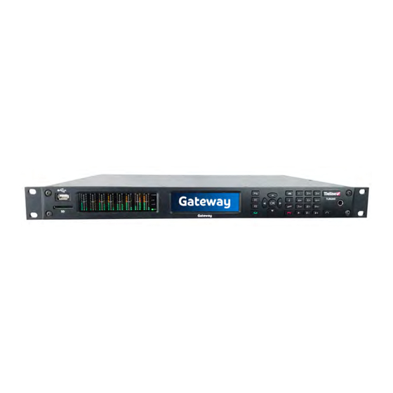
- Page 1 Gateway and Gateway-4 IP Codec User Manual Software Version: 3.02.xx Manual Version: 1.2_20210625 June, 2021...
-
Page 2: Table Of Contents
Part III German Warnings & Safety Information Part IV How to Use this User Manual Part V Glossary of Terms Part VI Overview of Gateway Codec Family Part VII Purchase and Install Channel Licenses Part VIII Gateway 8/16 Front Panel... -
Page 3: Contents
........................... 59 3 Disconnecting a Connection ........................... 61 4 Deleting Programs ........................... 61 5 Lock or Unlock a Program in the Codec ........................... 62 Part XXII Connecting to the ToolBox Web-GUI 1 Opening the HTML5 Web-GUI & Login ........................... 63 2 Security and Changing the Default Password ........................... - Page 4 28 Import and Export Programs ........................... 198 29 Lock or Unlock Programs ........................... 199 30 Configure Country Setting ........................... 200 31 Configuring SNMP in the Codec ........................... 201 32 Download Logs ........................... 203 33 Using the Program Scheduler ........................... 204 34 Configuring Alarms ...........................
- Page 5 Contents Part XXV Installing the Codec at the Studio Part XXVI Reference 1 Regular Maintenance ........................... 279 2 Testing IP Network Connections ........................... 280 3 Compliances and Certifications ........................... 282 4 FCC Compliance Statements ........................... 282 5 Declaration of Conformity ...........................
-
Page 6: Part I Warnings & Safety Information
DO NOT USE Tieline codecs during thunderstorms and lightning. You may suffer an injury using a Tieline codec during a thunderstorm. This can lead to personal injury and in extreme cases may be fatal. Protective devices can be fitted to the line, however, due to the... - Page 7 Supplementary ground connection A supplementary ground terminal is provided on the codec to connect the unit to a ground connection. The ground terminal has an M4 stud with M4 retaining nuts and is compatible with all grounding wires. Remove only NUT 2 to connect your ground wire. The ground wire must have a suitable lug.
- Page 8 Gateway and Gateway 4 Manual v1.2 For North American power connection, select a power supply cord that is UL Listed and CSA Certified 3 - conductor, [18 AWG], terminated in a molded on plug cap rated 125 V, [5 A], with a minimum length of 1.5m [six feet] but no longer than 4.5m. Special Notices for European Users: For European connection, select a power supply cord that is internationally harmonized and marked “<HAR>”, 3 - conductor, 0,75 mm2 minimum mm2 wire, rated 300 V, with a PVC...
- Page 9 Gateway and Gateway 4 Manual v1.2 Translation of previous Chinese safety warning: This unit has two power supplies, please be very careful when using, disconnect two power supplies before maintenance to avoid electric shock. This device must only be used in not-tropical climate regions. This device must only be used at altitude not exceeding 2000 metres.
- Page 10 The product specifications and descriptions within this manual will be subject to improvements and modifications over time without notice, as changes to software and hardware are implemented. Tieline takes no responsibility for any damage to equipment attached to the codec. © Tieline Research Pty. Ltd. 2021...
-
Page 11: Part Ii French Warnings & Safety Information
être installés sur la ligne, cependant, en raison des tensions et des niveaux d'énergie extrêmement élevés associés à la foudre, ces dispositifs peuvent ne pas offrir de protection ni aux utilisateurs ni au codec Tieline, ni aux équipements qui y sont connectés. - Page 12 Connexion à la terre supplémentaire Une borne de terre supplémentaire se trouve sur le codec pour connecter l'appareil à la terre. La borne de terre comporte un goujon M4 avec des écrous de retenue M4 et est compatible avec tous les fils de terre.
- Page 13 Gateway and Gateway 4 Manual v1.2 Mentions spéciales pour les utilisateurs européens : Pour le branchement européen, sélectionnez un cordon d'alimentation harmonisé au niveau international et marqué « <HAR> », 3 - conducteur, fil de 0,75 mm² minimum, calibré pour 300 V, avec une gaine isolée en PVC.
-
Page 14: Part Iii German Warnings & Safety Information
Stromzuleitung kann mit Schutzgeräten versehen werden. Aufgrund der extrem hohen Spannungen und Energien, die bei Blitzschlägen auftreten, bieten diese Geräte jedoch möglicherweise keinen Schutz für die Anwender oder den Tieline-Codec und die an den Codec angeschlossenen Geräte. Es können Sekundärblitze auftreten. Diese Sekundärblitze werden durch Blitzeinschläge hervorgerufen und erzeugen ebenfalls gefährlich hohe Strom- und Energieniveaus. - Page 15 Erdungsanschluss in Ihrem Gebäude an. Zusätzlicher Erdungsanschluss Der Codec verfügt über einen zusätzlichen Erdungsanschluss, um ihn mit einer Erdung zu verbinden. Der Erdungsanschluss verfügt über ein M4-Gewinde mit M4-Haltemuttern und ist mit allen Erdungskabeln kompatibel. Entfernen Sie zum Anschluss des Erdungskabels nur MUTTER 2.
- Page 16 Gateway and Gateway 4 Manual v1.2 Verbindungskabel: Kabel für den Anschluss an die RS232- und Ethernet-Schnittstellen des Geräts müssen UL- zertifizierte Kabel des Typs DP-1 oder DP-2 sein. (Hinweis: bei einer Nicht-LPS-Schaltung) Überstromschutz: Für die Stromversorgung muss die Gebäudeinstallation über ein leicht zugängliches, handelsübliches Zweigstromkreis-Überstromgerät verfügen, das folgenden Spezifikationen entspricht: 1.
-
Page 17: Part Iv How To Use This User Manual
The Gateway has a different front and rear panel to the Gateway 4. A table outlining the differences between the different codec models is placed at the head of sections affected by hardware and/or software differences between the two codec models. -
Page 18: Part V Glossary Of Terms
Destinations An AoIP Destination in the codec is an AES67 stream received by the codec from an AES67 LAN. The Domain Name System (DNS) is used to assign domain names to IP... - Page 19 Gateway and Gateway 4 Manual v1.2 Multi-unicast A multi-unicast program (also known as multiple unicast) can transmit a single audio stream with common connection settings to a number of different destinations. Network Address Translation is a system for forwarding data packets to different private IP network addresses that reside behind a single public IP address.
- Page 20 Gateway and Gateway 4 Manual v1.2 Sources An AoIP source in the codec is an AES67 stream sent by the codec to an AES67 LAN. Secure Sockets Layer is a security protocol for establishing encrypted links between a web server and a browser for online communication...
-
Page 21: Part Vi Overview Of Gateway Codec Family
WANs with MPLS. The Gateway streams up to 16 IP audio channels with support for AES67, ST2110-30, AES3 and analog I/O as standard. The codec can be licensed for between 8 and 16 channels of audio and has two standard versions: · Gateway supporting 8 Channels in/out (8 Mono or 4 Stereo) ·... - Page 22 Gateway and Gateway 4 Manual v1.2 To configure AoIP streaming over AES67 networks, please download the Gateway and Gateway 4 AoIP User Manual from www.tieline.com. Codec Features To view a list of the codec specifications for each codec see: Gateway Specifications · Gateway 4 Specifications ·...
-
Page 23: Part Vii Purchase And Install Channel Licenses
· 8 Channel Upgrade: TLR6200-LIC4ST Contact Tieline or your favorite dealer for pricing and to purchase an upgrade license. To install a license using the codec front panel use the following procedure, or to install using the Toolbox HTML5 Web-GUI see Software License Installation. -
Page 24: Part Viii Gateway 8/16 Front Panel Controls
Operation Button Descriptions Return Button Press to move back through menus & delete characters Function Button 1 Press to activate codec user functions and relays Function Button 2 Press to activate codec user functions Connect Button Press to create an IP connection... - Page 25 Front Panel LED Descriptions LED Description Alarm The ALARM LED flashes red when an alarm is active in the codec. It stops flashing and illuminates solid red after an alarm has been acknowledged. The SIP LED flashes orange when registering to an active SIP server account.
-
Page 26: Part Ix Gateway 8/16 Rear Panel Connections
Safety Information for more details. Dual Redundant AC Power Inputs The codec is powered by dual 90-240 volt, 2A/50-60Hz redundant AC power supplies, which use standard IEC connectors. Shared Analog and AES3 Inputs and Outputs Balanced ANALOG/AES3 IN RJ-45 connectors provide shared stereo analog line inputs 1-4 (analog inputs 1-8), or stereo AES3 digital inputs 1-4 (AES3 inputs 1-8). - Page 27 Gateway and Gateway 4 Manual v1.2 use. If you are only using one Ethernet port, always use LAN1. LED indications allow identification of LAN speeds as follows: · 1000 Mbps: Green = Blinking / Orange = Off · 100 Mbps: Green = Off / Orange = Blinking ·...
-
Page 28: Part X Gateway 4 Front Panel Controls
Operation Button Descriptions Return Button Press to move back through menus & delete characters Function Button 1 Press to activate codec user functions and relays Function Button 2 Press to activate codec user functions Connect Button Press to create an IP connection... - Page 29 Front Panel LED Descriptions LED Description Alarm The ALARM LED flashes red when an alarm is active in the codec. It stops flashing and illuminates solid red after an alarm has been acknowledged. The SIP LED flashes orange when registering to an active SIP server account.
-
Page 30: Part Xi Gateway 4 Rear Panel Connections
Safety Information for more details. Dual Redundant AC Power Inputs The codec is powered by dual 90-240 volt, 2A/50-60Hz redundant AC power supplies, which use standard IEC connectors. Shared Analog and AES3 Inputs and Outputs Balanced ANALOG/AES3 IN RJ-45 connectors provide shared stereo analog line inputs 1-4, or stereo AES3 digital inputs 1-4. - Page 31 Gateway and Gateway 4 Manual v1.2 Dual Gigabit Ethernet Ports Two Gigabit (10/100/1000) RJ-45 Ethernet LAN ports for IP connections. By default, the codec assumes LAN1 is the primary LAN connection and LAN2 is the backup LAN connection when in use.
-
Page 32: Part Xii Menu Navigation
Home screen from any menu. If a complete menu cannot be viewed on a single codec screen, arrows on the right hand side of the screen indicate that the current menu has options below and/or above the visible items. Use the navigation arrows to scroll up and down. - Page 33 Gateway and Gateway 4 Manual v1.2 Home Screen Menus © Tieline Research Pty. Ltd. 2021...
- Page 34 Gateway and Gateway 4 Manual v1.2 Settings Menu Navigation © Tieline Research Pty. Ltd. 2021...
-
Page 35: Part Xiii Input Configuration, Levels And Ppms
Adjusting PPM Meter Reference Scale Settings By default, the PPM METERS on the front of the codec, or in the HTML5 Toolbox Web-GUI, use dBFS to express nominal operating, headroom and noise floor levels. The codec can also automatically adapt to different Tieline reference scales. A Tieline codec with proprietary Tieline session data enabled will automatically adjust the reference level to suit G5 and G3 codecs, or Report-IT. - Page 36 Commander or i-Mix G3 codec. The G3 metering scale is between -29dBFS and 0dBFS and audio levels should average around the nominal 0vu point at -14dBFS. Audio peaks should not exceed 0dBFS.
- Page 37 Gateway and Gateway 4 Manual v1.2 3. Navigate to Reference Level and press the button. 4. Select Report-IT and press The Report-IT metering scale is between -23dBFS and 0dBFS and audio levels should average around the nominal 0vu point at -10dBFS. Audio peaks should not exceed 0dBFS. Adjusting PPM Metering PPM metering options can be adjusted via Settings >...
- Page 38 Gateway and Gateway 4 Manual v1.2 3. Adjustable input settings include: · Input on/off. · Input level: ganging of inputs is not currently supported. · Input Type: Analog (line level input), Digital (AES3 or AES67). · IGC. Polarity/phase inversion · Input Name ·...
- Page 39 +19 dBu (G6 audio scale), +17 dBu (G5 audio scale) and +13dBu (G3 audio scale) to prevent audio clipping. There are three settings; Auto, Fixed and Off. If Auto is configured the codec will detect when incoming audio levels have reduced sufficiently and automatically return input levels to the gain setting prior to IGC being activated.
-
Page 40: Part Xiv Configuring Aes3 Audio
4, or stereo AES3 digital outputs 1-4, plus stereo AES3 digital outputs 5-8. Codecs feature stereo AES inputs and outputs on the rear panel of the codec for AES3 (AES/EBU) format audio. These balanced 110 ohm inputs can operate effectively over distances of up to 100 meters and accept both mono and stereo AES3 signals. - Page 41 The codec implements an Asynchronous Sample Rate Converter (ASRC) to convert the sample rate of an AES3 input to the sample rate set in the codec. The codec sample rate is determined by the selected algorithm. For example, if you select the Music algorithm, the sample rate will be set to 32kHz.
- Page 42 With this setting the codec uses AES3 input sync information to set the codec output sample rate (Note: this is the same as the AES Rx Clock setting in Tieline G3 codecs). The codec initially tries to use the signal on AES inputs 1 and 2 as the clock to which the AES outputs are synchronized. If unavailable, it then attempt to use inputs 3 and 4, or inputs 5 and 6 and so on in that order.
-
Page 43: Part Xv Headphone Output
Gateway and Gateway 4 Manual v1.2 Headphone Output The codec has a 6.35mm (1/4") RTS stereo HEADPHONE output on the front panel. Audio streams and analog inputs or digital inputs can be selected and monitored. Adjust Headphone Output Settings 1. Press the HEADPHONE button to display the headphone monitoring screen. -
Page 44: Part Xvi Inserting Hardware Modules
Do not force a module into the codec. Modules should be installed slowly and gently. 1. Remove power from the codec and then remove the 4 screws from the blanking panel or module installed in the codec. -
Page 45: Part Xvii Ip Streaming, Programs, And Tielink
2. Once the answering codec receives session data it sends an acknowledgment to the dialing codec and streaming can commence. For example, if you configure a stereo program on the dialing codec using Opus encoding at 128kbps with specific jitter settings, this will be configured on the dialing codec when it connects. - Page 46 All of the codecs in your network are secure and cannot be seen by other users unless they have permission to join the network, or a specific codec call-group. See Configuring TieLink Settings for more information.
- Page 47 HTML5 Toolbox Web-GUI, which can be used to configure and edit all program parameters. The following program is configured to send a single stereo audio stream and will allow the codec to both answer and dial if required. A backup Failover dialing connection is configured in case the primary connection fails.
-
Page 48: Part Xviii About Tieserver
TieServer Domain with TieLink or the TieServer Console. If you already have Report-IT Enterprise or the Cloud Codec Controller, the same domain can be used for TieLink. Following is a diagram showing the relationship between a TieServer Domain and Tieline's software products; TieLink, the TieServer Console, and the Cloud Codec Controller. -
Page 49: Part Xix Configure Language And Country
Important Note: The country setting affects whether G.711 µ-Law (North America/Japan) or A-Law (Europe/Australasia) coding is used over IP and SIP connections. Configure Language Setting The codec menus are available in English, French, Spanish and Portuguese. To configure the language setting in the codec: 1. Press the SETTINGS button. -
Page 50: Part Xx About Sip
The benefit of using a SIP server to connect is that any device can be ‘discovered’ via its SIP server registration. This is particularly useful if a codec is being used in multiple locations with IP addresses that are DHCP assigned. These DHCP addresses are unreliable and are not recommended for live broadcast connections. - Page 51 1. Register the codec to a SIP server using SIP account credentials. 2. Configure a SIP interface in the codec. Note: This SIP1 or SIP2 interface will include the proxy and port settings, as well as the selected IP interface used to make the connection, e.g.
-
Page 52: Configuring Sip Interfaces
· Failover and SmartStream PLUS redundant streaming are not available with SIP connections. · When connecting to a Tieline G3 codec using SIP you need to manually select the G3 audio reference level in the codec. To do this select SETTINGS >... - Page 53 SIP from behind a firewall. Enter the public IP address and then configure port forwarding to route traffic to the codec's local IP address behind your firewall. Note: Do not enter a Public IP address if STUN is configured.
-
Page 54: Configuring Sip Accounts
Up to 16 SIP accounts can be configured and registering codecs for SIP connectivity is simple. First, select the SIP server to which the codec will be registered. On a LAN this may be your own server, or it could be one of the many internet servers available. When registering an account with a SIP server you will be provided with: ·... - Page 55 Gateway and Gateway 4 Manual v1.2 3. Select an account which is Not Registered and press 4. Select Edit and then press to individually select and enter SIP server account details. 5. Navigate to each field in turn and press the button to enter SIP account credentials.
- Page 56 Registered is displayed when an account is registered to a SIP server. The SIP LED on the front panel of the codec also displays the following SIP account registration states: USER (SIP) LED State Description Not Illuminated Indicates an account is not yet registered.
-
Page 57: Part Xxi Connecting Quickly
Before creating a new IP connection adjust the following: 1. Attach power to the codec. 2. Attach an RJ45 Ethernet cable to one of the LAN ports on the codec's rear panel. 3. Attach headphones to the 6.35mm (1/4") headphone jack on the codec's front panel. - Page 58 Edit the IP Address in a Loaded Program It is not possible to create a program from the codec front panel, however it is possible to edit an IP address for each audio stream connection. Important Note: The IP address for an audio stream connection can only be edited when it is disconnected.
-
Page 59: Monitoring Connections
21.2 Load and Dial Custom Programs Custom programs stored on the codec are simple to load and dial from the codec front panel. 1. Press the HOME button to return to the Home screen. 2. Use the navigation buttons to select Programs and press the button. - Page 60 Gateway and Gateway 4 Manual v1.2 4. Navigate to the Connections screen and press the CONNECT button to make a connection. 5. A dialog appears during the connection process with connection details displayed. Editing the IP Address or ISDN Number It is possible to edit the IP address of a destination or the ISDN number for ISDN calls.
-
Page 61: Disconnecting A Connection
Gateway and Gateway 4 Manual v1.2 Disconnecting a Connection 21.3 1. Navigate to the Connections screen and select a connection, then press the red DISCONNECT button on the numeric KEYPAD at any time to hangup an individual connection. 2. Use the right navigation button to select Disconnect and press the button to confirm the disconnection. -
Page 62: Lock Or Unlock A Program In The Codec
It is essential to lock multi-stream programs in a codec or they will be unloaded by the first call received. Only mono and stereo connections can be answered when the Lock Program feature is disabled. -
Page 63: Part Xxii Connecting To The Toolbox Web-Gui
3. Ensure the PC used to configure the codec is connected to the same LAN. 4. Launch a web browser and type the IP address of the codec into the address bar of the browser, e.g. http://192.168.0.xxx (the last digits are the private address details unique to your codec over a private LAN). - Page 64 Using the Web-GUI over the Internet If the codec is connected to the internet and is assigned a public static IP address it is possible to connect and configure it from any PC connected to the internet. If multiple browsers are open on a PC for different codecs it is possible to customize the browser title for simple identification.
-
Page 65: Security And Changing The Default Password
Configure SIP Allow and Block lists for more information. 5. An SSL security certificate can be installed on each codec in your network to ensure it is a trusted device within your network. See Installing a Security Certificate for more information. - Page 66 Toolbox HTML5 Web-GUI Login Dialog on a Merlin Codec Creating a New Password The authentication login password can be changed at any time using the codec keypad and LCD SCREEN. Note that passwords are case sensitive: 1. Press the SETTINGS button.
-
Page 67: Web-Gui
The following sections provide an overview of the different configuration panels available within the codec's HTML5 Toolbox Web-GUI. Navigate with the mouse pointer to the Menu bar at the top of the Web-GUI screen and click to select and open each panel in turn. - Page 68 Gateway and Gateway 4 Manual v1.2 Adjusting the Theme To adjust the Theme or 'skin' of the HTML5 Toolbox Web-GUI, navigate to the Menu bar at the top of the screen and click Settings, then click to select the preferred option. Note: this manual uses the White theme for most images.
- Page 69 Gateway and Gateway 4 Manual v1.2 Connect Panels: Load & Connect Programs & Manage Audio Streams Connections Panel Feature Description Program Connect Click to connect or disconnect all audio streams in a program. Disconnect buttons Connect / Disconnect Click the Connect/Disconnect button to connect/disconnect button and Connection all connections in an audio stream.
- Page 70 Contact List Feature Description Codec Name The name given to a codec to identify it when a program is created Stream Name The name given to a stream to identify it when a program is created Status Displays the status of an audio stream, which can be Available,...
- Page 71 Gateway and Gateway 4 Manual v1.2 Feature Description Program list The list of saved programs in the codec Create New Program Click to create a new program using the program wizard. button Delete Selected Click to delete all selected programs...
- Page 72 Gateway and Gateway 4 Manual v1.2 Statistics Panel Feature Description Expand/Collapse Click to show/hide audio stream statistics, including packet arrival data info. New Chart button Click the New Chart button to select a Data Series and create a customized Statistics panel. Scheduler Panel Feature Description...
- Page 73 1 Grouping Drag and drop a column header to group event history by that column, e.g. Codec Time. 2 Event History List View the codec's history of scheduled events. 3 Purge Scheduler Click to clear all event history displayed. History button 4 Close button Click to close the panel.
- Page 74 Gateway and Gateway 4 Manual v1.2 Audio Menu Panels Important Note: Tieline codecs have different input/output configurations, therefore the images shown in this section may not reflect the number of inputs displayed in your codec Web-GUI. Audio Options Feature Description...
- Page 75 Gateway and Gateway 4 Manual v1.2 Inputs Panel Feature Description Settings button Click to adjust input Name, Type, Polarity Inverted and IGC settings EQ button Click to enable and adjust 10 band EQ settings for individual inputs Compressor button Click to enable the input compressor on each input On/Off button Click to toggle an input on or off Input Sliders/Faders...
- Page 76 Gateway and Gateway 4 Manual v1.2 Matrix Editor Panel Feature Description Matrix Editor crosspoint Click to select and deselect audio crosspoints to customize matrix routing. Change Mix Click to select the default or Custom matrix mix to view and edit. Options include Load, Delete and Rename a mix Save Click to save changes to a custom matrix mix Save as...
- Page 77 Dig.Output Type > [select AoIP or AES3]. Send/Return slider Use the Send/Return slider to adjust the balance between the mix of incoming (return/decoder) audio and outgoing (send/input) audio fed to each codec output Output PPM meter Output PPM meter Send/Return indications...
- Page 78 Close button Click to close the panel. Important Note: Codec front panel PPMs 1-6 and PPMs in the PPMs panel always reflect the default program settings and do not display customized mix adjustments using Matrix Editor.
- Page 79 Gateway and Gateway 4 Manual v1.2 Media Menu File Manager Feature Description Folder and File View View all folders and files on an external drive / removable media New Folder Select the drive or a folder and then click to create a new sub-folder Upload Click to select and upload a new file onto removable...
- Page 80 Use the connected state of the Click to configure a relay to toggle based on connection codec to toggle a local output status. Back / Add New Rule button Click to add a new rule, or exit the rule creation function.
- Page 81 Gateway and Gateway 4 Manual v1.2 Alarms Panels: Configure & Monitor Alarms Configure Alarms Panel Feature Description 1 List of alarm types Click to select an alarm type to configure. 2 Enable Alarm check-box Click the Enabled check-box to enable the currently selected alarm.
- Page 82 Gateway and Gateway 4 Manual v1.2 Alarm Dissemination Panel Alerts for each alarm severity level are configured using the Alarm Dissemination panel. Feature Description 1 List of alarm severity levels Click to select an alarm severity level to configure it. 2 Front panel alarm...
- Page 83 Gateway and Gateway 4 Manual v1.2 Current Alarms Feature Description 1 Current alarm description View a list of active alarms in the codec 2 Close button Click to close the panel 3 Acknowledge selected alarm Click to acknowledge a selected alarm.
- Page 84 Gateway and Gateway 4 Manual v1.2 Transport Panels There are several Transport panels which can be opened in the Web- GUI. Each panel provides specific transport-related configuration settings and options. Click to select and open each panel. As an example, the Network panel is displayed with network interface configuration options. A brief description of the other panels is also provided.
- Page 85 Settings panels Feature Description 1 Date and Time Click to open the panel view and sync the codec to NTP time. 2 Firmware tab Click to open the panel; view software versions, download firmware and perform an upgrade. 3 Licensing tab Click to open the panel;...
- Page 86 Lock Loaded User Program check-box to lock the currently loaded program in the codec; enable and assign a hostname to the codec to provide a flexible way of identifying the codec on a network; configure IP audio data packets for expedited or assured forwarding (Quality of Service or QoS) when traversing different networks.
- Page 87 About Panel Details in this panel displayed include the Toolbox and firmware version, as well as the codec serial number. Note: The codec name displayed varies as per how many channels are enabled in the codec. E.g. An 8 channel codec will display Gateway 8. The following image confirms this is a 16 channel I/O unit named Gateway 16.
-
Page 88: Configure Programs With The Connections Panel
Gateway Programs Supports program connections using up to 16 channels of audio, 8/16 depending on codec configuration purchased (between 8 and 16 channels available for purchase) The Connections panel allows: · The configuration of new programs. · Editing of existing programs. - Page 89 Gateway and Gateway 4 Manual v1.2 2. Select Default Templates and then click the drop-down arrow to select one of the supported default templates in the codec. Note: Default templates available vary depending on the codec purchased, e.g. Gateway 4, Gateway 8, and Gateway 16.
- Page 90 Gateway and Gateway 4 Manual v1.2 5. To configure new connection settings, or edit existing connection settings, click the Edit symbol 6. The Edit symbol expands each audio stream and dialing and answering connection to reveal configuration settings. Hover over the Information symbol to view details of each configuration setting.
- Page 91 Gateway and Gateway 4 Manual v1.2 8. Click the right-facing arrows to expand stream settings. Click the down-facing arrows collapse expanded stream settings. Audio stream connections can be connected, disconnected and managed from within the Connections panel. 9. Click the Connect/Disconnect symbol for an active connection and then click the drop- down Bit Rate arrow to select and renegotiate a new bit-rate.
- Page 92 Gateway and Gateway 4 Manual v1.2 Important Notes: · Renegotiation will result in a temporary loss of audio. · It is not possible to renegotiate the connection bit rate of a SIP connection. 10. To disconnect an individual connection, click the Connect/Disconnect symbol for an active connection.
-
Page 93: Using The Html5 Toolbox Quick Connect Web-Gui
The HTML5 Quick Connect Web-GUI is designed for simple peer-to-peer connections and non- technical users. It has a reduced feature-set and allows users to: 1. Load existing programs in a codec via the Program Loader panel and then dial via the Quick Connect panel. - Page 94 Gateway and Gateway 4 Manual v1.2 2. The Check-box symbol appears next to the program name to confirm it has been loaded and the Load button changes to an Unload button. To unload a program click the Unload button. Dial a Loaded Program 1.
- Page 95 Gateway and Gateway 4 Manual v1.2 Disconnect a Loaded Program 1. Click the Disconnect button in the Quick Connect panel. 2. Click Yes in the confirmation dialog to disconnect the connection. Dial Peer-to-Peer over IP with Quick Connect Important Notes: ·...
-
Page 96: Configuring Ip Settings
3. Click the select the appropriate Sample Rate and Bit Rate for the connection. Note: If only one sample rate is available this will be automatically selected. 4. Click in the Destination text box and enter the IP address of the destination codec, or click the Address Book button to select a preconfigured TieLink contact. - Page 97 If you want to dial a codec with a public IP address you simply dial the IP address to connect. If you want to dial a codec with a private IP address you need to perform network address translation (NAT).
- Page 98 2. Click Save to store the new setting. IPv4 Address Configuration Click to select the TCP/IP tab in the Network panel to configure settings. The codec is capable of automatic DHCP address assignment, or manually configured static IPv4 address configuration via the Configure IPv4 drop-down menu.
- Page 99 1. Automatically: An address is automatically assigned to the codec when you connect the codec to an IPv6 router. This process is similar to how an IPv4 DHCP address is assigned. 2. Manually: Select to enter static IPv6 address details.
- Page 100 2. Click Save to store all configuration settings. Manual IPv6 Address Assignment 1. To configure IPv6 address details into the codec manually, select Manually and enter details into the Address, Prefix and Gateway text boxes. 2. Click Save to store all configuration settings.
- Page 101 However, the actual primary interface used at each location can vary for each codec. For one codec it may be an Ethernet interface and for another it may be a Wi-Fi connection. This allows you to configure site-specific settings to suit the available network interfaces at different remote locations.
- Page 102 Gateway and Gateway 4 Manual v1.2 Configure Cross-Site Request Forgery CSRF (Cross-Site Request Forgery) protection can be configured to protect the codec from CSRF attacks. To enable or disable this setting: 1. Open the HTML5 Toolbox Web-GUI and click Settings at the top of the screen, then click Options to display the Options panel.
-
Page 103: Enabling The Cloud Codec Controller
3. Click Save to store the new configuration. Important Notes: · Ensure CSRF is disabled in the codec or it will not be able to connect to the CCC. This setting is [OFF] by default and is also available in the codec menu via Settings >... - Page 104 Gateway and Gateway 4 Manual v1.2 3. Click the Fuse-IP Mode drop-down menu and select Server if the codec is not initiating the connection. 4. Leave the default Fuse-IP Port as 8999 in most situations unless this port is already in use, e.g.
- Page 105 Note: the studio codec should be configured in server mode. 4. Enter the Fuse-IP Server Address, which is the public static IP address of the server codec at the studio. Then enter the server codec's serial number in the Server Serial Number text box.
- Page 106 Fuse-IP On. Important Notes: · Data is sent by the codec over the newly created 'tunnel' as soon as Fuse-IP is enabled, even if a connection has not been configured and dialed. Depending on the number of interfaces being used, the codecs may transmit and receive up to 24MB of data per hour at each end of the link.
-
Page 107: Line Hunt Call Answering
For the next eight audio streams, select Group 2 to route outgoing and incoming calls via inputs and outputs 9 to 16. These inputs and outputs on the codec can be routed to a different studio or station. -
Page 108: Configuring Input Settings
Gateway and Gateway 4 Manual v1.2 Any Tieline G5 codec dialing can display a designated Caller ID in the Connection panel. In the following example, Remote1 has called into the codec using a specific caller ID, which is displayed next to the Send and Return link quality connection. - Page 109 Configuring Input Settings Selecting Analog and Digital Audio Sources Codec inputs can be configured for AES3, AES67 or analog line level audio sources. Use the Audio Options panel in the HTML5 Toolbox web-GUI to configure digital inputs globally for © Tieline Research Pty. Ltd. 2021...
- Page 110 AES3 or AES67 AoIP input sources. See Input Configuration, Levels and PPMs for more details. After setting the Digital Input Type in the Options panel, configure the codec for either analog or digital input types using the Inputs panel as follows. 1. Click the Input Settings symbol.
- Page 111 Gateway and Gateway 4 Manual v1.2 3. Click Save to store the new setting. Renaming Inputs 1. Select the Input Settings symbol on the input being renamed. 2. Click in the Name text box to enter a new name, or edit an existing name. 3.
- Page 112 Gateway and Gateway 4 Manual v1.2 4. Click Save as preset to save an EQ preset, e.g. for a particular announcer. Click View presets to recall a previously stored EQ preset. 5. Click Back to view all inputs. Adjust Compression Settings To to enable and adjust input compression settings.
- Page 113 Save. Audio Reference Levels By default, the PPM METERS on the front of the codec, or in the HTML5 Toolbox Web-GUI, use dBFS to express nominal operating, headroom and noise floor levels. The codec can also automatically adapt to different Tieline reference scales. A Tieline codec with proprietary Tieline session data enabled will automatically adjust the reference level to suit G5 and G3 codecs, or Report-IT.
-
Page 114: Configuring Output Settings
Inputs 1-8 can be configured as analog or digital inputs (AES3 or 8/16 AES67) in pairs Gateway Web-GUI 8 - 16 Outputs and PPMs displayed (depending on codec 8/16 Outputs panel configuration purchased) The Outputs panel can be configured to support either analog or digital output types for outputs 1 to 4 (Gateway 4) or outputs 1 to 8 (Gateway 8/16). - Page 115 Gateway and Gateway 4 Manual v1.2 Select Output Type as Analog or Digital To select either analog or digital output types for outputs 1 to 8 (in pairs): 1. Open the HTML5 Toolbox Web-GUI and click Audio in the Menu Bar, then click Outputs to display the Outputs panel.
-
Page 116: Monitoring Ppms
PPMs Panel decoders simultaneously Gateway PPM Meters Gateway 8 has 8 PPMs on codec front panel capable of 8/16 monitoring 8 inputs, 8 outputs, 8 encoders or 8 decoders; Gateway 16 capable of monitoring 16 inputs, 16 outputs, 16 encoders or 16 decoders... - Page 117 Gateway and Gateway 4 Manual v1.2 The PPMs panel is able to monitor incoming and outgoing audio streams in the codec. PPMs grouped by stream and identified by Stream Name Click the drop-down PPM selector arrow to select whether the panel will display PPMs for: ·...
- Page 118 Toolbox HTML5 Web-GUI and the AES67 Web-GUI. For more details please download the AoIP User Manual. Toolbox AES67 Destinations panel displaying incoming codec audio Toolbox AES67 Sources panel displaying outgoing codec audio Important Note: PPMs on the AoIP Destinations panel are inactive if the Digital Input Type is not set to AES67 and the corresponding input Type is not set as Digital.
-
Page 119: Configure Dial And Answer Programs
TieLink. Note: The following instructions will display how to configure a dial and answer program, with a backup connection and file playback. If the codec will either dial or answer only, select the option and the wizard will automatically display relevant screens to allow you to configure the codec correctly. - Page 120 Some Programs displayed in the Gateway-16 Configuring a Mono or Stereo Peer-to-Peer Program: Dialing Important Notes: Before configuring a program please note: · A program cannot be edited in the Program Manager when loaded in the codec. · Lock a loaded custom program or multistream program in a codec to ensure it cannot be unloaded by a codec dialing in with a different program type.
- Page 121 Creating Rules. 4. Enter a Stream Name, then add a Caller ID and configure the codec to dial, answer or dial and answer. Then click Next. Note: The caller ID is used to identify calls. Select Advertise On TieLink if configuring answering audio streams that will be used as dialing destinations in TieLink Traversal Server Contact Lists.
- Page 122 3. Channel 2: The answering codec will always route incoming calls to codec Channel 2 (right output). 5. This audio stream connection in the wizard will allow the codec to dial. Enter the name of the connection in the text box, then click Next.
- Page 123 LAN2). Note: By default Any will select LAN1 if it is available and LAN2 if it is unavailable. Important Note: The Remote Audio Port is the codec port at the remote end of the link to which you are sending audio. The Local Audio Port is used by the local codec to receive audio from the remote codec.
- Page 124 This will increase the likelihood that the FEC packets will take an alternate route to the primary stream's packets. This means that if primary audio stream packets are not received at the remote codec, there is a good chance © Tieline Research Pty. Ltd. 2021...
- Page 125 LAN2. The redundant stream uses Remote Audio Port 9001 by default and the Local Audio Port allocated is Automatic. Note: Automatic indicates that the codec will arbitrarily allocate the local port value and send this information to the codec to which you are dialing.
- Page 126 Important Note: When Auto Reconnect is enabled, the dialing codec will continue to attempt a connection with the remote codec until Disconnect is pressed either on the dialing codec's keypad, or in the Web-GUI. To configure a backup connection: 1.
- Page 127 Gateway and Gateway 4 Manual v1.2 Important Note: When Failover is enabled, the codec will fail over to a backup connection under the following circumstances: · There is sudden loss of connectivity to the primary destination. · The remote codec disconnects the primary connection.
- Page 128 The codec is capable of being configured to accept calls via different transports (e.g. IP and ISDN), or to accept calls using different audio ports. If you are configuring the codec to allow it to answer one or more incoming audio stream connections: 1.
- Page 129 Output Audio Source options include: · Connection: Decoded connection audio sent from a remote codec (Note: this must be selected as one of the configured sources). · Input: Input audio looped to the physical codec outputs.
- Page 130 · USB backup audio is only sent to the outputs of the local codec to which a USB stick is attached. USB file audio is not sent to encoders and cannot be transmitted via an audio stream to another codec.
- Page 131 Connections panel and the Program Loader panel (in the Quick Connect web-GUI). Select and connect audio streams in a program using the Connections panel, or connect the program manually using the codec front panel. © Tieline Research Pty. Ltd. 2021...
-
Page 132: Configure Phase Locked Surround Programs
Gateway 16 displays program types that support 16 panel channels in/out. The codec is capable of streaming multichannel phase-locked surround sound audio streams according to SMPTE ST 2110-30 standards. Support is available for streaming 4, 6 and 8 digital channels in phase-locked mode. - Page 133 8.0, and 5.1 or 6.0, for streaming is determined when selecting the encoding algorithm when creating a program. Codec Model Note: Only 4.0 channel phase-locked audio is supported in the Gateway 4. 5.1 Channel Mapping for 5.1 and 7.1 Phase-Locked Surround Streams Encoder/Decoder 1 x 5.1 Channel Program...
-
Page 134: Default Program Ports
To view other important ports that need opening for SIP, Fuse-IP, Web-GUI use and G3 Toolbox software, please see Installing the Codec at the Studio in this user manual. -
Page 135: Configure Multi-Unicast Dialing Programs
· cannot be unloaded by a codec dialing in with a different type of program. For example, if a multistream program is not locked it will be unloaded by a mono or stereo call. - Page 136 · FEC is not available for multi-unicast connections. · If a codec is answering more than one mono or stereo multi-unicast connection it is necessary to create an answering program to suit the answering configuration and lock this program in the codec.
- Page 137 Gateway and Gateway 4 Manual v1.2 Important Notes for Rules: · The Gateway 4 codec has 8 hardware GPIOs and 56 logical outputs, and the Gateway 8/16 has 16 hardware GPIOs and 48 logical outputs; both codecs also have 3 virtual inputs, and 64 WheatNet Logic Inputs/Outputs.
- Page 138 3. Channel 2: The answering codec will always route incoming calls to codec Channel 2 (right output). 5. This audio stream connection in the wizard will allow the codec to dial. Enter the name of the connection in the text box, then click Next.
- Page 139 LAN2). Note: By default Any will select LAN1 if it is available and LAN2 if it is unavailable. Important Note: The Remote Audio Port is the codec port at the remote end of the link to which you are sending audio. The Local Audio Port is used by the local codec to receive audio from the remote codec.
- Page 140 LAN2. The redundant stream uses Remote Audio Port 9001 by default and the Local Audio Port allocated is Automatic. Note: Automatic indicates that the codec will arbitrarily allocate the local port value and send this information to the codec to which you are dialing.
- Page 141 Gateway and Gateway 4 Manual v1.2 Important Notes: · SmartStream PLUS redundant streaming over multiple IP interfaces mitigates lost packets and provides IP network backup if an IP link is lost. · Only one SmartStream PLUS connection per audio stream is supported with uncompressed PCM, or when encoding with aptX Enhanced, G.711 or G.722 algorithms.
- Page 142 Output Audio Source options include: · Connection: Decoded connection audio sent from a remote codec (Note: this must be selected as one of the configured sources). · Input: Input audio looped to the physical codec outputs.
- Page 143 · Backup file audio is only sent to the outputs of the local codec. File playback audio is not sent to encoders and cannot be transmitted via an audio stream to another codec.
- Page 144 5. The newly created program can be loaded from within the Program Manager panel and Connections panel. Select and connect audio streams in a program using the Connections panel, or connect the program manually using the codec front panel. © Tieline Research Pty. Ltd. 2021...
-
Page 145: Configure Multicast Server Programs
Gateway 8, and up to 16 different multicast server and/or client streams in Gateway 16 In multicast server mode a 16 channel Gateway codec supports sending 1, 2, 3, 4, 6, 8 or 16 multicast audio streams to unlimited endpoints over compatible IP networks. It is also possible to use multicast client mode to simultaneously receive up to 16 separate multicast streams. - Page 146 · Relay functionality is available for multicast connections between Tieline codecs. · It is not possible to connect to a G3 codec and receive multicast IP audio streams. 1. Open the HTML5 Toolbox Web-GUI and click Connect in the Menu Bar, then select Program Manager to launch the Program Manager panel.
- Page 147 Gateway and Gateway 4 Manual v1.2 · If you want to use an existing program as a template, select this option. Then click Next. Important Notes: When you decide to use an existing program as a template, the new program inherits all the settings of the template program and you can adjust these settings as required by continuing through the program wizard.
- Page 148 Rules. 4. Enter the Stream Name, then click Next. 5. This audio stream connection in the wizard will allow the codec to dial. Enter the name of the connection in the text box, then click Next. 6. Configure the transport settings for the connection, then click Next. Note: select UDP/IP +RTP for RFC compliant streaming.
- Page 149 FEC packets will take an alternate route to the primary stream's packets. This means that if primary audio stream packets are not received at the remote codec, there is a good chance that FEC packets taking an alternate route will be received and replace them.
- Page 150 13. After configuring all streams in the multicast server program click Save to store the program settings, then click Finish. Important Notes: There is no jitter buffer setting on the server codec because it never receives audio packets. 14. Configure multicast server and...
-
Page 151: Configure Multicast Client Programs
· Use firmware higher than 2.8.xx in the Bridge-IT, Genie and Merlin families of codecs to enable auxiliary data. · It is not possible to connect to a G3 codec and receive multicast IP audio streams. · To copy multicast client programs onto multiple codecs see Backup and Restore Functions. - Page 152 Important Notes for Rules: · The Gateway 4 codec has 8 hardware GPIOs and 56 logical outputs, and the Gateway 8/16 has 16 hardware GPIOs and 48 logical outputs; both codecs also have 3 virtual inputs, and 64 WheatNet Logic Inputs/Outputs. (WheatNet logic I/Os allow Tieline WheatNet-IP enabled codecs to activate functions across a WheatNet-IP network.
- Page 153 Gateway and Gateway 4 Manual v1.2 4. Enter the Stream Name, then click Next. 5. This audio stream connection in the wizard will allow the codec to dial. Enter the name of the connection in the text box, then click Next.
- Page 154 When configuration is complete click Next. Important Notes: Automatic or fixed jitter buffer settings can be adjusted on individual client codecs as required. There is no jitter buffer setting on the server codec because it never receives audio packets.
- Page 155 · Backup file audio is only sent to the outputs of the local codec. File playback audio is not sent to encoders and cannot be transmitted via an audio stream to another codec.
- Page 156 · File playback will occur automatically if the silence threshold parameters are breached; if the codec is not connected for any reason file playback will commence. To stop file playback open the Connections panel in the HTML5 Web-GUI, click to select the file playback connection, then click Disconnect.
-
Page 157: Multicast Server And Client Programs
Simply select the program to support both server and client capability and configure the program as per the previous instructions in this user manual. Note: the number of streams supported will vary depending on the model of codec. © Tieline Research Pty. Ltd. 2021... -
Page 158: Configuring Sip
1. Register the codec to a SIP server using SIP account credentials. 2. Configure a SIP interface in the codec. Note: This SIP1 or SIP2 interface will include the proxy and port settings, as well as the selected IP interface used to make the connection, e.g. - Page 159 7. Enter a public IP address in the Public IP text box if you want to dial over SIP from behind a firewall. Then configure port forwarding to route traffic to the codec's local IP address behind your firewall. Note: Do not enter a Public IP address if STUN is configured.
- Page 160 Up to 16 SIP accounts can be configured in the codec and registering codecs for SIP connectivity is simple. First, select the SIP server to which you will register your codec. On a LAN this may be your own server, or it could be one of the many internet servers available. We recommend that you use your own SIP server and configure it to use G.711, G.722, MP2 and AAC algorithms.
- Page 161 4. Click the Enable check-box at the top of the panel and then click the Save button to register the codec to the server. 5. If an account is registered successfully, the account registration indicator changes from red to green, and Not Registered (above the Enable check-box) becomes Registered.
- Page 162 Gateway and Gateway 4 Manual v1.2 6. In the Toolbox Web-GUI the red SIP indicator adjacent to the codec Online indicator also changes to green when an account is currently registered in the codec and ready to be used when dialing over SIP.
- Page 163 The SIP Filter Lists panel allows filtering of SIP URIs and User Agents to provide greater security for your codec connections. For example, add trusted network codecs to the URI Allow List in this panel and only codecs using these SIP URIs will be able to connect. This is like saying, "if you have the key you can open the door"...
-
Page 164: Configure Peer-To-Peer Sip Programs
23.18 Configure Peer-to-Peer SIP Programs SIP programs are very similar to how a normal Tieline IP program is configured. The codec supports dialing over SIP using a registered SIP server account, or peer-to-peer using one of the two SIP interfaces SIP1 and SIP 2. It is also necessary to select SIP as the Session Protocol. - Page 165 · For more details about rules see Creating Rules. 4. Enter the Stream Name and configure the codec to dial, answer or dial and answer. Then click Next. Note: The following example will display how to configure a dial and answer program. If you want the codec to either dial or answer only, select the option and the wizard will automatically display screens to allow you to configure the codec correctly.
- Page 166 TieLink, and G3 profile or G3 channel information can not be used for SIP connections because Tieline session data is replaced by SDP for SIP connections. 5. This audio stream connection in the wizard will allow the codec to dial. Enter the name of the connection in the text box, then click Next.
- Page 167 · The default UDP audio port when using SIP for a peer-to-peer connection is 5004 in Tieline codecs. To contact a codec that is behind a firewall or NAT-enabled router, it is essential that this and all other relevant ports are open and forwarded to the other device.
- Page 168 Gateway and Gateway 4 Manual v1.2 10. Click Add a remote jitter preference to send preferred jitter settings to a remote codec. Note: this is just a preference as per EBU Tech 3368 and there is no guarantee that the remote codec will accept or support these jitter configuration settings.
- Page 169 4 backup audio sources to maintain program audio at transmitter sites. Output Audio Source options include: · Connection: Decoded connection audio sent from a remote codec (Note: this must be selected as one of the configured sources). · Input: Input audio looped to the physical codec outputs.
- Page 170 · USB backup audio is only sent to the outputs of the local codec to which a USB stick is attached. USB file audio is not sent to encoders and cannot be transmitted via an audio stream to another codec.
- Page 171 Gateway and Gateway 4 Manual v1.2 · The USB stick can be inserted or removed at any time as long as the codec is not already playing audio in failover mode. Removing the USB stick while audio is playing from it will result in poor audio quality and should be avoided. If it is removed accidentally you must reboot the codec to ensure USB failover will work reliably in future.
-
Page 172: Answering Multiple Sip Peer-To-Peer Calls
SIP account you have registered to the codec. In this way, when a call is received via a particular account, the call is routed to the audio stream with the matching audio answer route. This process also reliably predetermines which inputs and outputs are used on the answering codec (e.g. -
Page 173: Load, Unload And Dial A Program
For example, if a multistream program is not locked it will be unloaded by a mono or stereo call. - Page 174 3. If Lock Loaded User Program has been configured in the Options panel, a black Padlock symbol appears next to the program name in the Connections panel, to indicate a program is locked in the codec. Unload a Program 1. To unload a loaded program click Change Program.
- Page 175 Gateway and Gateway 4 Manual v1.2 3. Click the connection Connect/Disconnect symbol and then click Connect; this connects an individual audio stream connection. Disconnecting a Program To disconnect audio streams and connections within an existing program there are three options: 1.
- Page 176 Gateway and Gateway 4 Manual v1.2 Change Dialing Settings To edit destination dialing settings: 1. Click the Edit symbol adjacent to a connection. Note: The connection must be disconnected before editing. 2. Adjust dialing and connection settings and then click Save to change edited settings in the program.
-
Page 177: Configure Speed Dialing
Gateway and Gateway 4 Manual v1.2 Configure Speed Dialing 23.21 The Toolbox HTML5 web-GUI supports dialing programs using preconfigured speed dials. This is configured and managed using the Speed Dial panel. Create a New Speed Dial To configure speed dialing: click 1. -
Page 178: Delete A Program
Gateway and Gateway 4 Manual v1.2 5. Click Save to store all edited speed dials. Important Note: To view speed dial configurations using the front panel of the codec select SETTINGS > Speed Dial and press the button. 23.22 Delete a Program 1. -
Page 179: Matrix Editing
Open the HTML5 Toolbox Web-GUI and click Audio in the Menu Bar, then click Matrix Editor to open the Matrix Editor panel. In the following image the default stereo matrix for the Gateway 8 is loaded, as indicated at the top of the panel. The Gateway 4 codec will only display 4 inputs and outputs only. - Page 180 · The number of channels available in the Matrix Editor depends on how many channels are licensed. This can vary between 8 and 16 channels for a Gateway codec. Using the Matrix Editor Routing can be adjusted very simply in the Matrix Editor. To edit default matrix settings click a crosspoint to select or deselect it.
- Page 181 2. Enter a new Name and Description (if required) and click Save. 3. The new custom mix stays loaded in the codec until a new mix is loaded, an incompatible program is loaded, or program defaults are restored via Reset Defaults.
- Page 182 Gateway and Gateway 4 Manual v1.2 Important Notes: · If a new program is loaded and it is compatible with the current custom mix then it will remain loaded. If an incompatible program type is loaded, the last compatible mix to suit the new program type is loaded, including any previous runtime changes.
- Page 183 Gateway and Gateway 4 Manual v1.2 © Tieline Research Pty. Ltd. 2021...
-
Page 184: Adjusting The Connection Bit Rate
Gateway and Gateway 4 Manual v1.2 Adjusting the Connection Bit Rate 23.24 1. Open the HTML5 Toolbox Web-GUI and click Connect, then select Connections to open the Connections panel. 2. Click the Connect/Disconnect symbol for an active connection and then click the drop- down Bit Rate arrow to select and renegotiate a new bit-rate. -
Page 185: Configuring Isdn
Configuring ISDN 23.25 A single module slot is available to insert an optional Euro ISDN module into the codec for primary or backup connections. The Basic Rate Interface (BRI) of ISDN consists of 2 bearer (B) channels at 64 kbps each and 1 data (D) channel at 16 kbps, i.e. (2B +D). This is provided over a 2 wire facility and the two B channels can be bonded together to form a single 128kbps channel. - Page 186 23.25.1 Configuring ISDN Modules ISDN settings in the Modules panel determine how each codec module operates at a particular site. A user may copy similar programs between codecs installed at different locations and also configure site-specific settings for how each ISDN module should connect. ISDN module settings may need to be adjusted depending on country and network requirements.
- Page 187 However, if a DN or MSN number is not entered in the codec and multiple B channels are available, the codec may use any channel to answer an incoming call. To ensure calls are routed consistently, enter a DN/MSN number...
- Page 188 Typically, each ISDN BRI service in the US will have two SPIDs and these must be entered correctly. When you enter a SPID into your codec and connect it to an ISDN line, an initialization and identification process takes place, whereby the terminating equipment (your codec) sends the SPID to the switch.
- Page 189 · Expected dialing behaviors, e.g. if B channels should bond or not, and whether audio streams need to use Dial and Answer Route tags. · The type of call being received by the codec, e.g. Tieline (with Tieline Session Data) versus non-Tieline sessionless calls.
- Page 190 Bonding Setting Behavior Bonded Unbonded (May Calls using the same algorithm from the same Tieline codec, Bond) or sessionless calls, will attempt to bond when received. Calls using incompatible algorithms will not be bonded Bonded Only Will only bond compatible algorithms. This mode will reject incompatible calls which cannot be bonded, e.g.
- Page 191 Config 1-2 in ISDN Answer. You can also select the default algorithm. For example, if a call from a non-Tieline codec is received via B Channel 1 on Module 1 (i.e. no Dial Route has been specified in the dialing codec): 1.
- Page 192 ISDN calls from Tieline codecs, or both Tieline and non-Tieline codecs (i.e. you are not sure which type of codec may call). In this mode, when the codec answers a call it initially expects to receive Tieline session data from the dialing codec and configure its own algorithm settings according to that.
- Page 193 2 in a 2 x mono peer-to-peer program. So let's get started. There are 2 or 3 steps to ensure this is configured correctly, depending on whether you want specific incoming calls to always use the same B channels and codec outputs or not.
- Page 194 Both ISDN B channels can now answer incoming sessionless ISDN calls. If it doesn’t matter which incoming codec call is answered by which B channel then that’s all you need to do. If, however, you want each non-Tieline codec to use the same B channel and be routed to the same codec output consistently, you must configure this in the site config for the ISDN module via Settings >...
-
Page 195: Reset Factory Default Settings
Gateway and Gateway 4 Manual v1.2 If codec 1 always uses the first directory number to call then it will always be routed via Route 1 to the Answering Audio Stream Connection using Answer Route 1 (configured in step 1). Codec 2 should always use the second directory number and then it will always be routed via Route 2 to the Answering Audio Stream Connection configured with Answer Route 2. -
Page 196: Backup And Restore Functions
The HTML5 Toolbox Web-GUI can be used to backup and restore codec settings, including: · Programs containing a variety of connection settings and scheduler configuration settings. · All system settings that have been adjusted to change the factory default codec settings (current runtime settings). - Page 197 Program Files check-box and deselect the System check-box to only copy programs onto codecs. 4. Click Restore and select the .tgz file you want to load onto the codec. A Success dialog confirms the files have been restored.
-
Page 198: Import And Export Programs
Gateway and Gateway 4 Manual v1.2 3. Click to select Import/Export editable XML config as required, or force the codec to reboot. 23.28 Import and Export Programs It is possible to import and export individual programs using the Program Manager panel. -
Page 199: Lock Or Unlock Programs
For example, if you require the codec at the studio to always connect in mono, simply load and lock a mono program in the codec. Generally programs will be up or down-mixed by the answering codec to match the loaded program type. -
Page 200: Configure Country Setting
· It is only possible to lock custom programs in a codec. · If Lock Program is enabled and you load a new custom program in the codec, Lock Program remains enabled and locks the most recently loaded custom program. -
Page 201: Configuring Snmp In The Codec
Gateway and Gateway 4 Manual v1.2 Configuring SNMP in the Codec 23.31 The codec supports Simple Network Management Protocol (SNMP ) for managing devices on IP networks. There are two elements to configuring SNMP in your codec: 1. Configure SNMP Device settings in your codec. - Page 202 Click the Download MIB files button to download the MIB .zip file to a PC and import the contents into the MIB browser used to manage SNMP-enabled network devices. MIB files can also be downloaded from the codec using the following link in a web browser on a device connected to the same network as the codec: ·...
-
Page 203: Download Logs
Gateway and Gateway 4 Manual v1.2 Download Logs 23.32 The codec is capable of providing diagnostic information via user logs, which can either be sent to Tieline support, or downloaded for user diagnostics. Procedure for Sending Logs to Tieline 1. Open the HTML5 Toolbox Web-GUI and click Help in the Menu Bar, then click Support. -
Page 204: Using The Program Scheduler
Gateway and Gateway 4 Manual v1.2 Using the Program Scheduler 23.33 The program Scheduler is a powerful tool which facilitates automatically connecting and disconnecting programs using a simple calendar-based user interface. Key features include: · Drag and drop to add programs into the scheduler. ·... - Page 205 Gateway and Gateway 4 Manual v1.2 3. Add a Title, select a Task, Program and Edit Stream settings as required. Adjust the Start and End time for each event. It is also possible to adjust the frequency of an event, e.g.
- Page 206 Scheduler Events panel. Use the scroll bar to view future events. View Event History To view the history of scheduled events in a codec click Connect in the Menu Bar, then select Scheduler History to launch the Scheduler History panel. Press the Purge Scheduler History button to delete all events listed.
-
Page 207: Configuring Alarms
Gateway and Gateway 4 Manual v1.2 Other Scheduler Options Click the Options symbol in the top right-hand corner of the Scheduler panel to reveal a drop- down menu displaying other available options, including: 1. Generate a PDF view of scheduled events. 2. - Page 208 Gateway and Gateway 4 Manual v1.2 2. Click to select an alarm from the list on the left side of the panel. 3. Click Edit to configure alarm settings. 4. Click the Enabled check-box to activate the alarm and then select an Alarm Severity level from the drop-down menu.
- Page 209 Gateway and Gateway 4 Manual v1.2 Configuring Alarm Dissemination Severity Alerts Codec alarms can be configured for three different severity levels: 1. Click to select an alarm from those displayed in the Configure alarms panel. 2. Click Edit to configure alarm settings.
- Page 210 IP networks. SNMP provides the ability to send traps (notifications or alerts), which are packets containing data relating to a system component that may be either statistic or status related. See Configuring SNMP in the Codec for more info, or ask your system administrator.
- Page 211 3. Other alerts as per Alarm Dissemination panel 4. The codec front panel ALARM LED flashing red. Important Note: When a connection is active the front panel CONNECTED LED is illuminated solid green. Illumination will ceases if a connection is lost.
- Page 212 An Input Silence alarm is activated when the configured audio and duration thresholds have been breached. To recover from this alarm state the codec must detect input audio higher than the failure threshold. When audio at this level is detected, the codec monitors input audio to ensure it doesn't drop below the recovery threshold setting more than 5 times within the nominated Input Silence duration time.
-
Page 213: Rs232 Data Configuration
Connections panel to enable out-of-band RS232 data and activate rules employing relay reflection over a connection. This will allow the codec to connect to external devices and send RS232- compatible data via the serial port on the rear panel. Alternatively, enable auxiliary data using the... -
Page 214: Creating Rules
(non-G3) when you connect. · RS232 data can be sent from the dialing codec to all endpoints of a multi-unicast or multicast connection if a codec is capable of these connections. Note: Bidirectional RS232 data is only available on the first connection dialed when multi-unicasting. - Page 215 · Program and stream level rules configured in the Program Manager panel are only active when the program is loaded. Following is a summary of how codec, program and stream level rules are displayed in the Rules panel when configured.
- Page 216 Note: A subset of filtered rules will be displayed for an Answer only audio stream connections. Configuring Rules with the Rules Panel Use the Rules panel to configure codec level rules related to programs and/or hardware and software I/O states.
- Page 217 Rule 1: Use Two Local Inputs to Connect/Disconnect a Program This rule is used to connect and disconnect a selected program when different codec control port inputs or virtual inputs are activated. 1. Click the first rule in the Rules panel titled Use two local inputs to connect/disconnect a program.
- Page 218 4. Check the Rule summary and click Create Rule to save the settings. Rule 3: Use a Local Input to Toggle a Remote Output Use this rule to allow a local codec's control port input or virtual input to change the state of a remote output.
- Page 219 3. Check the Rule summary and click Create Rule to save the settings. Rule 5: Use the Connected State of the Codec to Toggle a Local Output This rule is used to toggle a codec's control port relay output each time a program connects and disconnects.
- Page 220 Gateway and Gateway 4 Manual v1.2 2. Click to select the rule you want to delete. 3. Click the Delete button. 4. Click Yes in the confirmation dialog. © Tieline Research Pty. Ltd. 2021...
- Page 221 1. On the studio codec, create a program and configure a new rule with Use a local input to toggle a remote output and then configure a local input (e.g. Local Control Port Input 1) to activate a remote output (e.g.
-
Page 222: Monitoring Control Port I/O Status
Gateway and Gateway 4 Manual v1.2 Monitoring Control Port I/O Status 23.37 Product Feature Notification Gateway 4 Control Port Supports 8 control port inputs and 8 opto-isolated outputs via a GPIOs single DB25 CONTROL PORT I/O connectors Gateway Control Port Supports 16 control port inputs and 16 opto-isolated outputs via 8/16 GPIOs... -
Page 223: Adjusting Codec Time And Date
When the codec is attached to a network it will automatically ping the selected NTP server every two hours and update the time in the codec. It is also possible to manually synchronize the time. Note: The codec will not ping a server while connected. -
Page 224: Upgrading Codec Firmware
By default the HTML5 Web-GUI integrates with TieServer to automatically update users when a firmware upgrade is available. 1. Connect the codec to a PC using a LAN connection and open the HTML5 Toolbox Web-GUI. 2. If new software is available the Upgrade symbol appears in the top-left of the screen. - Page 225 4. Select the .bin file you are using to perform the upgrade and click Open to start the upgrade. IMPORTANT: The codec will reboot automatically after the firmware upgrade. DO NOT remove power or reboot the codec before the update has completed and the codec has rebooted itself.
-
Page 226: Software License Installation
To perform an automatic software license update after purchasing a new license file it is necessary to connect the codec to a PC and ensure it is connected to the internet. Check for a notification by email from Tieline that your new license file is ready to download from TieServer. - Page 227 Download a License File and Install Manually If the automatic license update fails, or the codec is not connected to the internet, it is possible to install a previously downloaded license file, or a license file copied to a PC. Save the license to a PC connected to the codec and use the following procedure to install it: 1.
-
Page 228: Part Xxiv Front Panel Configuration Tasks
LAN1 and LAN2 to display Network Details including the MAC Address, which is used to add the codec to a domain along with the serial number. Important Note: For assistance with configuration of IPv4 or IPv6 network connections contact your IT Administrator. - Page 229 VLAN support throughout your network for VLANs to be supported in your codec. As an example, if only one physical Ethernet interface is available, Wi-Fi or VLANs can be used to operate SmartStream PLUS, or to separate codec Control and Streaming functions if required.
- Page 230 VLANs which are configured. 1. Auto: An address is automatically assigned to the codec when you connect the codec to an IPv6 router. This process is similar to how an IPv4 DHCP address is assigned.
- Page 231 Save in the confirmation dialog and press the button to confirm the new settings. By default the codec is configured to allow the codec to automatically receive IPv6 address information from an IPv6 enabled router. Manual IPv6 Address Assignment Select Manual mode using the previous procedure and enter information into the IPv6 Address, IPv6 Prefix Size and IPv6 Gateway fields in the codec to manually configure address details.
- Page 232 Yes in the confirmation dialog and press the button to confirm the new settings. VLAN Interface (VLAN configuration only) This setting applies the VLAN settings to a physical Ethernet port in the codec. 1. Press the SETTINGS button.
-
Page 233: Configuring A Hostname
Gateway and Gateway 4 Manual v1.2 Configuring a Hostname 24.2 It is possible to assign a hostname to the codec to provide a flexible way of identifying the codec on a network. 1. Press the SETTINGS button. 2. Use the navigation buttons to select IP Options and press the button. -
Page 234: Ip Via Setting
However, the actual primary interface used at each location can vary for each codec. For one codec it may be an Ethernet port and for another it may be a Wi-Fi interface. This allows you to configure site-specific settings to suit available network interfaces at different remote locations. - Page 235 Gateway and Gateway 4 Manual v1.2 6. Press the Return button to navigate out of the menu, then navigate to Save in the confirmation dialog and press the button to save all changes. Important Note: Fuse-IP cannot be configured as a default Primary, Secondary or Tertiary interface.
-
Page 236: Configure Audio Options
Input Configuration, Levels and PPMs for more details. AoIP Mode All codecs support AES67 AoIP streaming. This setting selects whether the codec will stream using either AES67 or WheatNet-IP when an optional WheatNet-IP card is installed. 1. Press the SETTINGS button. - Page 237 The codec implements an Asynchronous Sample Rate Converter (ASRC) to convert the sample rate of an AES3 input to the sample rate set in the codec. The codec sample rate is determined by the selected algorithm. For example, if you select the Music algorithm, the sample rate will be set to 32kHz.
- Page 238 The default Tieline G6 audio reference scale displayed on the PPMs when connecting to a Tieline G6 codec is -40dBFS to 0dBFS. Using this reference scale audio peaks can safely reach 0dBFS without clipping, providing 20dB of headroom from the nominal 0vu point. The comparison table below outlines the reference scales for G6, G5, G3 codecs and Report-IT in dBFS, as well as the equivalent dBU scale.
- Page 239 3. Select Analog PPM Units. Loopback Test Test mode is used by the codec to perform an input/output loopback test of audio. E.g. Input 1 is routed to Output 1, Input 2 is routed to Output 2 etc. 1. Press the SETTINGS button.
-
Page 240: Enabling The Cloud Codec Controller
Disabled. Important Notes: · Ensure CSRF Protection is disabled in the codec or it will not be able to connect to the CCC. This setting is [Disabled] by default and is also available in the codec menu via Settings > WebGUI, and in the Options panel in the HTML5 Toolbox Web-GUI. -
Page 241: Connecting With Fuse-Ip Bonding
Fuse-IP is another Via interface you can use to dial, similar to selecting a LAN interface. Fuse-IP requires one codec to be a server and the other a client. Normally the remote codec is configured as the client and the studio codec is the server, because it's easier to dial static IP addresses configured at the studio than cellular, Wi-Fi or LAN interfaces at the remote site. - Page 242 4. Navigate down to Mode and press the button to select Server if the codec is at the studio. Note: the server codec serial number will be displayed and needs to be entered into the Fuse-IP client codec. 5. Navigate to Bonded Interfaces and press the...
- Page 243 Gateway and Gateway 4 Manual v1.2 7. The codec is now configured to connect with a client codec over a Fuse-IP tunnel. Configuring a Fuse-IP Remote Client 1. Press the SETTINGS button. 2. Select Transports and press the button. 3. Select Fuse-IP and press the button.
- Page 244 Gateway and Gateway 4 Manual v1.2 6. Navigate to Server S/N and press the button to enter the serial number of the server codec to which you are connecting (or select a previously entered serial number via History), then press button.
- Page 245 HTML5 Toolbox Web-GUI Program Manager panel. Important Notes: · Data is sent by the codec over the newly created 'tunnel' as soon as Fuse-IP is enabled, even if a connection has not been configured and dialed. Depending on the number of interfaces being used, codecs may transmit and receive up to 24MB of data per hour at each end of the link.
-
Page 246: Selecting An Algorithm
15kHz quality stereo audio at audio bit rates as low as 24kbps. A sample rate of 32kHz is used in the codec's default profiles to achieve ultra-low bit-rate connections, but this is adjustable to 44.1kHz or 48kHz if required. - Page 247 Opus is a highly versatile open source audio coding algorithm. It incorporates technology from the well-known SILK and CELT codecs to create a low latency speech and audio codec. It is a variable bit rate algorithm ideal for live broadcast situations because of its capacity to deliver high quality, real-time Audio over IP (AoIP) at low bit rates.
- Page 248 3kHz 64kbps 80kbps · Low quality 3kHz · Highly compatible w ith minimum POTS phone other brands of audio quality audio codec · Very low delay · Low quality and used at moderate bit generally for rates compatibility G.722 7kHz...
- Page 249 Gateway and Gateway 4 Manual v1.2 moderate to high · Very high quality audio bit rates for remotes, STLs and audio distribution MPEG Layer 3 Up to 100ms 64kbps 8.5 - · High quality voice · High quality remotes, 15kHz 13.3kbps and music STLs and audio...
- Page 250 Gateway and Gateway 4 Manual v1.2 aptX Enhanced 10Hz- 2.5ms at 128kbps 80kbps · Very high quality · Ideal for STLs and 24kHz 48kHz minimum voice and music audio distribution (16bit; 32kHz) · Extremely low w here high to 288kbps delay at high bit connection bandw idth (24bit;48kHz)
-
Page 251: Configuring The Jitter Buffer
A fixed jitter buffer is preferable over satellite connections to ensure continuity of signals. CAUTION: If a Tieline codec connects to a device that is using non-compliant RTP streams then the last fixed setting programmed into the codec will be enabled (default is 500ms). - Page 252 Gateway and Gateway 4 Manual v1.2 Jitter Buffer Settings and Relationship of Latency and Packet Loss Least Delay: This setting attempts to reduce the jitter buffer to the lowest possible point, while still trying to capture the majority of data packets and keep audio quality at a high level. This setting is the most aggressive in adapting to prevailing conditions, so the jitter buffer may vary more quickly than with the other settings.
- Page 253 ‘going live’, to allow the codec to evaluate prevailing network conditions. The initial jitter buffer setting when a codec connects is 500ms and it is kept at this level for the first minute of connection (as long as observed delay values are lower than this point).
- Page 254 Tieline codec. If you change the jitter buffer setting in a codec it will only adjust to the new level when link quality is high (e.g. above 70%). This is done to ensure audio quality is not compromised. When manually configuring the jitter-buffer delay in a codec it is necessary to think carefully about the type of connection you will be using.
-
Page 255: Configuring Forward Error Correction
Both the local and remote codec FEC settings can be configured in the codec before dialing. FEC should only be used if link quality displayed on the codec is below S:99 R:99, as it is of no benefit otherwise. Tieline and RFC2733 compliant FEC settings are outlined in the following table with their bit rate ratios. - Page 256 FEC packets to arrive and replace lost packets prior to audio playout. · By default, the codec will use the audio stream IP address as the remote FEC IP address as well. This can be adjusted in the Program Manager panel in the HTML5 Toolbox web-GUI.
- Page 257 FEC at the studio codec. This effectively reduces the bandwidth required over the return link and increases the overall bandwidth available for the incoming broadcast signal from the remote site.
-
Page 258: Enabling Relays & Rs232 Data
'rules' configure events based on specific codec actions. Typically rules are based on a change in the state of a physical GPIO control port, or a Tieline or WheatNet-IP logic IO, or a codec program being connected or disconnected. Rules can only be created with the Web-GUI while the codec is disconnected. - Page 259 Ideally the settings on both codecs should match, or you could have data overflow issues. · Only the dialing codec needs to be configured to send RS232 data to another Tieline G5 or G6 codec. Session data sent from the dialing codec configures the answering codec.
-
Page 260: Monitor Control Port I/O Status
Gateway and Gateway 4 Manual v1.2 Monitor Control Port I/O Status 24.12 Product Feature Notification Gateway 4 Control Port Supports 8 control port inputs and 8 opto-isolated outputs via a GPIOs single DB25 CONTROL PORT I/O connectors Gateway Control Port Supports 16 control port inputs and 16 opto-isolated outputs via 8/16 GPIOs... -
Page 261: Configuring Tcp/Udp Ports
Tieline Codec Default Port Settings By default, the codec uses a TCP session port to send session data and a UDP port to send audio. The session port uses the TCP protocol because it is most likely to get through firewalls – ensuring critical session data (including dial, connect and hang-up data) will be received reliably. - Page 262 When using this mode you need to configure the "send" audio port (codec port at the remote end of the link to which you are sending audio) and "return" audio port (port used by the local codec to receive audio from the remote codec).
-
Page 263: Configuring Qos For Ip Packets
The codec can be programmed to tag IP data packets sent across a network by entering a value into the Differentiated Services Code Point (DSCP) field within the header of data packets transmitted. -
Page 264: Reset And Restore Factory Default Settings
Deletes codec event and log history. Note: This should only be performed if instructed to by Tieline support staff. Important Note: After restoring factory defaults, always reboot the codec using the Reboot Codec function, not by removing power from the codec. -
Page 265: System Backup And Restore
Important Note: Initial firmware only supports an SD card for saving backup data. Therefore it is only possible to restore codec data files using an SD card backup. Creating a Backup File 1. Insert a single partition FAT 32 formatted SD card into the SD CARD SLOT on the front of the codec. -
Page 266: Configuring Snmp Settings
7. A dialog confirms data has been restored successfully. 24.17 Configuring SNMP Settings The codec supports Simple Network Management Protocol (SNMP) for managing devices on IP networks. To configure SNMP settings: 1. Press the SETTINGS button. 2. Use the navigation buttons to select IP Options and press the button. -
Page 267: Adjusting Time Settings
Adjusting Time Settings By default Use NTP time is enabled in the codec. When the codec is attached to a network it will automatically ping the selected NTP server every two hours and update the time in the codec. It is also possible to manually synchronize the time. -
Page 268: Upgrading Firmware
SD card and then use the following procedure to perform a firmware upgrade. Note: A single partition FAT32 formatted SD card must be used. 1. Insert the SD card into the SD CARD SLOT on the front panel of the codec. 2. Press the SETTINGS button. -
Page 269: Installing A Security Certificate
IP networks. The digital SSL security certificate authenticates the codec and provides more secure encrypted HTTPS browser connections. The codec supports installing a private key as well as an intermediate and SSL certificate. - Page 270 10. The SSL Certificates menu should confirm the files are successfully Installed and enabled. 11. To access a codec via the HTML5 Toolbox Web-GUI in a browser after installing SSL security certificates ensure you type "https://" before the codec IP address. For example, https://172.16.0.100.
- Page 271 > IP Options > Web-GUI > SSL Port. Troubleshooting Certificate Installation If you type "https://" before the codec IP address and can't open the Toolbox web-GUI, first uninstall the certificates and then reinstall them. Also double-check you are installing the correct certificates.
-
Page 272: Firewall Configuration
The Firewall menu can be used to enable or disable a range of firewall-related network services, or limit ping to only work in a local subnet. Tieline also recommends that SNMP is disabled if a codec is connected to a public facing network like the internet. - Page 273 · Many Tieline IP codecs support two simultaneous Ethernet connections. 3. If you are connecting a single codec to a router without a firewall you can enter the public IP address, Subnet Mask and Gateway directly into the codec and your work is done. Note: your Telco should be able to provide this information.
- Page 274 · Some firewalls require symmetric port configuration. The codec supports configuration of the "send" audio port (codec port at the remote end of the link to which you are sending audio) and "return" audio port (port used by the local codec to receive audio from the remote codec).
- Page 275 Gateway and Gateway 4 Manual v1.2 Firewall Ports Commander Bridge-IT / Merlin and Genie ViA Codec Gateway / Cloud G3 / Bridge-IT XTRA Codec Families Gateway 4 Codec i-Mix G3 Codecs Controller Session Audio Session Audio Session Audio Port HTTP...
- Page 276 Configuration > Advanced > LAN settings > IP Setup > Setup > Static > IP Address > [enter IP address] > press OK > Subnet Mask [enter Subnet Mask] > press OK > Gateway [enter Gateway] > press OK > reboot the codec. © Tieline Research Pty. Ltd. 2021...
- Page 277 If the studio codec Return LQ reading is 01 then incoming audio from the remote codec is being blocked by a firewall at either point A or B in the following diagram. If the studio codec Send LQ reading is 01 then outgoing audio from the studio is being blocked by a firewall at either point C or D in the following diagram.
- Page 278 Diagnosing Port Blocking via the Remote Codec LQ If you attach your Tieline codec at the remote site to a LAN with access to the internet you can often dial and connect to the studio without any problem. It is less likely that a firewall will block outgoing TCP and UDP ports.
- Page 279 (see "Troubleshooting TCP Port Blocking" above). Testing your Codec · Visit www.tieline.com or contact Tieline for a list of test IP codec addresses you can use to verify your codec is configured correctly. · See Testing IP Network Connections for more IP test information.
- Page 280 TraceRoute and TracePath software tools. Ping the Codec A ping test can be used to test whether it is possible to reach a codec or any device over an IP network. A ping test measures: · The round-trip time of packets.
- Page 281 Another utility available on your PC is traceroute. This tool can be used to determine the route and number of hops that data packets are taking to their destination (codec). This is useful because the more routers that packets traverse, the more latency your connection will have, and the less reliable it will be.
- Page 282 Research Pty. Ltd., 4 Bendsten Place, Balcatta, Western Australia 6021. EN 55 022 Statement This is to certify that Tieline Gateway is shielded against the generation of radio interference in accordance with the application of EN 55 022: 2006 Class A. Technical documentation required by the conformity assessment procedure is kept at the head office of Tieline Research Pty.
- Page 283 Gateway and Gateway 4 Manual v1.2 © Tieline Research Pty. Ltd. 2021...
- Page 284 Gateway and Gateway 4 Manual v1.2 Declaration of Conformity 26.5 Please note: Technical documentation required by the conformity assessment procedure is kept at the head office of Tieline Research Pty. Ltd., 4 Bendsten Place, Balcatta, Western Australia 6021. Ph +61 8 9413 2000 or email info@tieline.com (web page www.tieline.com) for repair and warranty information.
- Page 285 Gateway and Gateway 4 Manual v1.2 Software Licences 26.6 This product uses a combination of proprietary and open source software packages which are licensed as follows. *** Tieline Proprietary License: THE PROPRIETARY OR CLOSED SOURCE SOFTWARE USED IN THE PRODUCT IS PROVIDED IN BINARY FORM ONLY BY TIELINE RESEARCH PTY LTD "AS IS"...
- Page 286 Gateway and Gateway 4 Manual v1.2 Trademarks and Credit Notices (2) 26.7 1. Windows is a registered trademark of Microsoft Corporation in the United States and/or other countries. 2. Windows XP, Windows Vista, Windows 7, Windows 10 are either trademarks or registered trademarks of Microsoft Corporation in the United States and/or other countries.
- Page 287 Signal to Noise Ratio >100dB at +24dBu, unweighted, 20Hz – 20kHz Crosstalk < -95dB between adjacent channels Data and Control Configuration HTML5 Toolbox Web-GUI, Cloud Codec Controller (CCC), TieLink Traversal connectivity Server* Audio Selectable web audio monitoring of IP audio streams Monitoring ©...
- Page 288 Gateway and Gateway 4 Manual v1.2 Serial (DB-9) RS232 up to 115kbps with or without CTS/RTS flow control can be used as a proprietary data channel Software Logic I/Os 16 hardware GPIOs, plus 3 virtual inputs, 48 logical outputs, and 64 (SLIO) WheatNet Logic Inputs/Outputs Encoding...
- Page 289 Gateway and Gateway 4 Manual v1.2 Front Panel Interfaces Display 24-bit Color LCD Screen (480 x 128 pixels) Keypad 26 button silicon keypad Navigation 5 navigation and selection buttons General Size 1U x 19" Rackmount Dimensions 19” x 1 3/4” x 11 13/16” [482mm (W) x 44.45mm (H) x 300mm (D)] excluding rear connectors Weight 8 lb 13.1 oz / 4 Kg...
- Page 290 Signal to Noise Ratio >100dB at +24dBu, unweighted, 20Hz – 20kHz Crosstalk < -95dB between adjacent channels Data and Control Configuration HTML5 Toolbox Web-GUI, Cloud Codec Controller (CCC), TieLink Traversal connectivity Server* Audio Selectable web audio monitoring of IP audio streams...
- Page 291 Gateway and Gateway 4 Manual v1.2 Encoding Formats Tieline Music, Tieline MusicPLUS, Opus, G.711, G.722, MPEG Layer 2, MPEG Layer-3 LC-AAC, HE-AAC, HE-AACv.2, AAC-LD, AAC-ELD, 16/24 bit aptX® Enhanced algorithm. MPEG audio technologies licensed by Frunhofer IIS (http://www.iis.fraunhofer.de/audio) Uncompressed IP Linear PCM16/24 bit 32kHz, 44.1kHz, 48kHz, 96kHz sampling Sample 8kHz, 16kHz, 32kHz, 44.1kHz, 48kHz, 96kHz...
- Page 292 Gateway and Gateway 4 Manual v1.2 Size 1U x 19" Rackmount Dimensions 19” x 1 3/4” x 11 13/16” [482mm (W) x 44.45mm (H) x 300mm (D)] excluding rear connectors Weight 8 lb 13.1 oz / 4 Kg AC Power Dual AC 90-240V IEC power inlets;...
- Page 293 25 ohms in the ON state. Control Port Pin-outs 1-8 A closing contact across Inputs 1-8 to Ground will provide a closing contact on remote codec Outputs 1 to 8. If a Tieline codec supports multi-unicast connections to multiple codecs, a contact closure will appear on each of the compatible (non-G3) remote codecs' corresponding contacts.
- Page 294 PC using the Toolbox Web-GUI, please see Creating Rules. Control Port Pin-outs 9-16 (Gateway 8/16 Only) A closing contact across Inputs 9-16 to Ground will provide a closing contact on remote codec Outputs 9 to 16. Female DB25 Codec Connector I/O 9-16...
- Page 295 Connector Pins Important Notes: · It is important that you enable serial port flow control within the codec. Flow control regulates the flow of data through the serial port. If disabled, data will flow unregulated and some may be lost.
- Page 296 (non-G3) when you connect. · RS232 data can be sent from the dialing codec to all endpoints of a multi-unicast or multicast audio stream if your codec is capable of these connections. Note: Bidirectional RS232 data is only available on the first connection dialed when multi-unicasting.
- Page 297 Gateway and Gateway 4 Manual v1.2 Appendix B: RJ-45 Pinout Guide Please see the following pinouts for RJ-45 adapters that can be used with the codec. Please note the codec does not use +/-15V on pins 7 and 8. Image courtesy of AngryAudio and StudioHub.
- Page 298 Gateway and Gateway 4 Manual v1.2 Appendix C: Gateway 4 DB-25 Audio In/Out Pinout Gateway 4 DB25 Analog and AES3 Audio Pinouts In the following images: · G = Ground · C = Cold · H = Hot Balanced Analog DB-25 Wiring Pinouts Digital AES3 (AES/EBU) DB-25 Wiring Pinouts ©...
- Page 299 Certifications history Clear browser cache indications Clearing browser cache input silence Cloud Codec Controller ISDN sync loss disable lost connection disable with HTML5 GUI managing enable program failure enable with HTML5 GUI PSU failure Codec security features...
- Page 300 Gateway and Gateway 4 Manual v1.2 wiring pinouts Configuration Control Ports - HTML5 Toolbox forward error correction configuration IP addresses GPIOs IP Via mapping opto-isolated inputs IP Via setup relay outputs IPv4/IPv6 Country setting 49, 57 static IP addresses Country setting - HTML5 Toolbox via front panel configure web-GUI software...
- Page 301 Factory default settings - HTML5 Toolbox reboot codec GPIO status - HTML5 Toolbox reset audio and dialer settings GPIOs - HTML5 Toolbox reset codec log Ground terminal 26, 30 reset factory defaults GUI ports Factory defaults - H -...
- Page 302 Gateway and Gateway 4 Manual v1.2 HTML5 Toolbox Web-GUI IP Via Mapping IP Via mapping front panel config IPv4 address configuration IPv4/IPv6 IPv6 address configuration ISDN ISDN configuration sessionless calls link mode configuration using answer routes make a speed dial ISDN - HTML5 Toolbox answering config unload a program...
- Page 303 Index Lock programs via HTML5 Toolbox - N - Logs - HTML5 Toolbox send logs to Tieline view event logs Network Time Protocol Loopback test - O - - M - Opto-isolated inputs Maintenance schedule opus Manual Outputs panel conventions analog and digital overview configure outputs...
- Page 304 Gateway and Gateway 4 Manual v1.2 digital Programs lock RS232 unlock configuration via codec Programs - HTML5 Toolbox RS232 - HTML5 Toolbox backup via HTML5 Toolbox baud rates via web-GUI configure multi-unicast dial flow control via web-GUI configure peer-to-peer mono/stereo...
- Page 305 HTML5 Toolbox downloading MIB files AES67 web-GUI setting descriptions browser title configuration compatibility Software Licences connecting to a codec Software upgrades - HTML5 Toolbox internet connections Specifications 287, 290 LAN troubleshooting Speed dial - HTML5 Toolbox launching the AES67 web-GUI...
- Page 306 Gateway and Gateway 4 Manual v1.2 Wiring - W - DB25 control port in/out opto-isolated inputs relay closures Warnings & safety information RS232 using DB9 digital phone systems earth leakage - X - supplementary ground thunderstorms and lightning Warnings and safety XLR in/out 26, 30 French...
Need help?
Do you have a question about the Tieline Gateway and is the answer not in the manual?
Questions and answers