
Related Manuals for WAGNER AquaCoat 5010


Summary of Contents for WAGNER AquaCoat 5010
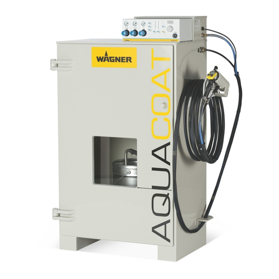
- Page 1 Translation of the Original Operating Manual GM 5020EACW High pressure Manual Version 02/2016 AirCoat Spraying System Non-fl ammable Liquids B_05900...
-
Page 3: Table Of Contents
4.1.1 Electrical Equipment 4.1.2 Personnel Qualifi cations 4.1.3 Safe Work Environment Safety Instructions for Staff 4.2.1 Safe Handling of WAGNER Spray Devices 4.2.2 Grounding the Device 4.2.3 Product Hoses 4.2.4 Cleaning and Flushing 4.2.5 Handling Hazardous Liquids, Varnishes and Paints 4.2.6... - Page 4 EDITION 02/2016 ORDER NUMBER DOC 2366600 OPERATING MANUAL Table of Contents Controls 5.6.1 VM 5020W Control Unit 5.6.1.1 Operating Elements, Front Side 5.6.1.2 Connections on the Rear Side 5.6.2 Product Pressure Generator 5.6.2.1 Puma 28-40 PE+TG Pneumatic Piston Pump 5.6.2.2 Cobra 40-10 Double Diaphragm Pump 5.6.2.3 EvoMotion 20-30 Piston Pump 5.6.2.4 Working in Accordance with Pump's Operating Manual 5.6.3...
- Page 5 EDITION 02/2016 ORDER NUMBER DOC 2366600 OPERATING MANUAL Table of Contents Working 7.3.1 Checking the Spray Pattern (Without Electrostatics) 7.3.2 Starting the System 7.3.3 Spraying 7.3.4 Pressure Relief/Work Interruption 7.3.5 Flushing Out Clogged Round Jet Nozzles 7.3.6 Replacing Round Jet Nozzle's Nozzle Insert 7.3.7 Changing from AirCoat Round Jet to AirCoat Flat Jet 7.3.8...
- Page 6 EDITION 02/2016 ORDER NUMBER DOC 2366600 OPERATING MANUAL Table of Contents 10.4 Spray Gun 10.4.1 Tools 10.4.2 Disassembly of the Spray Gun 10.4.3 Cleaning the Parts After Disassembly 10.4.4 Assembling the Spray Gun 10.5 Disassembling VM 5020W Control Unit 10.6 Opening the Control Unit FUNCTION TEST AFTER THE REPAIR 11.1...
-
Page 7: About These Instructions
EDITION 02/2016 ORDER NUMBER DOC 2366600 OPERATING MANUAL ABOUT THESE INSTRUCTIONS PREFACE The operating manual contains information about safely operating, maintaining, cleaning and repairing the device. The operating manual is part of the device and must be available to the operating and service personnel. -
Page 8: Languages
EDITION 02/2016 ORDER NUMBER DOC 2366600 OPERATING MANUAL LANGUAGES The AquaCoat GM 5020EACW operating manual is available in the following languages: Language Order No. Language Order No. German 2363958 English 2366600 French 2366598 Italian 2366601 Spanish 2366599 1.3.1 OPERATING MANUALS FOR THE INDIVIDUAL COMPONENTS Puma 28-40 PE+TG piston pump operating manual Language Order No. -
Page 9: Abbreviations
EDITION 02/2016 ORDER NUMBER DOC 2366600 OPERATING MANUAL ABBREVIATIONS Order No. Order number Ultra high molecular weight polyethylene Spare part PTFE with graphite Marking in the spare parts lists Position AirCoat Number of pieces AirCoat electrostatic, water-based Wrench size Manual gun Low viscosity High voltage High viscosity... -
Page 10: Correct Use
- Piston pump, EvoMotion 20-30 (in accordance with the spare parts catalog) TYPE OF USE AquaCoat 5010/5020 GM 5020EACW can be used to spray liquid, non-fl ammable products, in particular non-fl ammable coating products in accordance with Chapter 2.5. WAGNER forbids any other use! USE IN AN EXPLOSION HAZARD AREA The device is not suitable for use in potentially explosive areas. -
Page 11: Processible Working Materials
If the cleaning and fl ushing agents also align with this category, the system may be used. Example of non-combustible liquid: No more than 35 weight percent, 1:1 butylglycol/n-propanol, rest water. Please contact your local WAGNER dealer and the lacquer manufacturer if you encounter application problems. -
Page 12: Reasonably Foreseeable Misuse
EDITION 02/2016 ORDER NUMBER DOC 2366600 OPERATING MANUAL REASONABLY FORESEEABLE MISUSE The forms of misuse listed below may result in physical injury or property damage: coating work pieces which are not grounded; unauthorized conversions or modifi cations to the system; working with combustible coating products;... -
Page 13: Identification
OPERATING MANUAL IDENTIFICATION CE IDENTIFICATION The device may not be used in potentially explosive areas. TYPE PLATES AquaCoat cabinet 1 Device type J. WAGNER AG Industriestrasse 22 2 Input voltage CH-9450 ALTSTÄTTEN MADE IN SWITZERLAND 3 Input power AquaCoat Gerätetyp / Type:... -
Page 14: Safety Signage
B_05875 3 Maximum high voltage / Energy 4 Maximum product pressure 5 Maximum air pressure 6 In compliance with EN 50059 J. Wagner AG 7 For electrostatic application of water-based lacquers GM 5020EACW geprüft nach EN 50059 Art. Nr.: 2362837 max. -
Page 15: General Safety Instructions
EDITION 02/2016 ORDER NUMBER DOC 2366600 OPERATING MANUAL GENERAL SAFETY INSTRUCTIONS SAFETY INSTRUCTIONS FOR THE OPERATOR Keep this operating manual at hand near the device at all times. Always follow local regulations concerning occupational safety and accident prevention. 4.1.1 ELECTRICAL EQUIPMENT Electrical devices and equipment To be provided in accordance with the local safety requirements with regard to the operating mode and ambient infl uences. -
Page 16: Safety Instructions For Staff
- In the event of functional faults, remedy the fault as described in the "Troubleshooting" chapter. If needed, the liquid ejection devices must be checked by experts (e.g., WAGNER service technician) at least every 12 months to ensure they are safe for work in accordance with the DGUV regulation 100-500. -
Page 17: Grounding The Device
EDITION 02/2016 ORDER NUMBER DOC 2366600 OPERATING MANUAL In the event of skin injuries caused by paint or fl ushing agents: Note the paint or fl ushing agent that you have been using. Consult a doctor immediately. Avoid risk of injury from recoil forces: Ensure that you have firm footing when operating the spray gun. -
Page 18: Cleaning And Flushing
EDITION 02/2016 ORDER NUMBER DOC 2366600 OPERATING MANUAL Several liquids have a high expansion coeffi cient. In some cases their volume can rise with consequent damage to pipes, fi ttings, etc. and cause fl uid leakage. When the pump sucks liquid from a closed tank, ensure that air or a suitable gas can enter the tank. -
Page 19: Handling Hazardous Liquids, Varnishes And Paints
EDITION 02/2016 ORDER NUMBER DOC 2366600 OPERATING MANUAL 4.2.5 HANDLING HAZARDOUS LIQUIDS, VARNISHES AND PAINTS When preparing or working with lacquer and when cleaning the device, follow the working instructions of the manufacturer of the lacquers, solvents and cleaning agents being used. -
Page 20: Description
EDITION 02/2016 ORDER NUMBER DOC 2366600 OPERATING MANUAL DESCRIPTION COMPONENTS AquaCoat with Puma 28-40 piston pump 20 21 B_05850 Pos Designation AquaCoat cabinet Cabinet door VM 5020W control unit GM 5020EACW spray gun Hose set EACW Product hose (Puma: from high-pressure fi lter to spray gun; Cobra: from high-pressure fi lter to potential equalization connection (33)) High-voltage generator (high-voltage cascade) Air inlet with ball valve... - Page 21 EDITION 02/2016 ORDER NUMBER DOC 2366600 OPERATING MANUAL AquaCoat with Cobra 40-10 double diaphragm pump 20 21 13/14 B_05851 Pos Designation Product pressure generator (pump) High-pressure fi lter Suction system Product tank (Puma: metallic product tank; Cobra: hopper) Grounding bolt on the cabinet door Grounding band in the cabinet door Electrical door switch Pneumatic door switch...
- Page 22 EDITION 02/2016 ORDER NUMBER DOC 2366600 OPERATING MANUAL AquaCoat with EvoMotion 20-30 piston pump B_05887 Pos Designation Pos Designation AquaCoat cabinet 14 Metallic product tank Cabinet door 15 Grounding bolt on the cabinet door VM 5020W control unit 16 Grounding band in the cabinet door GM 5020EACW spray gun 17 Electrical door switch Hose set EACW...
-
Page 23: Mode Of Operation
EDITION 02/2016 ORDER NUMBER DOC 2366600 OPERATING MANUAL AquaCoat cabinet 34 35 RH side wall (from the inside) Pos Designation Grounding switch Grounding cylinder Leakage resistance 3 GOhm Potential equalization connection of the stripped part of the product hose (for Cobra) Passageway for product hose Connection for grounding cable for grounding the conductive sheath of the product hose. -
Page 24: Protective And Monitoring Equipment
EDITION 02/2016 ORDER NUMBER DOC 2366600 OPERATING MANUAL PROTECTIVE AND MONITORING EQUIPMENT WARNING Protective and monitoring equipment! Risk of injury and damage to the device. Protective and monitoring equipment must not be removed, modifi ed or rendered unusable. Regularly check for perfect functioning. If defects are detected on protective and monitoring equipment, the system must not be operated until these defects are remedied. - Page 25 EDITION 02/2016 ORDER NUMBER DOC 2366600 OPERATING MANUAL AquaCoat cabinet To achieve an optimal application effi ciency, the lacquer supply (lacquer tank and pump) is brought to high-voltage potential in an insulated cabinet. The interior of the cabinet, connected to high voltage, is protected by double (redundant) safety elements before touching.
-
Page 26: Scope Of Delivery
EDITION 02/2016 ORDER NUMBER DOC 2366600 OPERATING MANUAL SCOPE OF DELIVERY Basic device AquaCoat basic device 5020 5010 5020G 5010G Designation Order No. Order No. Order No. Order No. AquaCoat basic device: Cabinet including 2363292 2363401 2363734 2363736 VM 5020W control unit The scope of delivery of a basic device includes: AquaCoat GM 5020EACW Operating manual, German 2363958... -
Page 27: Basic Sets
Pos System component Order No. AquaCoat cabinet with VM 5020W control unit ✓ ✓ ✓ AquaCoat 5020 manual basic device 2363292 ✓ AquaCoat 5010 manual basic device 2363401 AquaCoat 5020G manual basic device 2363734 AquaCoat 5010G manual basic device 2363736 Pomp set ✓... -
Page 28: Technical Data
Sound pressure level When the cabinet is closed: The values are 10 – 12 dB(A) lower. Weight AquaCoat 5010: 62 kg; 136.7 lb (without product tank and pump) AquaCoat 5020: 70 kg; 154.3 lb Dimensions AquaCoat 5010... -
Page 29: Vm 5020W Control Unit
EDITION 02/2016 ORDER NUMBER DOC 2366600 OPERATING MANUAL 5.5.1 VM 5020W CONTROL UNIT 115 VAC–230 VAC Input voltage 50 Hz/60 Hz Input power Max. 40 W Output voltage Max. 20 Output current Max. 1.0 High voltage Max. 70 Spray current Max. -
Page 30: Gm 5020Eacw Spray Gun
EDITION 02/2016 ORDER NUMBER DOC 2366600 OPERATING MANUAL 5.5.3 GM 5020EACW SPRAY GUN Maximum air pressure 0.8 MPa; 8 bar; 116 psi Maximum product pressure 25 MPa; 250 bar; 3,626 psi Fluid inlet NPSM 1/4"-18 Air connection G 1/4" A Weight (without hose set) 700 g;... -
Page 31: Electric Block Diagram, Aquacoat
EDITION 02/2016 ORDER NUMBER DOC 2366600 OPERATING MANUAL 5.5.4 ELECTRIC BLOCK DIAGRAM, AQUACOAT VM 5020W control unit Earth Grounding Dat dis Dat sw Earth mon Spray gun with Power supply Coil + Coil - high-voltage cascade Cabinet HV-Cascade white white orange Door switch Product hose... -
Page 32: Controls
EDITION 02/2016 ORDER NUMBER DOC 2366600 OPERATING MANUAL CONTROLS 5.6.1 VM 5020W CONTROL UNIT The assembled spray system can be operated and regulated with the VM 5020W control unit. 5.6.1.1 OPERATING ELEMENTS, FRONT SIDE 24 25 Zerstäuberluft Mat. Druckregler Pumpe Atomizing air Mat. - Page 33 EDITION 02/2016 ORDER NUMBER DOC 2366600 OPERATING MANUAL Illuminated display "Spray current" Push button: "High voltage" For activating the function. The high voltage is set with the control dial (2) and is indicated in the LED display (27). - Adjusting range: 5–70 kV. - Resolution: 1 kV.
- Page 34 EDITION 02/2016 ORDER NUMBER DOC 2366600 OPERATING MANUAL 24 25 Zerstäuberluft Mat. Druckregler Pumpe Atomizing air Mat. pressure reg. Pump μA POWER AquaCoat B_03364 19 Push button "Recipe 3" 20 Illuminated display "Recipe 3" Illuminates if recipe 3 is used. 21 Illuminated display "High voltage"...
-
Page 35: Connections On The Rear Side
To connect a spray gun. 31 Door switch connection Connection for the door switch cable. 32 Cover of the service connection For WAGNER service personnel only! 33 Connection pump air Hose connector 10 mm; 0.39 inches. 34 Product pressure regulator connection (not used for AirCoat systems) Hose connector 8 mm;... -
Page 36: Product Pressure Generator
EDITION 02/2016 ORDER NUMBER DOC 2366600 OPERATING MANUAL 5.6.2 PRODUCT PRESSURE GENERATOR 5.6.2.1 PUMA 28-40 PE+TG PNEUMATIC PISTON PUMP The pump is equipped with a special AquaCoat compressed air connection (see below). All other relevant information can be found in the IceBreaker-operating manual (Order No. see Chapter 1.3.1). AquaCoat compressed air connection for Puma The AquaCoat control unit controls the pressure air ("Pomp pressure"... -
Page 37: Cobra 40-10 Double Diaphragm Pump
EDITION 02/2016 ORDER NUMBER DOC 2366600 OPERATING MANUAL 5.6.2.2 COBRA 40-10 DOUBLE DIAPHRAGM PUMP The pump is equipped with a special AquaCoat compressed air connection (see below). All other relevant information can be found in the Cobra operating manual (Order No., see Chapter 1.3.1). AquaCoat compressed air connection for Cobra The AquaCoat control unit controls the pressure air ("Pomp pressure"... -
Page 38: Evomotion 20-30 Piston Pump
EDITION 02/2016 ORDER NUMBER DOC 2366600 OPERATING MANUAL 5.6.2.3 EVOMOTION 20-30 PISTON PUMP The pump is equipped with a special AquaCoat compressed air connection (see below). All other relevant information can be found in the EvoMotion operating manual (Order No., see Chapter 1.3.1). AquaCoat compressed air connection for EvoMotion The AquaCoat control unit controls the pressure air ("Pomp pressure"... -
Page 39: Gm 5020Eacw Spray Gun
EDITION 02/2016 ORDER NUMBER DOC 2366600 OPERATING MANUAL 5.6.3 GM 5020EACW SPRAY GUN B_04362 Description Description Suspension hook Trigger lock Display (spray current and recipe) Trigger lever Display standby and fault Round jet nozzle adapter Operating button (standby and recipe change) (see accessories in Chapter 13.1) Union nut with protection against contact Round jet nozzle insert... -
Page 40: Securing The Spray Gun Against Actuation
EDITION 02/2016 ORDER NUMBER DOC 2366600 OPERATING MANUAL 5.6.3.1 SECURING THE SPRAY GUN AGAINST ACTUATION Secure the spray gun against actuation: Use the trigger lock (11) to engage the trigger (12). Note: To secure the entire system, pressure must be relieved as described in Chapter 7.3.4. 5.6.3.2 FUNCTIONING OF THE SPRAY GUN When the spray gun is connected to the control unit and the... - Page 41 EDITION 02/2016 ORDER NUMBER DOC 2366600 OPERATING MANUAL The trigger can be used to activate, one after the other, the various functions of the spray gun. Distance Description AirCoat air opens. AirCoat air opened and electrostatic (high voltage) activated. Display (2) for "spray current" on the spray gun activated.
-
Page 42: Spraying Procedure For Aircoat Round Spray
EDITION 02/2016 ORDER NUMBER DOC 2366600 OPERATING MANUAL 5.6.3.3 SPRAYING PROCEDURE FOR AIRCOAT ROUND SPRAY In the AirCoat procedure, the spray product is atomized at a pressure of 3 - 15 MPa; 30 - 150 bar; 435 - 2,176 psi. The air at 0-0.25 MPa; 0-2.5 bar; 0-36 psi produces a soft jet. The spray jet diameter can be adjusted by turning the nozzle nut. -
Page 43: Electrostatic Effect
EDITION 02/2016 ORDER NUMBER DOC 2366600 OPERATING MANUAL 5.6.3.5 ELECTROSTATIC EFFECT The in-system electrically loaded paint particles atomized by the spray gun are transported to the grounded object by kinetic and electrostatic energy where they adhere, fi nely distributed on the object being sprayed. Paint particle Object to be sprayed is grounded Advantages... -
Page 44: Assembly And Commissioning
EDITION 02/2016 ORDER NUMBER DOC 2366600 OPERATING MANUAL ASSEMBLY AND COMMISSIONING TRAINING ASSEMBLY/COMMISSIONING STAFF WARNING Incorrect installation/operation! Risk of injury and damage to the device. The assembly and commissioning staff must have the technical skills to safely commission the device. When assembling, commissioning and carrying out all work, read and follow the operating manuals and safety regulations for the additionally required system components. -
Page 45: Transportation
EDITION 02/2016 ORDER NUMBER DOC 2366600 OPERATING MANUAL TRANSPORTATION For underframe with rolls: The device can be moved on the rollers for short distances. Without underframe: The device can be transported using a pallet jack. Use the recessed area on the underside of the cabinet for this purpose. WARNING Inclined ground! Risk of accidents if the device rolls away/falls. -
Page 46: Assembling The Aquacoat System
EDITION 02/2016 ORDER NUMBER DOC 2366600 OPERATING MANUAL 6.5.1 ASSEMBLING THE AQUACOAT SYSTEM Accessories (option) 1. - Mount underframe with rolls, according to the assembly manual 2367143. - Mount hose holder in accordance with Chapter 14.5.4. - Mount gun holder in accordance with Chapter 14.5.5. - Place tub insert into AquaCoat cabinet. - Page 47 EDITION 02/2016 ORDER NUMBER DOC 2366600 OPERATING MANUAL Hose set 9. Mount hose set on the cabinet in accordance with Chapter 8.2.4 (assembly). Secure cables and hoses 10. Secure al cables and hoses with cable ties in the AquaCoat cabinet. The door switch moves up and down on the RH cabinet wall.
-
Page 48: Ventilation Of The Spray Booth
EDITION 02/2016 ORDER NUMBER DOC 2366600 OPERATING MANUAL 6.5.2 VENTILATION OF THE SPRAY BOOTH The electrostatic spraying equipment may only be operated in defi ned spraying areas and in accordance with the EN 12215 standard or under comparable ventilation conditions. The electrostatic spraying equipment must be locked to the technical ventilation so that the coating product supply and the high voltage are not eff ective as long as the technical ventilation is not operated with the minimum exhaust air volume fl ow or a larger exhaust... -
Page 49: Product Supply
EDITION 02/2016 ORDER NUMBER DOC 2366600 OPERATING MANUAL 6.5.4 PRODUCT SUPPLY NOTICE Impurities in the spraying system! Spray gun blockage, products harden in the spraying system. Flush the spray gun and paint supply with a suitable fl ushing agent. DANGER Bursting hose, bursting threaded joints! Danger to life from injection of product. -
Page 50: Grounding
EDITION 02/2016 ORDER NUMBER DOC 2366600 OPERATING MANUAL GROUNDING It is important for systems safety and to achieve an optimum coating that all system components such as work pieces, conveyors, paint supply, control unit and booth or spraying stand are perfectly grounded. WARNING Heavy paint mist if grounding is insuffi cient! Danger of poisoning. - Page 51 EDITION 02/2016 ORDER NUMBER DOC 2366600 OPERATING MANUAL Grounding scheme (example) Conveyor Work piece < 1 MΩ max. Spraying stand B_05896 Signal ground Signal ground Floor, static dissipative Minimum cable cross-section AquaCoat cabinet 4 mm²; AWG 12 Conveyor 16 mm²; AWG 6 Spray booth 16 mm²;...
-
Page 52: Safety Checks
EDITION 02/2016 ORDER NUMBER DOC 2366600 OPERATING MANUAL SAFETY CHECKS Carry out safety checks in accordance with Chapter 8.2.3. PREPARATION OF WATER-BASED LACQUER The viscosity of the lacquer is of great importance. The best spraying results are obtained with values between 25 and 40 DIN/4 seconds (measured in immersion fl ow cup DIN 4 mm; 0.16 inches). -
Page 53: Commissioning
EDITION 02/2016 ORDER NUMBER DOC 2366600 OPERATING MANUAL COMMISSIONING 6.9.1 SAFETY INSTRUCTIONS Observe the safety instructions in Chapter 4, Chapter 7.2 and Chapter 8.1.2. Only metal tanks may be used for product and fl ushing agents, no plastic tanks. 6.9.2 PREPARATION Before every start-up, the following points should be observed as laid down in the operating manual:... -
Page 54: Commissioning
EDITION 02/2016 ORDER NUMBER DOC 2366600 OPERATING MANUAL 6.9.3 COMMISSIONING 6.9.3.1 AQUACOAT WITH PUMA 28-40 OR EVOMOTION 20-30 Check the unit for leaks 1. Place metal tank (14) containing a suitable medium (e.g., fl ushing agent or water) in the AquaCoat cabinet. 2. - Page 55 EDITION 02/2016 ORDER NUMBER DOC 2366600 OPERATING MANUAL Preparation for spraying Fill the metal product tank (14) with lacquer and place in the cabinet. Immerse in tank the suction system (13). Clamp the potential equalization line (22) to the product tank (14). Connect the AquaCoat system to the electric socket with the electric cable (9).
-
Page 56: Aquacoat With Cobra 40-10 Double Diaphragm Pump
EDITION 02/2016 ORDER NUMBER DOC 2366600 OPERATING MANUAL 6.9.3.2 AQUACOAT WITH COBRA 40-10 DOUBLE DIAPHRAGM PUMP 20 21 13/14 B_05851 CAUTION Electrical discharge when using coated product tanks! Risk of injury; product charge not optimal. Ensure that the metal part of the tank is connected to the potential equalization line (e.g., remove coating from around the connection point). -
Page 57: Verifying A Safe Operational Condition
EDITION 02/2016 ORDER NUMBER DOC 2366600 OPERATING MANUAL Check the unit for leaks 1. Clamp the potential equalization line (22) to pump's product connection. 2. Fill the upper tank (14) with a suitable medium (e.g., fl ushing agent or water). 3. -
Page 58: Operation
EDITION 02/2016 ORDER NUMBER DOC 2366600 OPERATING MANUAL OPERATION TRAINING THE OPERATING STAFF WARNING Incorrect operation! Risk of injury and damage to the device. The operating staff must be qualifi ed to operate the entire system. The operating staff must be familiar with the potential risks associated with improper behavior as well as the necessary protective devices and measures. -
Page 59: Emergency Deactivation For Puma
EDITION 02/2016 ORDER NUMBER DOC 2366600 OPERATING MANUAL 7.2.1 EMERGENCY DEACTIVATION FOR PUMA In the case of unforeseen occurrences, proceed as follows: 1. Close main tap (1). 2. Switch off control unit (2) at main switch (3). 3. Open cabinet door (4). 4. -
Page 60: Emergency Deactivation For Cobra
EDITION 02/2016 ORDER NUMBER DOC 2366600 OPERATING MANUAL 7.2.2 EMERGENCY DEACTIVATION FOR COBRA In the case of unforeseen occurrences, proceed as follows: 1. Close main tap (1). 2. Switch off control unit (2) at main switch (3). 3. Open cabinet door (4). 4. -
Page 61: Emergency Deactivation For Evomotion
EDITION 02/2016 ORDER NUMBER DOC 2366600 OPERATING MANUAL 7.2.3 EMERGENCY DEACTIVATION FOR EVOMOTION In the case of unforeseen occurrences, proceed as follows: 1. Close main tap (1). 2. Switch off control unit (2) at main switch (3). 3. Open cabinet door (4). 4. -
Page 62: General Rules For Making Adjustments To The Spray Gun
EDITION 02/2016 ORDER NUMBER DOC 2366600 OPERATING MANUAL 7.2.4 GENERAL RULES FOR MAKING ADJUSTMENTS TO THE SPRAY GUN DANGER High-voltage fi eld! Danger to life from malfunction of heart pacemakers. Make sure that persons with pacemakers: Do not work with the electrostatic spray gun. Do not enter the high-voltage area. -
Page 63: Electrical Discharge
EDITION 02/2016 ORDER NUMBER DOC 2366600 OPERATING MANUAL 7.2.4.1 ELECTRICAL DISCHARGE In the nozzle area of the spray gun electrical discharges can occur. They are completely non-hazardous for human health. However, they can cause a shock reaction. CAUTION Electrical discharge! Shock reaction. -
Page 64: Working
EDITION 02/2016 ORDER NUMBER DOC 2366600 OPERATING MANUAL WORKING Ensure that: the regular safety checks are carried out in accordance with Chapter 8.2.3, commissioning is carried out in accordance with Chapter 6.9. Zerstäuberluft Mat. Druckregler Pumpe Atomizing air Mat. pressure reg. Pump μA POWER... - Page 65 EDITION 02/2016 ORDER NUMBER DOC 2366600 OPERATING MANUAL Flat jet method Setting the Spray Pattern Using the Atomizing Air Regulator (11) The atomizing air regulator regulates the air supply (shaping and atomizing air) to the gun. B_00071 No air Not enough air Correct amount of air Spray pattern and air regulation Air regulation regulates the ratio of shaping/atomizing air.
-
Page 66: Starting The System
EDITION 02/2016 ORDER NUMBER DOC 2366600 OPERATING MANUAL 7.3.2 STARTING THE SYSTEM Zerstäuberluft Mat. Druckregler Pumpe Atomizing air Mat. pressure reg. Pump μA POWER AquaCoat B_03371 B_05900 VM 5020W control unit 1. Set the main switch (1) to position 1. During the start-up phase, the device automatically performs an internal function test and then automatically switches to recipe 1 (15). -
Page 67: Spraying
EDITION 02/2016 ORDER NUMBER DOC 2366600 OPERATING MANUAL 7.3.3 SPRAYING 1. Secure gun with trigger lock and insert the desired nozzle. 2. Commissioning the system see Chapter 7.3.2. AirLess spraying 3. Turn atomizing air regulator (11) all the way down. 4. -
Page 68: Pressure Relief/Work Interruption
EDITION 02/2016 ORDER NUMBER DOC 2366600 OPERATING MANUAL 7.3.4 PRESSURE RELIEF/WORK INTERRUPTION The pressure must always be relieved when: - The spraying tasks are fi nished. - Servicing the system. - Carrying out cleaning tasks on the system. - Moving the system to another location. - Something needs to be checked on the system. -
Page 69: Flushing Out Clogged Round Jet Nozzles
EDITION 02/2016 ORDER NUMBER DOC 2366600 OPERATING MANUAL 7.3.5 FLUSHING OUT CLOGGED ROUND JET NOZZLES 1. Use nozzle spanner (2) to loosen nozzle insert (1) by a half turn. 2. Remove the nozzle spanner and briefl y actuate trigger. 3. After fl ushing the nozzle, re-tighten the nozzle insert. B_03531 7.3.6 REPLACING ROUND JET NOZZLE'S NOZZLE INSERT... -
Page 70: Changing From Aircoat Round Jet To Aircoat Flat Jet
EDITION 02/2016 ORDER NUMBER DOC 2366600 OPERATING MANUAL 7.3.7 CHANGING FROM AIRCOAT ROUND JET TO AIRCOAT FLAT JET 1. Thoroughly fl ush the spray gun (1) with fl ushing agent Chapter 8.1.3. 2. Relieve pressure Chapter 7.3.4. 3. Secure the spray gun (1) using the trigger lock. Changing from round jet to fl at jet 4. - Page 71 EDITION 02/2016 ORDER NUMBER DOC 2366600 OPERATING MANUAL B_03534...
- Page 72 EDITION 02/2016 ORDER NUMBER DOC 2366600 OPERATING MANUAL...
-
Page 73: Replacing The Aircoat Flat Jet Nozzles
EDITION 02/2016 ORDER NUMBER DOC 2366600 OPERATING MANUAL 7.3.8 REPLACING THE AIRCOAT FLAT JET NOZZLES 1. Switch off control unit. 2. Relieve pressure Chapter 7.3.4. 3. Secure the spray gun (1) using the trigger lock (14). 4. Unscrew union nut completely (12) and remove air cap (10). 5. -
Page 74: Eliminate Nozzle Clogging
EDITION 02/2016 ORDER NUMBER DOC 2366600 OPERATING MANUAL 7.3.10 ELIMINATE NOZZLE CLOGGING 1. Switch off control unit. 2. Relieve pressure Chapter 7.3.4. 3. Secure the spray gun (1) using the trigger lock (14). 4. Unscrew union nut (12) with air cap (10) and ACF5000 nozzle (11). 5. - Page 75 EDITION 02/2016 ORDER NUMBER DOC 2366600 OPERATING MANUAL B_04790 ACF5000 nozzle in spray position ACF5000 nozzle in cleaning position...
-
Page 76: Vm 5020W Control Unit Start Up
EDITION 02/2016 ORDER NUMBER DOC 2366600 OPERATING MANUAL 7.3.11 VM 5020W CONTROL UNIT START UP 1. Turn switch to position 1. μA 2. All LEDs on the control unit illuminate POWER POWER for approximately 1 second. AquaCoat B_03372 3. The hardware version and the software version are shown on the display alternately in succession. -
Page 77: Setting And Saving Recipes
EDITION 02/2016 ORDER NUMBER DOC 2366600 OPERATING MANUAL 7.3.12 SETTING AND SAVING RECIPES Nominal values for the high voltage (kV) and for the spray current limiter (μA) are stored in a recipe. As standard, the following values are saved in the factory in the 3 storage places available for recipes: Recipe No. -
Page 78: Setting The High Voltage
EDITION 02/2016 ORDER NUMBER DOC 2366600 OPERATING MANUAL 7.3.13 SETTING THE HIGH VOLTAGE Procedure: 1. Press the "High-voltage" button (7) to adjust the high voltage. μA The LED (8) indicates that high voltage POWER POWER is selected. AquaCoat B_03375 2. The high voltage can now be adjusted using the universal rotary controller (2) between 5 to 70 kV with a resolution μA... -
Page 79: Setting The Current Limitation
EDITION 02/2016 ORDER NUMBER DOC 2366600 OPERATING MANUAL 7.3.14 SETTING THE CURRENT LIMITATION Procedure: 1. Press the "Current Limitation" button (5) to μA adjust the limitation of the spray current. The LED (6) indicates that current limitation POWER POWER is selected. AquaCoat B_03377 2. -
Page 80: Display During Spraying
EDITION 02/2016 ORDER NUMBER DOC 2366600 OPERATING MANUAL 7.3.15 DISPLAY DURING SPRAYING Ready to spray using R2 recipe (see picture below). Control unit in standby position. The nominal value LEDs illuminate as dots and the high-voltage value is digitally displayed in the LED display. -
Page 81: Standby Mode
EDITION 02/2016 ORDER NUMBER DOC 2366600 OPERATING MANUAL 7.3.16 STANDBY MODE If you want to spray without high voltage, select standby mode. Briefl y press the "Standby" push button (3), LED (4) will illuminate. All other LEDs are extinguished. μA POWER POWER AquaCoat... -
Page 82: Operating Hours Counter/Service Display
EDITION 02/2016 ORDER NUMBER DOC 2366600 OPERATING MANUAL 7.3.17 OPERATING HOURS COUNTER/SERVICE DISPLAY Two hour counters are integrated into the control unit. The absolute counter measures the ongoing hours of operation of the spray gun and with the maintenance hours counter, maintenance intervals can be determined and monitored for the spray gun. -
Page 83: Service Display Setup
EDITION 02/2016 ORDER NUMBER DOC 2366600 OPERATING MANUAL 7.3.18 SERVICE DISPLAY SETUP When the device is fi rst used, the function for the service interval is deactivated. This function can be activated with the "R3" push button (19). The maintenance interval limit can be set within a range of 0 to 999 hours. -
Page 84: Carry Out Service" Display
EDITION 02/2016 ORDER NUMBER DOC 2366600 OPERATING MANUAL 7.3.19 "CARRY OUT SERVICE" DISPLAY μA POWER POWER AquaCoat B_03385 Prerequisite The "Service interval limit" function is activated (see Chapter 7.3.18). "Service spray gun" Once the time for the defi ned maintenance interval has expired, the LED display (26) starts to fl ash. -
Page 85: Device Configuration
EDITION 02/2016 ORDER NUMBER DOC 2366600 OPERATING MANUAL DEVICE CONFIGURATION 7.4.1 OVERVIEW OF PARAMETERS Parameter Value Description The target values for high voltage in kV and current limitation in μA are adjusted at (factory setting) the front control panel of the control unit. - The set values for high voltage in kV and current limitation in μA are predefi ned using the interface's two analog power... -
Page 86: Access To The Device Configuration Mode
EDITION 02/2016 ORDER NUMBER DOC 2366600 OPERATING MANUAL 7.4.2 ACCESS TO THE DEVICE CONFIGURATION MODE Procedure: 1. Switch device to "Standby" by pressing the "Standby" key (3). The "Standby" LED (4) lights up yellow. μA POWER POWER AquaCoat B_03381 2. Press and hold the "Service" push button (25). -
Page 87: Setting Example "Parameter C13
For ease of operation, the confi guration settings are divided into three groups. The fi rst group is for the end user; the other two groups, protected by a password, are reserved for WAGNER Service and the WAGNER production sites or the WAGNER Service Center, which have the necessary infrastructure. - Page 88 EDITION 02/2016 ORDER NUMBER DOC 2366600 OPERATING MANUAL 26 25 μA POWER POWER AquaCoat B_03510 The fl ashing LED display "Service" (26) indicates that the parameter value "OFF" in the display (27) can be changed by the universal control dial (2). Possible values for parameter C13 are "on", "off "...
-
Page 89: External Interface
EDITION 02/2016 ORDER NUMBER DOC 2366600 OPERATING MANUAL EXTERNAL INTERFACE The control unit is equipped with an interface. The electrical door switch is wired as standard at the 8-pin socket on the back of the VM 5020W control unit (also refer to the J3 plug in the block diagram, Chapter 5.5.4). This socket also off ers the functions designated in the following illustration. - Page 90 EDITION 02/2016 ORDER NUMBER DOC 2366600 OPERATING MANUAL Pin no. Designation Description Potential-free contact (button) between pin 2 and pin 8 (ground) 2 in Fault reset - If there is a fault, it can be acknowledged by pressing a button. - Acknowledgement is only given via the negative edge.
-
Page 91: Cleaning And Maintenance
EDITION 02/2016 ORDER NUMBER DOC 2366600 OPERATING MANUAL CLEANING AND MAINTENANCE CLEANING 8.1.1 CLEANING STAFF Cleaning work should be undertaken regularly and carefully by qualifi ed and trained staff . They should be informed of specifi c hazards during their training. The following hazards may arise during cleaning work: - Health hazard from inhaling solvent vapors - Use of unsuitable cleaning tools and aids... -
Page 92: Flushing And Cleaning The System
DANGER Incorrect maintenance/repair! Danger to life and equipment damage. Only a WAGNER service center or a suitably trained person may carry out repairs and replace parts. Only repair and replace parts that are listed in the "Spare parts" chapter and that are assigned to the unit. - Page 93 EDITION 02/2016 ORDER NUMBER DOC 2366600 OPERATING MANUAL The AquaCoat spray system must be cleaned and rinsed out every day. The cleaning and fl ushing agents must be compatible with the working material. WARNING Incompatibility of cleaning/fl ushing agent and working medium! Risk of explosion and danger of poisoning by toxic gases.
-
Page 94: Maintenance
- Carry out a function test, if required, in accordance with Chapter 11. According DGUV regulation 100-500: - The liquid ejection devices should be checked by an expert (e.g., WAGNER service technician) for their safe working conditions as required and at least every 12 months. -
Page 95: Safety Checks
EDITION 02/2016 ORDER NUMBER DOC 2366600 OPERATING MANUAL 8.2.3 SAFETY CHECKS 8.2.3.1 GROUNDING CHECK Every day Before starting work, carry out a visual check to ensure that the grounding connection is present in the AquaCoat cabinet and in all relevant components. 8.2.3.2 INSPECTING THE SAFETY ELEMENTS Every day... -
Page 96: Product Hoses, Tubes And Couplings
- 6 years from the date of the hose crimping (see fi tting embossing). - 10 years from the date of the hose imprinting. Fitting Hose imprinting Meaning Meaning embossing WAGNER Name/Manufacturer xxx bar Pressure Date of manufacture yymm Crimping date... -
Page 97: Changing The Spray Gun With Hose Set
EDITION 02/2016 ORDER NUMBER DOC 2366600 OPERATING MANUAL 8.2.4 CHANGING THE SPRAY GUN WITH HOSE SET B_05890 Puma Cobra EvoMotion Disassembly 1. Dismount the VM 5020W control unit as described in Chapter 10.5. 2. Rear of the control unit: Loosen the knurled nut on the gun cable (5) and remove plug. -
Page 98: Changing The Product Hose And/Or Air Hose
EDITION 02/2016 ORDER NUMBER DOC 2366600 OPERATING MANUAL 8.2.5 CHANGING THE PRODUCT HOSE AND/OR AIR HOSE 1. Loosen and unscrew clamping screw (1). 2. Loosen nut (2) and remove product hose from the attachment point. 3. Push protective hose (4) back. 4. -
Page 99: Troubleshooting And Rectification
- Spray gun cable not connected or - Connect spray gun cable defective - Spray gun not connected or defective - Contact the WAGNER Service Team Fault LED (24) lights up - See the following table - See the following table... - Page 100 - The cascade is defective - Check or replace cascade E21-E25 Exception error - Hardware defect has occurred - If problem persists, contact the WAGNER Service Team Door switch - Door open - Close door - Door switch defective - Check/replace door switch...
-
Page 101: Faults In The System
- Connect gun and gun cable/check for defect. - Check lacquer resistance (see Chapter 2.5). - Seal in end piece defective - Repair by WAGNER Service. - Air-passages damp - Clean and dry air passages. Back-spray - Object not grounded - Check grounding. -
Page 102: Repair Work
- Function test in accordance with Chapter 11. According DGUV regulation 100-500: - The liquid ejection devices should be checked by an expert (e.g., WAGNER service technician) for their safe working conditions as required and at least every 12 months. -
Page 103: Mounting Materials
EDITION 02/2016 ORDER NUMBER DOC 2366600 OPERATING MANUAL 10.3 MOUNTING MATERIALS In Chapter 14 the order numbers for device spare parts can be found, as well as for wearing parts such as seals. Use torques, greases and glues in accordance with Chapter 14. Spray gun in accordance with Chapter 10.4. -
Page 104: Disassembly Of The Spray Gun
EDITION 02/2016 ORDER NUMBER DOC 2366600 OPERATING MANUAL 10.4.2 DISASSEMBLY OF THE SPRAY GUN SW12 SW12 B_03537 Air hose When unscrewing the air hose, a second open-ended/box wrench must be used for bracing. Torx® 25 SW19 B_05884... - Page 105 - Pull out straight with suitable pliers. Possibly rotate clockwise simultaneously. - Thereafter, the fi tting must be replaced. If the fi tting is broken in the gun adapter, WAGNER Service must be contacted. Valve tip (27) Valve needle assembly tool, Loosen valve tip by hand using Order No.
- Page 106 EDITION 02/2016 ORDER NUMBER DOC 2366600 OPERATING MANUAL B_04796 O-ring (8): 1. Use screwdriver no. 1 to press under the O-ring. Air distribution (9): 1. Locate the start of the thread for recessed internal 2. Lever up the O-ring and threading.
-
Page 107: Cleaning The Parts After Disassembly
EDITION 02/2016 ORDER NUMBER DOC 2366600 OPERATING MANUAL 1. Loosen the oval head screw (3). 2. Pull the air valve (4) out off the drilled hole. Do not turn! Do not damage the cylindrical surfaces. Ideally press on the tappet from behind using a transversely held screwdriver, for example. -
Page 108: Assembling The Spray Gun
EDITION 02/2016 ORDER NUMBER DOC 2366600 OPERATING MANUAL 10.4.4 ASSEMBLING THE SPRAY GUN Mounting materials Order No. Description 9992698 Vaseline white PHHV II 9992511 Loctite 243 * Use Vaseline sparingly Only as required (if the seal was removed): press in using handle seal assembly tool (Order No. - Page 109 EDITION 02/2016 ORDER NUMBER DOC 2366600 OPERATING MANUAL Valve rod unit Set length adjusting measure X with withdrawal nut (7) and then fasten the threaded pin (6) using an Allen wrench SW2. B_04791 Wear gloves! The outside thread of the packing (9) must be free of lacquer.
- Page 110 EDITION 02/2016 ORDER NUMBER DOC 2366600 OPERATING MANUAL B_04792 Ensure the correct insertion position! Valve needle assembly tool, Order no. 2309368 B_04793 0.1 Nm 1.8 Nm Clamping screw assembly tool, Order No. 2325263 1. Move the valve rod to the rear position so that the sealing area does not become scratched (1).
- Page 111 EDITION 02/2016 ORDER NUMBER DOC 2366600 OPERATING MANUAL (sparingly) Clean and degrease the inside of the adapter and the cascade, SW19 then grease the cascade surface 2.5 Nm with Vaseline. B_05885 Fitting (25) Before assembling the product hose, check that no fi tting (25) is in the gun adapter! Check the fi tting for damage and replace if necessary (Order No.
- Page 112 EDITION 02/2016 ORDER NUMBER DOC 2366600 OPERATING MANUAL Push the trigger upward into the air valve piston. The recess in the trigger must engage correctly in the indentation of the piston. Torx® 25 B_03542 0.8 Nm Cover (5) The cover must be handled carefully and not be twisted Ensure the correct SW12...
- Page 113 EDITION 02/2016 ORDER NUMBER DOC 2366600 OPERATING MANUAL Flat jet nozzle Diverse nozzle sizes, see Chapter 13.2. Round jet nozzle Diverse nozzle sizes, see Chapter 13.1. B_03544 Air hose When screwing on the air hose, a second open-ended/ring spanner must be used for bracing.
-
Page 114: Disassembling Vm 5020W Control Unit
EDITION 02/2016 ORDER NUMBER DOC 2366600 OPERATING MANUAL 10.5 DISASSEMBLING VM 5020W CONTROL UNIT 1. Switch off control unit and open cabinet door (1). 2. Lock the compressed air supply and decompress the system. 3. Loosen and unscrew screw (2). 4. -
Page 115: Function Test After The Repair
EDITION 02/2016 ORDER NUMBER DOC 2366600 OPERATING MANUAL FUNCTION TEST AFTER THE REPAIR After all repairs, the AquaCoat system must be checked for safe condition before recommissioning. The necessary scope of inspection and testing depends on the repair carried out and must be documented by the repair staff . The system must not be fi lled with liquid for this function check. - Page 116 EDITION 02/2016 ORDER NUMBER DOC 2366600 OPERATING MANUAL Activities Aid tools 6. Check door switch - Open the cabinet door. - Switch on the control unit. - Switch air on. - Actuate the trigger on the spray gun. Electrical door switch test: - The high voltage must remain switched off .
-
Page 117: Function Tests For Spray Gun
EDITION 02/2016 ORDER NUMBER DOC 2366600 OPERATING MANUAL 11.1 FUNCTION TESTS FOR SPRAY GUN 11.1.1 AIR TEST Connect test or air hose to spray gun. The following air tests are to be carried out twice each: - at 0.1 MPa; 1 bar; 14.5 psi - at 0.8 MPa;... -
Page 118: Disposal
WAGNER or one of our dealers will take back your used WAGNER electric or electronic equipment and will dispose of it for you in an environmentally-friendly way. -
Page 119: Accessories
EDITION 02/2016 ORDER NUMBER DOC 2366600 OPERATING MANUAL ACCESSORIES 13.1 ROUND SPRAY NOZZLES Order No. Designation 2309902 ACWR 5000 round jet nozzle adapter (with nozzle spanner, without AC round jet nozzle insert) For details, see Chapter 14.5.2 B_03210 13.1.1 AIRCOAT ROUND JET NOZZLE INSERTS The round jet nozzles are especially suited to spray pipes, profi les and complex work pieces. -
Page 120: Acf5000 Aircoat Flat Jet Nozzles
EDITION 02/2016 ORDER NUMBER DOC 2366600 OPERATING MANUAL 13.2.1 ACF5000 AIRCOAT FLAT JET NOZZLES Bore mm; inch Order No. Marking Spray angle Application B 03163 395107 07/10 0.18; 0.007 10° Natural lacquer 395207 07/20 20° 395407 07/40 40° 395109 09/10 0.23;... - Page 121 EDITION 02/2016 ORDER NUMBER DOC 2366600 OPERATING MANUAL Bore mm; inch Order No. Marking Spray angle Application B 03163 395219 19/20 0.48; 0.019 20° Rust proofi ng paints 395319 19/30 30° Latex paints 395419 19/40 40° 395419 19/50 50° 395619 19/60 60°...
-
Page 122: Hoses And Gun Cables
EDITION 02/2016 ORDER NUMBER DOC 2366600 OPERATING MANUAL 13.3 HOSES AND GUN CABLES Note: Product hose Inside diameter DN 4 Product Nominal pressure 25 MPa; 250 bar; 3,626 psi B_03547 7.5 m; 24.6 ft Order No. Designation 2339187 Hose set, GM 5000EACW (7.5 m; 24.6 ft) Consists of: 2309468 Product hose EACW, complete (7.5 m;... - Page 123 EDITION 02/2016 ORDER NUMBER DOC 2366600 OPERATING MANUAL Pump side Hose colors Gray: Product hose Blue: Air hose Gun side (*) Heat and fuse protective hose ends and bend inwards by approximately 5 cm; 2 inches. (**) Fix the protective hose with cable ties on both sides only once at the product hose. (***) Fix the hose set within the protective hose approx.
-
Page 124: Miscellaneous
EDITION 02/2016 ORDER NUMBER DOC 2366600 OPERATING MANUAL 13.4 MISCELLANEOUS Order No. Designation High-voltage oil (10 ml; 10 cc) 353702 (for product hose assembly) 2319653 Protective gun coating B_03693 2309368 Valve needle assembly tool B_03451 2325263 Clamping screw assembly tool B_03681 128901 Nozzle spanner, ACR... - Page 125 EDITION 02/2016 ORDER NUMBER DOC 2366600 OPERATING MANUAL Order No. Designation 353050 Hose holder B_05892 Gun holder. 2359097 For assembly on hose holder 353050. B_05893 2326485 Wall mount, GM 5000E (left/right) B_03699 2359029 Underframe, 5020 with rolls 2364394 Underframe, 5010 with rolls B_05894 2364791 Tub insert, 5020...
-
Page 126: Spare Parts
DANGER Incorrect maintenance/repair! Danger to life and equipment damage. Only a WAGNER service center or a suitably trained person may carry out repairs and replace parts. Only repair and replace parts that are listed in the "Spare parts" chapter and that are assigned to the unit. -
Page 127: Aquacoat Basic Device
2367571 Hinge bolt 2358921 Securing ring 9922511 Instruction label, AquaCoat 5020 2359298 High-voltage warning sign, 50 mm 9952558 WAGNER label Type plate, AquaCoat Hexagon socket cylinder head screw 9900308 Control unit, VM 5020W 2362954 Label AquaCoat Connection fi elds 9935049... - Page 128 EDITION 02/2016 ORDER NUMBER DOC 2366600 OPERATING MANUAL Spare parts list for AquaCoat basic device 5020 5020G 5010 5010G Stk Designation Order No. Order No. Order No. Order No. Hexagon socket cylinder head screw 9900365 Pump support 2362723 Hexagon socket cylinder head screw 9900346 Washer 9920103...
- Page 129 EDITION 02/2016 ORDER NUMBER DOC 2366600 OPERATING MANUAL B_05945...
- Page 130 EDITION 02/2016 ORDER NUMBER DOC 2366600 OPERATING MANUAL Spare parts list for AquaCoat basic device 5020 5020G 5010 5010G Stk Designation Order No. Order No. Order No. Order No. Valve holder 2362721 Roller lever valve, RS-3-1/8 2362775 Hexagon nut, 0.5 d 9911005 Grounding plate 2362722...
- Page 131 EDITION 02/2016 ORDER NUMBER DOC 2366600 OPERATING MANUAL B_05955 B_05948 Spare parts list for AquaCoat basic device 5020 5020G 5010 5010G Stk Designation Order No. Order No. Order No. Order No. 2 m Hose, black 10 mm; 0.39 inch 9987076 1.9 m Hose, black 8 mm;...
-
Page 132: Vm 5020W Control Unit
EDITION 02/2016 ORDER NUMBER DOC 2366600 OPERATING MANUAL 14.2.1 VM 5020W CONTROL UNIT Spare parts list for VM 5020W control unit Order No. Designation 2362954 Control unit, VM 5020W Front panel, VM 5000W 2304459 Incremental encoder, type E33 2329441 Serrated lock washer, externally toothed 2304461 Rotary knob 2304462... - Page 133 EDITION 02/2016 ORDER NUMBER DOC 2366600 OPERATING MANUAL Spare parts list for VM 5020W control unit Order No. Designation Housing, VM 5020W 9951117 Delay-action fuse 1.0 AT 2348276 Fuse socket, FPG1 for 5x20 mm glass Cable loom, VM 5020W 9903306 Recessed head raised fi llister head screw, H form 9950330 Safety clip for device sockets...
- Page 134 EDITION 02/2016 ORDER NUMBER DOC 2366600 OPERATING MANUAL Spare parts list for VM 5020W control unit Order No. Designation 9910103 Hexagon nut 9922011 Serrated lock washer, externally toothed Print VM 5020W rear panel, complete 2365967 Including connector plug and socket 263400 Distance bush 9998769...
- Page 135 EDITION 02/2016 ORDER NUMBER DOC 2366600 OPERATING MANUAL Spare parts list for VM 5020W control unit Order No. Designation 2309112 Spacer 2312348 Hexagon lock nut 2317539 Print complete VM 5000 display. Including pos. 3. 9903312 Recessed head raised fi llister head screw, H form 2352818 Switching power supply, EPS-45-24 2360090...
- Page 136 EDITION 02/2016 ORDER NUMBER DOC 2366600 OPERATING MANUAL Spare parts list for VM 5020W control unit Order No. Designation 9998255 Straight threaded fi tting 9998675 Threaded plug, G1/8" 9956178 Switch 9998254 Screw-in fi tting, 8 mm -1/4" 9998987 Threaded fi tting, 10 mm – 1/4" 9998677 Pressure gauge, 0–10 bar RF40 (d40) 9992289...
- Page 137 EDITION 02/2016 ORDER NUMBER DOC 2366600 OPERATING MANUAL Spare parts list for VM 5020W control unit Order No. Designation 0.45 m 9987076 Hose, black 10 mm; 0.39 inch 0.30 m 9982078 Hose, black 8 mm; 0.32 inch 0.16 m 9982079 Hose, black 6 mm;...
-
Page 138: Pump Sets
EDITION 02/2016 ORDER NUMBER DOC 2366600 OPERATING MANUAL 14.3 PUMP SETS 14.3.1 PUMA 28-40 SET FOR AQUACOAT Air inlet behind the control unit 50 Nm; 37 lbft 25 Nm; 18 lbft Remove fi tting (is not needed) Lubricate all stainless steel fi ttings with Molykote , except those who explicitly request something diff erent (e.g., Loctite ). - Page 139 EDITION 02/2016 ORDER NUMBER DOC 2366600 OPERATING MANUAL Spare parts list for Puma 28-40 piston pump set for AquaCoat Order No. Designation 2363746 Puma 28-40 set for AquaCoat Piston pump Piston pump, Puma 28-40 PE/TG REM (without pressure regulator unit) Refer to the pump operating manual for details Air motor, Puma REM (without pressure regulator unit) 2335843...
-
Page 140: Cobra 40-10 Set For Aquacoat
EDITION 02/2016 ORDER NUMBER DOC 2366600 OPERATING MANUAL 14.3.2 COBRA 40-10 SET FOR AQUACOAT Air inlet behind the Connection for potential equalization control unit on the RH side wall Pos 13 Pos 15 Product hose to spray gun B_05951 Lubricate all stainless steel fi ttings with Molykote , except those who explicitly request something diff erent (e.g., Loctite ). - Page 141 EDITION 02/2016 ORDER NUMBER DOC 2366600 OPERATING MANUAL Spare parts list for Cobra 40-10 piston pump set for AquaCoat Order No. Designation 2363747 Cobra 40-10 set for AquaCoat Piston pump Cobra 40-10 double diaphragm pump, REM frame Refer to the pump operating manual for details 9999208 Male stud elbow, 10-1/4 9985685...
-
Page 142: Evomotion 20-30 Set For Aquacoat
EDITION 02/2016 ORDER NUMBER DOC 2366600 OPERATING MANUAL 14.3.3 EVOMOTION 20-30 SET FOR AQUACOAT 50 Nm; 37 lbft Remove fi tting (is not needed) DN16 B_05950 Lubricate all stainless steel fi ttings with Molykote , except those who explicitly request something diff erent (e.g., Loctite ). -
Page 143: Distributor For Evomotion
EDITION 02/2016 ORDER NUMBER DOC 2366600 OPERATING MANUAL Spare parts list for EvoMotion 20-30 Set for AquaCoat Order No. Designation 2363946 EvoMotion 20-30 set for AquaCoat Pistonp. EvoMotion 20-30 AQUA Refer to the pump operating manual for details 9992504 Release agent 9906036 Hexagon socket cylinder head screw 9920103... -
Page 144: Relief Combination, 270 Bar
EDITION 02/2016 ORDER NUMBER DOC 2366600 OPERATING MANUAL 14.3.4 RELIEF COMBINATION, 270 BAR 27 MPa; 270 bar; 3,916 psi 100 Nm 74 lbft B_04068 Spare parts list for relief combination 270 bar Order No. Designation 2329023 Relief combination 2324549 Relief housing 2323718 Hexagon plug 169248 Relief valve, complete 2324552... -
Page 145: Angled Inline Filter, 530 Bar
EDITION 02/2016 ORDER NUMBER DOC 2366600 OPERATING MANUAL 14.3.5 ANGLED INLINE FILTER, 530 BAR 53 MPa; 530 bar; 7,687 psi B_04071 Spare parts list for angled inline fi lter 270 bar Order No. Designation 2329026 Inline fi lter, HL DN6-PN530-G1/4"-SSt 2326045 Filter inlet housing, pre-assembled Filter insert, yellow (middle), 100 meshes per inch * 2315723 * Filter insert, red (fi ne), 200 meshes per inch –... -
Page 146: Gm 5020Eacw Spray Gun
EDITION 02/2016 ORDER NUMBER DOC 2366600 OPERATING MANUAL 14.4 GM 5020EACW SPRAY GUN Dismantling and assembly see Chapter 10 B_05970... - Page 147 EDITION 02/2016 ORDER NUMBER DOC 2366600 OPERATING MANUAL Spare parts list for GM 5020EACW spray gun Order No. Designation 2362841 GM 5020EACW Adapter GM 5000EACW, complete For details, see Chapter 14.4.1 2314361 Hook Handle ES 5000AC, complete For details, see Chapter 14.4.2 9900308 Hexagon socket cylinder head screw 2312183...
-
Page 148: Gm 5020Eacw Adapter
EDITION 02/2016 ORDER NUMBER DOC 2366600 OPERATING MANUAL 14.4.1 GM 5020EACW ADAPTER Dismantling and assembly see Chapter 10 123 ±0.1 mm 4.8425 ±0.004 inch B_05971... - Page 149 EDITION 02/2016 ORDER NUMBER DOC 2366600 OPERATING MANUAL Spare parts list End-piece GM 5020EACW Order No. Designation Adapter GM 5020EACW, complete 2309391 Air manifold ring, Air 2307180 O-ring, sheathed 2312175 Valve housing AC, complete 2312186 Valve needle AC, complete 2362840 Adapter, GM 5020EACW 9974166 O-ring...
-
Page 150: Gm 5000Eac Handle
EDITION 02/2016 ORDER NUMBER DOC 2366600 OPERATING MANUAL 14.4.2 GM 5000EAC HANDLE Dismantling and assembly see Chapter 10 B_04775... - Page 151 EDITION 02/2016 ORDER NUMBER DOC 2366600 OPERATING MANUAL Spare parts list for GM 5000EAC handle Order No. Designation Handle GM 5000EAC, complete 2307288 Nipple 9971025 O-ring 2307290 Hose holder 2312182 Plug, complete 2314270 Handle, complete 2307232 Adapter seal 2311952 Stop screw 2309825 Oval head screw with hexagon socket 2310692...
-
Page 152: Accessories Spare Parts Lists
EDITION 02/2016 ORDER NUMBER DOC 2366600 OPERATING MANUAL 14.5 ACCESSORIES SPARE PARTS LISTS 14.5.1 FAN SPRAY NOZZLES Flat jet nozzles spare parts list Order No. Designation 2315775 Union nut AC, complete 2309901 Air cap, ACWF 5000 - LV (red) 2314204 Air cap, ACWF 5000 - HV (blue) 2311777 Nozzle guard AC... -
Page 153: Underframe With Rolls
EDITION 02/2016 ORDER NUMBER DOC 2366600 OPERATING MANUAL 14.5.3 UNDERFRAME WITH ROLLS Spare parts list for underframe with rolls 5020 5020G 5010 5010G Stk Designation Order No. Order No. Order No. Order No. Underframe with rolls 2359029 2364394 Swivel castor support Crossbar Hexagon socket cylinder head screw 9900313... -
Page 154: Hose Holder
EDITION 02/2016 ORDER NUMBER DOC 2366600 OPERATING MANUAL 14.5.4 HOSE HOLDER Spare parts list for hose holder Order No. Designation 353050 Hose holder, complete 9935049 Connection fi elds Wearing parts B_05972 14.5.5 GUN HOLDER Spare parts list for gun holder Order No. -
Page 155: Level Monitor With Alarm Horn
EDITION 02/2016 ORDER NUMBER DOC 2366600 OPERATING MANUAL 14.5.6 LEVEL MONITOR WITH ALARM HORN Spare parts list for level monitor with alarm horn Order No. Designation 353053 Level monitor 3207739 30-liter niveau compensator 9999435 T-connection 9950615 Cable tie 3151777 Straight reduction 9999441 2/2-way valve 9943023... -
Page 156: D350 Drum Cover
EDITION 02/2016 ORDER NUMBER DOC 2366600 OPERATING MANUAL 14.5.7 D350 DRUM COVER Without With Spare parts list for D350 drum cover agitator agitator Designation Order No. Order No. Drum cover, D350 353054 353055 Cover, 365-A with plug 2304618 Bushing 2367311 Agitator, P300HS-L400x16-D100-M32 2304533 T-connection... -
Page 157: Warranty And Conformity Declarations
The manufacturer will not be held liable or will only be held partially liable if third-party accessories or spare parts have been used. With genuine WAGNER accessories and spare parts, you have the guarantee that all safety regulations are complied with. -
Page 158: Ce Declaration Of Conformity
Identifi cation: EC Certifi cate of Conformity The CE certifi cate of conformity is enclosed with this product. If needed, further copies can be ordered through your WAGNER dealer by specifying the product name and serial number. Order number: 2363961 15.4... - Page 160 Order No. 2366600 Edition 02/2016 Germany Phone Telefax E-mail Switzerland Phone Telefax More contact addresses on the internet at: Company/Locations/WAGNER worldwide Subject to changes without notice...
Need help?
Do you have a question about the AquaCoat 5010 and is the answer not in the manual?
Questions and answers