Table of Contents
Advertisement
Advertisement
Table of Contents

Related Manuals for Keysight Technologies 8163A


Summary of Contents for Keysight Technologies 8163A
- Page 1 Artisan Technology Group is your source for quality new and certified-used/pre-owned equipment SERVICE CENTER REPAIRS WE BUY USED EQUIPMENT • FAST SHIPPING AND DELIVERY Experienced engineers and technicians on staff Sell your excess, underutilized, and idle used equipment at our full-service, in-house repair center We also offer credit for buy-backs and trade-ins •...
- Page 2 8163A/B Lightwave Multimeter, 8164A/B Lightwave Measurement System, 8166A/B Lightwave Multichannel System User Guide...
- Page 3 (EULA), a copy of which can be found HEREIN, INCLUDING BUT NOT LIMITED TO at http://www.keysight.com/find/sweula. THE IMPLIED WARRANTIES OF MER- The license set forth in the EULA represents CHANTABILITY AND FITNESS FOR A PAR- 8163A/B, 8164A/B, 8166A/B User’s Guide...
-
Page 4: Table Of Contents
Instrument Markings Laser Safety Information Laser Safety Labels 8163A/B Lightwave Mul timeter 8164A/B Lightwave Measurement System 8166A/B Lightwave Mul tichannel System A Description of the User Interface Password User Interface Features How to Navigate/Modify the Display 8163A/B, 8164A/B, 8166A/B User’s Guide... - Page 5 How to Select the Printer Type How to Change the Password If You Forget Your Password How to Get Information About Modules How to Get Information About the Mainframe How to Connect an External Monitor How to Connect a Printer 8163A/B, 8164A/B, 8166A/B User’s Guide...
- Page 6 What is a Tunable Laser? How to Set the Power How to Set the Output Power of a CW Signal What is Excessive Power ? How to Set the Laser to the Dark Position The Analog Output 8163A/B, 8164A/B, 8166A/B User’s Guide...
- Page 7 How to Use Output Triggering How to Use Auxiliary Functions Automatic Realignment How to Perform a Lambda Zero Auto Cal Off 6 Compact Tunable Lasers Compact Tunable Laser modules How to Use a compact Tunable Laser The User Interface 8163A/B, 8164A/B, 8166A/B User’s Guide...
- Page 8 Measuring the Power Transmitted Through the Measurement Patchcord Measuring the Reflections from the DUT Measuring the Power Transmitted Through the DUT Calculating the Return Loss of the DUT Calculating the Front Panel Delta Calculating the Insertion Loss of the DUT 8163A/B, 8164A/B, 8166A/B User’s Guide...
- Page 9 How to Toggle the Switch path Typical Applications Selecting a Laser Source Selecting Measurement and Calibration Paths Inserting or Bypassing an Optical Component Selecting one of several DUTs in a parallel test setup Selecting one of several instruments 8163A/B, 8164A/B, 8166A/B User’s Guide...
- Page 10 How to Set Up PACT How to Measure the Reference How to Perform a Loss Measurement Analysing a PACT Measurement On-Screen Messages The Pmax Curve What is the Pmax Curve ? How to View the Pmax Curve 8163A/B, 8164A/B, 8166A/B User’s Guide...
- Page 11 AC Line Power Supply Requirements Line Power Requirements Line Power Cable Changing the Battery Changing the Fuse Operating and Storage Environment Temperature Humidity Altitude Pollution Protection Storage and Shipment Instrument Cooling Storage Position Carrying the Instrument 8163A/B, 8164A/B, 8166A/B User’s Guide...
- Page 12 Parallel Port, PCMCIA Slot, Keyboard connector and 24V DC Output Claims and Repackaging Return Shipments to Keysight Technologies 12 Accessories Instrument and Options - Keysight 8163A/B Instrument and Options - Keysight 8164A/B Instrument and Options - Keysight 8166A/B Modules Keysight 81645A Filler Module...
- Page 13 EMC Australia/New Zealand 14 Error Messages SYST:ERR? Screen Status Messages Mainframes 8163A 8163B 8164A 8164B 8166A 8166B Errors appearing on pop-up menus Error on Module Error Tunable Laser Sources Initialization Tests Selftests Return Loss Meters 8163A/B, 8164A/B, 8166A/B User’s Guide...
- Page 14 Which Cleaning Procedure should I use ? Light dirt Heavy dirt How to clean connectors Preferred Procedure Procedure for Stubborn Dirt An Alternative Procedure How to clean connector adapters Preferred Procedure Procedure for Stubborn Dirt 8163A/B, 8164A/B, 8166A/B User’s Guide...
- Page 15 How to clean optical devices which are sensitive to mechanical stress and pressure Preferred Procedure Procedure for Stubborn Dirt Alternative Procedure How to clean metal fil ters or attenuator gratings Preferred Procedure Procedure for Stubborn Dirt Add itional Cleaning Information 8163A/B, 8164A/B, 8166A/B User’s Guide...
- Page 16 Contents Other Cleaning Hints Making the connection Lens cleaning papers Immersion oil and other index matching compounds Cleaning the housing and the mainframe 16 Firmware Upgrades Firmware Upgrade Process Index 8163A/B, 8164A/B, 8166A/B User’s Guide...
- Page 18 Keysight 8166B Lightwave Multichannel System. In general, if not specifically mentioned, the information in this User Guide also applies to the previous generation of 8163A, 8164A and 8166A. Here you will find a quick description of the instrument, how to use the user interface and how to perform a simple sample session.
-
Page 19: Safety Considerations
Keysight Technologies assumes no liability for the customer’s failure to comply with these requirements. This product has been designed and tested in accordance with IEC Publication 61010-1, Safety Requirements for Electrical Equipment for Measurement, Control and Laboratory. -
Page 20: Operating Environment
To prevent potential fire or shock hazard, do not expose the instrument to rain or other excessive moisture. Line Power Requirements The 8163A/B Lightwave Multimeter System complies with overvoltage CAUTION category II and can operate from the single-phase AC power source that supplies between 100 V and 240 V at a frequency in the range 50 to 60 Hz.The maximum power consumption is 120 VA with all options installed. -
Page 21: Input/Output Signals
In accordance with international safety standards, the instrument has a three-wire power cable. When connected to an appropriate AC power receptacle, this cable earths the instrument cabinet. The type of power cable shipped with each instrument depends on the country of destination. 8163A/B, 8164A/B, 8166A/B User’s Guide... -
Page 22: Instrument Markings
• Defective, damaged, or malfunctioning laser sources must be returned to a Keysight Technologies Service Center. • Do not operate the instrument in the presence of flammable gases or fumes. Operation of any electrical instrument in such an environment constitutes a definite safety hazard. - Page 23 This text denotes the instrument is an Industrial Scientific and ISM1-A ISM1-A Medical Group 1 Class A product. Frame or chassis terminal. Protective conductor Terminal Caution, risk of electric shock. Magnetic fields may interfere with a pacemaker Caution, hot surface 8163A/B, 8164A/B, 8166A/B User’s Guide...
-
Page 24: Laser Safety Information
Max. permissible CW output power 15.6 mW 10 mW 10 mW 15.6 mW/10 mW Max. CW output power is defined as the highest possible optical power that the laser source can produce at its output connector. 8163A/B, 8164A/B, 8166A/B User’s Guide... - Page 25 Laser Class according to IEC 60825-1 (2007) Max. permissible CW output power 163 mW 163 mW Max. CW output power is defined as the highest possible optical power that the laser source can produce at its output connector. 8163A/B, 8164A/B, 8166A/B User’s Guide...
- Page 26 Max. permissible CW output power 163 mW 163 mW 500 mW 55 - 500 mW Max. CW output power is defined as the highest possible optical power that the laser source can produce at its output connector. 8163A/B, 8164A/B, 8166A/B User’s Guide...
- Page 27 163 mW 52 mW 52 mW 52 mW 52 mW CW output power * Max. CW output power is defined as the highest possible optical power that the laser source can produce at its output connector. 8163A/B, 8164A/B, 8166A/B User’s Guide...
- Page 28 163 mW 163 mW 52 mW permissible 163 mW 163 mW CW output power Max. CW output power is defined as the highest possible optical power that the laser source can produce at its output connector. 8163A/B, 8164A/B, 8166A/B User’s Guide...
- Page 29 IEC 60825-1 (2007) Max. permissible CW output power 163 mW 163 mW 163 mW Max. CW output power is defined as the highest possible optical power that the laser source can produce at its output connector. 8163A/B, 8164A/B, 8166A/B User’s Guide...
- Page 30 Max. CW output power is defined as the highest possible optical power that the laser source can produce at its output connector. Max. permissible CW output power is the highest optical power that is permitted within the appropriate laser class. 8163A/B, 8164A/B, 8166A/B User’s Guide...
- Page 31 Max. permissible CW output power 15.6 mW 10 mW 10 mW 15.6 mW/10 mW Max. CW output power is defined as the highest possible optical power that the laser source can prodcue at its output connector 8163A/B, 8164A/B, 8166A/B User’s Guide...
-
Page 32: Laser Safety Labels
Laser Safety Labels Laser class 1 label Figure 1 Class 1 Safety Label - Keysight 81650A/51A/52A/54A/11A/12A/13A/14A Laser class 1M label Figure 2 Class 1M Safety Label - Keysight 81655A/6A/7A, 81662A/3A, 81600B family, (81480B/82B/ 81640B/42B/80B/82B/72B), 81980A/40A/89A/49A, (81649A/89A/89B), 81606A/7A/8A/9A. 8163A/B, 8164A/B, 8166A/B User’s Guide... - Page 33 The laser radiation can seriously damage your eyesight. • The use of other optical instruments with this product will increase the hazard to your eyes. • Refer servicing only to qualified and authorized personnel. 8163A/B, 8164A/B, 8166A/B User’s Guide...
- Page 34 +18.5 dBm or 70 mW! • Use a metal cap to cover the laser outputs when open. Terminate open patchcord ends with a commercially available “fiber optic light trap”. 8163A/B, 8164A/B, 8166A/B User’s Guide...
-
Page 35: 8163A/B Lightwave Multimeter
It’s modular format makes it flexible enough to meet changing needs when measuring optical power, power loss, or return loss for single or multi-mode components. The 8163A/B Lightwave Multimeter mainframe has two slim module slots. The system can host up to two front-loadable modules, of any combination of the following types: •... -
Page 36: 8164A/B Lightwave Measurement System
Return Loss Modules, such as the Keysight 81610A • Attenuator Modules, such as the Keysight 81570A • Optical Switch Modules. such as the Keysight 81595B The front-loadable module slots also support all modules designed for the 8153A Lightwave Multimeter. 8163A/B, 8164A/B, 8166A/B User’s Guide... -
Page 37: 8166A/B Lightwave Multichannel System
Return Loss Modules, such as the Keysight 81610A • Attenuator Modules, such as the Keysight 81570A • Optical Switch Modules. such as the Keysight 81595B, The front-loadable module slots do not support any modules designed for the 8153A Lightwave Multimeter. 8163A/B, 8164A/B, 8166A/B User’s Guide... -
Page 38: A Description Of The User Interface
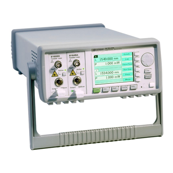
Numerical Keypad Power Key Softkeys Hardkeys Figure 7 The 8164A/B Lightwave Measurement System User Interface The 8163A/B and the 8166A/B do not provide the following two features of the 8164A/B’s user interface: • the Modify Knob, and • the Numerical Keypad. -
Page 39: Password
Tunable Laser modules, you must enter the password to unlock the instrument. The default password is 1234. NOTE If You Forget Your Password If you forget your password, contact your nearest Keysight Technologies Sales/Service Office. Find contact details by accessing http://www.keysight.com/ on the Internet. 8163A/B, 8164A/B, 8166A/B User’s Guide... -
Page 40: User Interface Features
Applications page -247, and • to identify a channel when using a GPIB command, see the 8163A/B Lightwave Multimeter, 8164A/B Lightwave Measurement System, & 8166A/B Lightwave Multichannel System Programming Guide for more information on GPIB commands. -
Page 41: How To Navigate/Modify The Display
-40 shows the overview screen for the 8163B Lightwave Multimeter, this screen is shown immediately after start-up. It shows the most important parameters of all installed modules. Figure 9 The 8163B’s Overview Screen 8163A/B, 8164A/B, 8166A/B User’s Guide... - Page 42 Getting Started The display of the Keysight 8163A and the Keysight 8166A is NOTE monochrome only. Figure 9 on page -40 shows the overview screen for the 8164A/B Lightwave Measurement System, this screen is shown immediately after start-up. It shows the most important parameters of all installed modules Figure 10 The 8164A/B’s Overview Screen...
- Page 43 -54, the up and down cursor keys can be used to increment and decrement the value of a digit and the left and right cursor keys can be used to move the highlighted digit left and right. 8163A/B, 8164A/B, 8166A/B User’s Guide...
- Page 44 Turning the Modify Knob anti-clockwise moves the highlighted marker left and then up. You can use the Modify Knob to change the value of a parameter. See to Change the Value of a Parameter on page -54. 8163A/B, 8164A/B, 8166A/B User’s Guide...
- Page 45 [Details] softkey. You should see the Details screen as shown in Figure on page -44, Figure 15 on page -45, or Figure 16 on page -46. Figure 14 The 8163B’s Details Screen for a Power Sensor Channel 8163A/B, 8164A/B, 8166A/B User’s Guide...
- Page 46 Getting Started Figure 15 The 8164A/B’s Details Screen for a Tunable Laser Channel 8163A/B, 8164A/B, 8166A/B User’s Guide...
- Page 47 Press the [Menu] softkey to access all the parameters and functions that apply to a module. Figure 17 on page -47 and Figure 19 on page -49 show the type of menu you should see for a Power Sensor channel. 8163A/B, 8164A/B, 8166A/B User’s Guide...
- Page 48 Getting Started Figure 17 The 8163B/6B Menu for a Power Sensor Channel 8163A/B, 8164A/B, 8166A/B User’s Guide...
- Page 49 Press the Config hardkey to access all the system configuration parameters that can be changed. Figure 19 on page -49 and Figure 20 page -50 show the menu you should see. See Additional Information page -61 for more details. 8163A/B, 8164A/B, 8166A/B User’s Guide...
- Page 50 Getting Started Figure 19 The 8163B System Configuration Menu 8163A/B, 8164A/B, 8166A/B User’s Guide...
- Page 51 Getting Started Figure 20 The 8164A/B System Configuration Menu How to Get Help Press the Help hardkey any time you need more information. The instrument displays online documentation for the currently selected parameter. 8163A/B, 8164A/B, 8166A/B User’s Guide...
- Page 52 Getting Started Figure 21 The 8164A/B Help Screen Press the [Index] softkey to access the Index of help topics. 8163A/B, 8164A/B, 8166A/B User’s Guide...
- Page 53 Press the [Print] softkey to print the current help page. See How to Connect a Printer on page -97 for more information on printing. Press the [Close] softkey to leave the online documentation and resume your task. 8163A/B, 8164A/B, 8166A/B User’s Guide...
- Page 54 Getting Started How to Access Applications You can access these applications for the Keysight 8163A/B Lightwave Multimeter or Keysight 8164A/B Lightwave Measurement System by pressing the Appl hardkey, the Applications Menu appears, as shown in Figure 23 on page -53. See Applications on page -247 for further details.
-
Page 55: How To Change The Value Of A Parameter
Details screen, after pressing the [Details] softkey, • from the Menu screen, after pressing the [Menu] softkey, or, • for the 8163A/B and 8164A/B, from the Overview screen. To start editing a parameter, you move to it and: • press the Enter hardkey, •... -
Page 56: How To Make A Small Change To A Continuous Parameter
Repeat steps 2 and 3 to continue editing the value. When you have finished editing the value, press Enter. The edited value becomes the new value of the parameter. 8163A/B, 8164A/B, 8166A/B User’s Guide... -
Page 57: How To Change A Discrete Parameter
Move to the Power Sensor channel and press the [Menu] softkey. Move to the <Averaging Time> parameter and press Enter. You see the screen in Figure 25 on page -57. Move to <1 s>, by using the cursor key, and press Enter. 8163A/B, 8164A/B, 8166A/B User’s Guide... -
Page 58: How To Set All Parameters To Their Default Values
If you press Enter or the [OK] softkey and the parameter changes to a different value, then you tried to enter a value outside the calibrated range. The new value is the nearest valid value to the value you entered. 8163A/B, 8164A/B, 8166A/B User’s Guide... -
Page 59: A Sample Session
This sample session shows you how to measure the power of a modulated signal at a single wavelength. The sample session is written for the 8163A/B Lightwave Multimeter or 8164A/B Lightwave Measurement System, the Keysight 81960A Tunable Laser module, and the Keysight 81634B Power Sensor. To perform the... - Page 60 Enter 1540.000 and press Enter. How to set the averaging time for the Power Sensor module: a Move to the measurement averaging time, [Tavg], and press Enter. b Move to <1 s>, using the cursor key, and press Enter. 8163A/B, 8164A/B, 8166A/B User’s Guide...
- Page 61 You should notice that the power reading is approximately half the value set on the Tunable Laser module. This is because the output is modulated by a square wave with a 50% duty cycle. 8163A/B, 8164A/B, 8166A/B User’s Guide...
-
Page 62: Additional Information
/ 95 How to Connect a Printer / 97 This chapter describes the system functions of the 8163A/B Lightwave Multimeter, the 8164A/B Lightwave Measurement System, and the 8166A/B Lightwave Multichannel System. Here you will find out how to set the configuration settings and how to connect an external monitor. -
Page 63: Using The System Utilities
Using the System Utilities Press the Config hardkey to access configuration information for your mainframe. You see the screens in Figure 27 on page 62 and Figure 28 page 63. Figure 27 The 8163B/6B Configuration Menu 8163A/B, 8164A/B, 8166A/B User’s Guide... -
Page 64: How To Set The Backlight
How to Set the Backlight The Backlight and menu option allows you to change the appearance of the screen. The Backlight menu option is supported by the 8163A/B and 8166A/B NOTE but not by the 8164A/B. 8163A/B, 8164A/B, 8166A/B User’s Guide... - Page 65 Entering a Backlight Value Enter an integer value between zero and one hundred in this box and press Enter. The Contrast can also be set for the 8163A and the 8166A models, but NOTE only these models, as follows: 8163A/B, 8164A/B, 8166A/B User’s Guide...
-
Page 66: How To Set The Date & Time
To set the date and time: Press the Config hardkey. Move to the <Date & Time> menu option and press Enter. You see a box, similar to Figure 30 on page 66, displaying the current date and time settings. 8163A/B, 8164A/B, 8166A/B User’s Guide... - Page 67 Edit the hour, minute, or second using the cursor key. Press [OK]. Perform steps step 6 step 7 again if the date is not fully correct. When the time and date are both correct, press [Close] to return to the configuration menu. 8163A/B, 8164A/B, 8166A/B User’s Guide...
-
Page 68: How To Lock/Unlock The High-Power Laser Sources
Enter and the instrument unlocks. The default password is 1234. NOTE To lock the instrument, perform the steps above, but in step 2 move to the <Lock> menu option in place of the <Unlock> menu option. 8163A/B, 8164A/B, 8166A/B User’s Guide... -
Page 69: How To Set The Trigger Configuration
To change the triggering mode: Press the Config hardkey. Move to the <Trigger> menu option and press Enter. You see a box displaying the available triggering modes. 8163A/B, 8164A/B, 8166A/B User’s Guide... -
Page 70: How To Configure Startup Applications
To configure startup applications: Press the Config hardkey. Move to the <Startup Applications> menu option and press Enter. Select the application you want to start up when the system is switched on. 8163A/B, 8164A/B, 8166A/B User’s Guide... -
Page 71: How To Configure Your Foot Pedal
335. To configure your Foot Pedal: Press the Config hardkey. Move to the <Foot pedal support> menu option and press Enter. You see a box displaying <On> and <Off>. Figure 33 Enabling/Disabling the Foot Panel 8163A/B, 8164A/B, 8166A/B User’s Guide... - Page 72 Move to <On> to enable the Foot Pedal or move to <Off> to disable the Foot Pedal. The 8163A, 8164A, and 8166A require FPGA version 1.5 or higher. The NOTE FPGA version number and date is displayed after you boot up the instrument.
-
Page 73: How To Set The Gpib Address
Enter an integer value between 0 and 30 into this box and press Enter. The address is set to this value. Avoid using 21 as the GPIB address because this number is often the NOTE controller’s default GPIB address. 8163A/B, 8164A/B, 8166A/B User’s Guide... -
Page 74: How To Configure Lan
Additional Information How to Configure LAN User Interface Some new entries have been added to the Configuration menu, which can be opened with the [Config] hard key: Figure 35 Configuration Menu 8163A/B, 8164A/B, 8166A/B User’s Guide... - Page 75 Use the cursor keys (or the modify knob on the 8164B) to select “Current LAN Settings” in the “Configuration Menu” and press the [OK] soft key to open a box displaying the currently used LAN settings. Figure 36 Configuration - Current LAN Settings 8163A/B, 8164A/B, 8166A/B User’s Guide...
- Page 76 DHCP server and differ from the values entered in the “Edit LAN Settings” dialog. The message box does not update automatically. To update the values, press the [Close] soft key then select “Current LAN Settings” again. Figure 37 Current LAN Settings 8163A/B, 8164A/B, 8166A/B User’s Guide...
- Page 77 Edit LAN Settings Use the cursor keys (or the modify knob on the 8164B) to select “Edit LAN Settings” in the “Configuration Menu”, then press the [OK] soft key. Figure 38 Configuration - Edit LAN Settings 8163A/B, 8164A/B, 8166A/B User’s Guide...
- Page 78 Additional Information Edit the IP Address Use the cursor keys (or the modify knob and the numeric keypad on the 8164B) to edit the IP address. Figure 39 LAN Settings - IP Address 8163A/B, 8164A/B, 8166A/B User’s Guide...
- Page 79 • [right] set all bits in the actual byte, jump one byte right, and set the first byte in it The modify knob on the 8164B works like the [up] and [down] buttons. Figure 40 LAN Settings - Subnet Mask 8163A/B, 8164A/B, 8166A/B User’s Guide...
- Page 80 Additional Information Edit the Default Gateway Use the cursor keys (or the modify knob and the numeric keypad on the 8164B) to s edit the IP address. Figure 41 LAN Settings - DGatw 8163A/B, 8164A/B, 8166A/B User’s Guide...
- Page 81 • The [OK] soft key is disabled until the value in the editor is valid. • If you try to enter a character which would create an invalid host name, the instrument beeps. • If enter an empty host name, the host name is reset to its default value. 8163A/B, 8164A/B, 8166A/B User’s Guide...
- Page 82 • Delete the last character using the [Delete] soft key. • The [OK] soft key is disabled until the value in the editor is valid. • If you try to enter a character which would create an invalid domain name, the instrument beeps. 8163A/B, 8164A/B, 8166A/B User’s Guide...
- Page 83 Figure 44 Configuration - DHCP Use the cursor keys (or the modify knob on the 8164B) to select • “Off” if you want to disable DHCP, or • “On” if you want to enable DHCP. 8163A/B, 8164A/B, 8166A/B User’s Guide...
- Page 84 Additional Information Figure 45 Enable/Disable - DHCP Press the [OK] soft key. 8163A/B, 8164A/B, 8166A/B User’s Guide...
- Page 85 Use the cursor keys (or the modify knob on the 8164B) to select “Show MAC Address” in the “Configuration Menu” and press the [OK] soft key to open a box displaying the network adapters MAC address. Figure 46 Configure - Show MAC Address 8163A/B, 8164A/B, 8166A/B User’s Guide...
- Page 86 Additional Information Figure 47 MAC Address 8163A/B, 8164A/B, 8166A/B User’s Guide...
- Page 87 If you have changed network parameters and want to apply them, use the cursor keys (or the modify knob on the 8164B) to select “Restart network” in the “Configuration Menu”, then press the [OK] soft key. Figure 48 Configuration - Restart Network 8163A/B, 8164A/B, 8166A/B User’s Guide...
-
Page 88: How To Set The Speed Of The Serial Interface
Move to the <Serial Interface> menu option and press Enter. You see a box displaying all the available line speeds in bps. Figure 49 Selecting a Baudrate for the Serial Interface Move to the Baudrate required and press Enter. 8163A/B, 8164A/B, 8166A/B User’s Guide... -
Page 89: How To Update A Module
Press the Config hardkey. Move to the <Module Update> menu option and press Enter. You see a box that displays Module Update mode as on. Press [OK] to start the Module Firmware Download process. 8163A/B, 8164A/B, 8166A/B User’s Guide... -
Page 90: How To Select The Printer Type
You can print out any of the following information: • a help screen, see How to Get Help on page 50, • data from an application, see Printing Application Measurement Results on page 307. 8163A/B, 8164A/B, 8166A/B User’s Guide... - Page 91 • <EPSON 8 pin>, you can use any printer that is compliant with Epson 8 pin printers. Figure 51 Selecting a Printer Type Move to your printer type and press Enter. You return to the configuration menu. 8163A/B, 8164A/B, 8166A/B User’s Guide...
-
Page 92: How To Change The Password
Enter. You see a box requesting you to enter the new password. Enter your new password. It should be 4 digits long. Press Enter. If You Forget Your Password If you forget your password, contact your nearest Keysight Technologies Sales/Service Office. Find contact details by accessing http://www.keysight.com/ on the Internet. - Page 93 Move to the module using the cursor key for which you require information. Press Enter. The part number, serial number, and firmware revision of the chosen module are displayed, as shown in Figure 53 on page 93. 8163A/B, 8164A/B, 8166A/B User’s Guide...
- Page 94 [Close] to return to the configuration menu. Depending on the date of production, manufacturer will be returned as NOTE Keysight Technologies, Agilent Technologies or HEWLETT-PACKARD. How to Get Information About the Mainframe on page 94 for information on mainframe identity strings.
-
Page 95: How To Get Information About The Mainframe
Press [Close] to return to the configuration menu. Depending on the date of production, manufacturer will be returned as NOTE Keysight Technologies, Agilent Technologies or HEWLETT-PACKARD. How to Get Information About Modules on page 91 for information on module identity strings. -
Page 96: How To Connect An External Monitor
You can connect a standard VGA monitor to the 8164A/B Lightwave Measurement System and the 8166B Lightwave Multichannel System. This is a useful feature for making presentations or for training courses. You cannot connect a monitor to the 8163A/B Lightwave Multimeter or NOTE 8166A Lightwave Multichannel system. - Page 97 Additional Information Refer to the user’s guide that came with your monitor, if necessary, to NOTE locate your monitor’s output and input ports. 8163A/B, 8164A/B, 8166A/B User’s Guide...
-
Page 98: How To Connect A Printer
You can then print out any of the following information: • a help screen, see How to Get Help on page 50, • data from an application, see Printing Application Measurement Results on page 307. 8163A/B, 8164A/B, 8166A/B User’s Guide... -
Page 100: Power Measurement
User Guide Power Measurement How to Measure Power / 100 This chapter describes how to use the 8163A/B Lightwave Multimeter, the 8164A/B Lightwave Measurement System, and the 8166A/B Lightwave Multichannel System to measure optical power using a Power Meter, that •... -
Page 101: How To Measure Power
Move to the Power Meter channel and press the [Menu] softkey. Move to <Number of Digits> option and press Enter. You will see the screen in Figure 56 on page -100. Figure 56 The Number of Digits Menu Move to 2 and press Enter. 8163A/B, 8164A/B, 8166A/B User’s Guide... -
Page 102: How To Set The Power Unit
Watts. Power, in units of dB, is measured relative to a particular reference power value. For information on selecting this reference value, see How to Input a Reference Level on page 103. 8163A/B, 8164A/B, 8166A/B User’s Guide... -
Page 103: How To Set The Calibration Offset
(dBm) = P (dBm) - CAL(dB) measured input Where, is the adjusted value of the signal read in dBm, measured is the input signal level in dBm, and input CALis the calibration offset in decibels (dB). 8163A/B, 8164A/B, 8166A/B User’s Guide... -
Page 104: How To Set The Reference Level
Move to the Power Meter channel and press the [Details] softkey. Move to the [Ref] parameter and press the [Power Unit] softkey. Move to <W> and press Enter twice. Change the units to mW using the [Unit+] and [Unit-] softkeys. Enter 10.000 and press Enter. 8163A/B, 8164A/B, 8166A/B User’s Guide... - Page 105 (dBm) - REF(dB) display measuredA measuredB Where: is the displayed relative power, display is the absolute power level (see How to Set the Calibration measuredA Offset on page 102) measured by the current Power Meter, and 8163A/B, 8164A/B, 8166A/B User’s Guide...
- Page 106 Enter. For example, in Figure 58 on page -105, you could choose 3.1 (for channel 3.1). Refer to Slot and Channel Numbers on page 39 for information on channel numbers. Figure 58 Referencing Another Channel 8163A/B, 8164A/B, 8166A/B User’s Guide...
-
Page 107: How To Set The Wavelength
Make sure that the optical input is not receiving any light. If you are using multi-mode fiber-optic cable, you must disconnect the cable and cover the input to the Power Meter to perform a zero. It is good practice to perform a zero before making any important measurements. 8163A/B, 8164A/B, 8166A/B User’s Guide... - Page 108 Move to the <Zero> option to zero the current power measurement channel or the <Zero All> option to zero all power measurement channels. You will see the screen shown in Figure 60 on page -108, this appears for around 30 seconds while zeroing is performed. 8163A/B, 8164A/B, 8166A/B User’s Guide...
- Page 109 • the Power Meter receives ambient light because the input connector is uncovered. Press Enter and start again at step 1. When the zeroing operation finishes, press the [Close] softkey to close the menu. 8163A/B, 8164A/B, 8166A/B User’s Guide...
-
Page 110: How To Choose The Range Mode
<Auto>, the auto-ranging mode, ensures that the result has a displayed value between 9% and 100% of full scale. The default state is for automatic ranging to be enabled. • <Manual>, which allows you to set a user-defined range. 8163A/B, 8164A/B, 8166A/B User’s Guide... -
Page 111: How To Set The Range
Move to <dBm>, by using the cursor key, and press Enter. Move to the [Range Mode] parameter and press Enter. Move to <Auto>, by using the cursor key, and press Enter. Perform a set of measurements. 8163A/B, 8164A/B, 8166A/B User’s Guide... - Page 112 Figure 64 on page -112, is shown. This means that the measured power is greater than the Upper Power Limit. You must decrease the [Range] value. Table 11 on page -114 for more details. 8163A/B, 8164A/B, 8166A/B User’s Guide...
- Page 113 Figure 65 on page -113, is shown. This means that the measured power is greater than the resolution at this [Range] value. You must increase the [Range] value. Table 11 on page -114 for more details. 8163A/B, 8164A/B, 8166A/B User’s Guide...
- Page 114 -114 shows an example of the range values you can choose for the Keysight 81634B. Inn this case the values range from 10 dBm (upper power limit of 13 dBm) to -70 dBm (upper power limit of -67 dBm) in 10 dBm increments. 8163A/B, 8164A/B, 8166A/B User’s Guide...
- Page 115 43.000 dBm 0.001 W -0.000 dBm 30 dBm 1.9999 W 33.000 dBm 0.1 mW -10.000 dBm 20 dBm 199.99 mW 23.000 dBm 0.01 mW -20.000 dBm 10 dBm 19.999 mW 13.000 dBm 0.001 mW -30.000 dBm 8163A/B, 8164A/B, 8166A/B User’s Guide...
-
Page 116: How To Set The Averaging Time
For averaging times of 1 second or less, a new measurement is shown at the end of each averaging time. This is drawn in Figure . A new measurement is shown on the display at each x. Measurement with Tavg ~1 second 8163A/B, 8164A/B, 8166A/B User’s Guide... -
Page 117: How To Choose The Minmax Mode
[Pmin], and the maximum value measured, [Pmax]. The difference between these values, P, is displayed in place of P, the power value. This mode is intended principally for polarization dependent measurements, but can be used for other types of measurement. 8163A/B, 8164A/B, 8166A/B User’s Guide... - Page 118 Time for display to update The length of the lines displayed represents the N Samples Refresh size of the buffer at the Mode time of update Time for display to update Figure 67 The Window and Refresh Modes 8163A/B, 8164A/B, 8166A/B User’s Guide...
-
Page 119: How To Turn Off Minmax Mode
To turn off MinMax mode, and return to continuous power measurement: Move to the Power Meter channel and press the [Details] softkey. Move to the [MinMax Mode] parameter and press Enter. Move to <Off>, by using the cursor key, and press Enter. 8163A/B, 8164A/B, 8166A/B User’s Guide... -
Page 120: How To Hold The Screen
By pressing the [Hold/Cnt] softkey a second time the screen will display new measurements continuously. How to Use Triggers Keysight 8163A/B Series Power Meter modules allow you trigger the instrument to perform tasks and to output trigger signals to external measurement instruments. - Page 121 Power Measurement How to Trigger Power Measurements You can configure 8163A/B Series Power Meter modules to perform certain tasks when you apply a trigger to the Input Trigger Connector. You must prearm a measurement function before an action can be...
- Page 122 :TRIGger GPIB command, see your mainframe’s Programming Guide. How to Use Output Triggering You can configure 8163A/B Series Power Meter modules to output a trigger when the instrument performs certain tasks. To set your module’s Output Trigger Configuration:...
-
Page 123: Dual Power Meters - Master And Slave Channels
-122 can only be set or viewed using the master channel. Table 12 Parameters that can only be set using the master channel Parameter <Zero> <MinMax mode> <Reset MinMax> <Data points> <Averaging time> <Range mode> <Input trigger mode> <Output trigger mode> 8163A/B, 8164A/B, 8166A/B User’s Guide... -
Page 124: Laser Sources
User’s Guide Laser Sources How to Use Laser Source Modules / 124 This chapter describes how to use the 8163A/B Lightwave Multimeter, the 8164A/B Lightwave Measurement System, and the 8166A/B Lightwave Multichannel System to control fixed wavelength laser source modules. -
Page 125: How To Use Laser Source Modules
To choose both output wavelengths for a dual-wavelength laser source module: λ Move to [ ] parameter and press Enter. Select <1309.6+1551.6>, using the cursor key, and press Enter. You will see the screen in Figure 73 on page -125. 8163A/B, 8164A/B, 8166A/B User’s Guide... -
Page 126: How To Enable/Disable Laser Output
To disable laser output using the user interface: Move to [State] parameter and press Enter. Move to [Off], by using the cursor key, and press Enter. The green LED on the module front panel switches off. 8163A/B, 8164A/B, 8166A/B User’s Guide... -
Page 127: How To Set Attenuation
Move to the laser source channel and press the [Details] softkey. You see the screen in Figure 74 on page -126. Figure 74 The Power Sensor Details Screen Move to the [Attenuation] parameter and press Enter. Enter 2.00 and press Enter. 8163A/B, 8164A/B, 8166A/B User’s Guide... -
Page 128: How To Modulate The Optical Output
The amplitude is set by the power parameter. This is the maximum output power of the output signal; at the minimum output power, no power is output. Output Power Figure 75 The Modulated Signal 8163A/B, 8164A/B, 8166A/B User’s Guide... - Page 129 How to Increase Linewidth You can use coherence control to increase the linewidth of the optical signal output from your 8163A/B Series Laser Source module. Enabling the coherence control increases the linewidth of the optical output signal to between 50 and 500 MHz (typically). Coherence control greatly reduces interference effects and therefore improves the power stability in sensitive test setups.
- Page 130 Move to <Coherence Ctrl.>, by using the cursor key, and press Enter. The text Mod is still displayed in the Laser Source channel. 10 Enable the laser output, by pressing the Active hardkey on the module’s front panel. 8163A/B, 8164A/B, 8166A/B User’s Guide...
-
Page 131: How To Use Triggers
How to Use Output Triggering You can configure the output trigger connector to output a TTL signal at the frequency of the internal modulation of a Keysight 8163A/B Series Laser Source module. To set your module’s Output Trigger Configuration:... - Page 132 <Disabled>, the output trigger mode is disabled. • <Modulation>, the output trigger connector outputs a TTL signal at the frequency of the internal modulation. This signal is output whether the laser is switched on or off. Press Enter. 8163A/B, 8164A/B, 8166A/B User’s Guide...
-
Page 134: Tunable Lasers
How to Use Triggers / 163 How to Use Auxiliary Functions / 167 This chapter explains how to control Tunable Laser modules from the user interface of the 8163A/B Lightwave Multimeter, the 8164A/B Lightwave Measurement System, and the 8166A/B Lightwave Multichannel System. -
Page 135: What Is A Tunable Laser
What is a Tunable Laser? A tunable laser is a laser source for which the wavelength can be varied through a specified range. The Keysight Technologies Tunable Laser modules also allow you to set the output power, and to choose between continuous wave or modulated power. - Page 136 • <Both (master:1)>, where both optical outputs can be enabled but only the output of the low SSE optical output can be regulated. 8163A/B, 8164A/B, 8166A/B User’s Guide...
- Page 137 Tunable Lasers Figure 77 Setting High Power parameters 8163A/B, 8164A/B, 8166A/B User’s Guide...
- Page 138 SSE optical output, flashes. How to Set the Optical Output Move to [Output] and press Enter. Move to your chosen optical output and press Enter. How to Enable the Optical Output Move to [State] and press Enter. 8163A/B, 8164A/B, 8166A/B User’s Guide...
- Page 139 Move to [Power Mode] and press Enter. b Move to <Manual Att.> and press Enter. The attenuation parameter, [Atten.], appears, see Figure 79 on page -139. Move to [Atten.], type 3.000, using the numerical keypad, and press Enter. 8163A/B, 8164A/B, 8166A/B User’s Guide...
-
Page 140: What Is Excessive Power
If the text ExP is displayed in a Tunable Laser channel, see Figure 80 page -140, you have set an output power level that is larger than the laser diode can produce at the selected wavelength. 8163A/B, 8164A/B, 8166A/B User’s Guide... -
Page 141: How To Set The Laser To The Dark Position
To enable/disable the dark position: Move to the Tunable Laser channel and press the [Menu] softkey. Move to the <Dark position> and press Enter. The Dark Position box appears. Move to one of the following menu items: 8163A/B, 8164A/B, 8166A/B User’s Guide... -
Page 142: The Analog Output
In <Manual Att.> Mode, the relationship between the power value, [P], and the voltage level is only proportional to the output power if the attenuation remains constant. The attenuator adds a constant offset to the voltage level. 8163A/B, 8164A/B, 8166A/B User’s Guide... - Page 143 [Close]. Attenuator If you want to you use the analog output signal and your Tunable Laser module has an attenuator installed, it is advisable to use <Manual Att.> Mode and choose a constant attenuation value. 8163A/B, 8164A/B, 8166A/B User’s Guide...
-
Page 144: How To Set The Wavelength
How to Set the Wavelength Directly You can set a constant wavelength. To set the wavelength to 1545.500 nm: Move to the Tunable Laser channel. Move to the wavelength parameter, [λ], and press Enter. Enter 1545.500 and press Enter. 8163A/B, 8164A/B, 8166A/B User’s Guide... -
Page 145: How To Set A Relative Wavelength
Move to <Wavelength Mode> in the menu and press Enter. A menu appears. Move to <Offset>, by using the cursor key, press Enter, and press Close. You see the screen in Figure 83 on page -145. 8163A/B, 8164A/B, 8166A/B User’s Guide... - Page 146 Enter 1570 and press Enter. Note how the frequency offset, [ f], changes as you change the value of Δ NOTE λ How to Set the Base Wavelength You cannot set < 0>, the base wavelength directly. λ NOTE 8163A/B, 8164A/B, 8166A/B User’s Guide...
- Page 147 Enter 1.000 and press Enter. The frequency offset, [ f], changes to Δ 1.000 THz. Note how the output wavelength, [ ], changes as you change the value of λ NOTE Δ 8163A/B, 8164A/B, 8166A/B User’s Guide...
-
Page 148: How To Perform A Wavelength Sweep
148. For a <Continuous> sweep, [Step] sets the wavelength interval between NOTE output triggers, if you have set <Output Trigger Mode> to <Step Finished>, see on page 165. How to Use Output Triggering 8163A/B, 8164A/B, 8166A/B User’s Guide... - Page 149 Start] and to end every sweep cycle at [ Stop]. Figure 85 on page -148 illustrates how these modes work for a three-cycle wavelength sweep. <Twoway> <Oneway> l Stop l Stop l Start l Start Figure 85 Repeat Modes 8163A/B, 8164A/B, 8166A/B User’s Guide...
-
Page 150: How To Perform A Sweep
Enter 3 and press Enter. 10 Move to [Repeat Mode] and press Enter. 11 Move to <Twoway>, by using the cursor key, and press Enter. 12 Move to [Step] and press Enter. 13 Enter 1.000 and press Enter. 8163A/B, 8164A/B, 8166A/B User’s Guide... - Page 151 Figure 87 page -151 appears. You can: • Press [Continue] to continue sweeping automatically. • Press [Prev] or [Next] to sweep manually. • Press [Stop] to end the sweep. Figure 86 Executing a Stepped Sweep 8163A/B, 8164A/B, 8166A/B User’s Guide...
- Page 152 Move to the Tunable Laser channel and press [Details]. Move to [Sweep Mode] and press Enter. Move to the <Continuous> sweep mode and press E NTER λ Move to [ Start] and press Enter. Enter 1520.000 and press Enter. 8163A/B, 8164A/B, 8166A/B User’s Guide...
- Page 153 The only allowed modulation source with the lambda logging function is Modulation = On AND coherence control. ModulationSource! = CoherenceControl 375,LambdaLogging = On AND lambda logging only works "Step Finished" output trigger configuration TriggerOut! = StepFinished 8163A/B, 8164A/B, 8166A/B User’s Guide...
- Page 154 -154 then appears. You can: • press [Next] to move on to the next wavelength step, • press [Prev] to move on to the previous wavelength step, or • press [Stop] to end the sweep. 8163A/B, 8164A/B, 8166A/B User’s Guide...
- Page 155 Tunable Lasers Figure 88 Performing a Manual Sweep Perform step 6 until you choose to press [Stop]. 8163A/B, 8164A/B, 8166A/B User’s Guide...
-
Page 156: How To Modulate A Signal
Enter. How to Set the Frequency of a Modulated Signal To set the frequency of the modulation to 6.500 kHz: Move to the frequency parameter, [Mod Frq], press Enter. Enter 6.500 press Enter. 8163A/B, 8164A/B, 8166A/B User’s Guide... -
Page 157: How To Use External Modulation
There is one BNC connector on the front panel of the 81689A and 819xxA compact tunable laser modules, a BNC input connector. An absolute maximum of ±6 V can be applied as an external voltage to any BNC connector. 8163A/B, 8164A/B, 8166A/B User’s Guide... - Page 158 There is one BNC connector on the front panel of the 81689A and 819xxA compact tunable laser modules, a BNC input connector. An absolute maximum of ±6 V can be applied as an external voltage to any BNC connector. 8163A/B, 8164A/B, 8166A/B User’s Guide...
- Page 159 There are two BNC connectors on the front panel of the 814xxB, 816xxB CAUTION and 8160xA tunable laser modules, a BNC input connector and a BNC output connector. An absolute maximum of ± 6 V can be applied as an external voltage to any BNC connector. 8163A/B, 8164A/B, 8166A/B User’s Guide...
- Page 160 A maximum of 5 V can be applied as an external voltage to the Input CAUTION Trigger connector. Take care not to use the Trigger Output connector or the Remote Interlock connector for modulation. Do not apply an external voltage to these connectors. 8163A/B, 8164A/B, 8166A/B User’s Guide...
- Page 161 Menu -> Modulation Frequency -> desired value Menu -> Output trigger mode -> Modulation Set all “slave” modules: Menu -> Modulation Source -> Backplane (new for DFB modules) Menu -> Output trigger mode -> disabled (important) 8163A/B, 8164A/B, 8166A/B User’s Guide...
-
Page 162: How To Configure The Modulation Output
Move to <BNC Output> and press [OK]. Move to <Modulation>, by using the cursor key. A TTL-level signal is output, if the optical output is digitally modulated, that is, if you choose <Internal>, <External Digital>, or <Backplane> as the chosen 8163A/B, 8164A/B, 8166A/B User’s Guide... - Page 163 • <FRQ>, where the modulation signal is output all the time regardless of laser state. Press [OK]. Press [Close] to return to the overview or detail screen. 8163A/B, 8164A/B, 8166A/B User’s Guide...
-
Page 164: How To Use Triggers
Move to the Tunable Laser channel and press [Menu]. Move to <Input Trigger Mode>, by using the cursor key, and press . You will see the screen in Figure 93 on page -164. NTER 8163A/B, 8164A/B, 8166A/B User’s Guide... - Page 165 Input Trigger Connector on the rear panel of your instrument, • setting <Trigger Configuration> to <Loopback> so that an output trigger automatically generates an input trigger, or • using the :TRIGger GPIB command, see your mainframe’s Programming Guide. 8163A/B, 8164A/B, 8166A/B User’s Guide...
-
Page 166: How To Use Output Triggering
This signal is output whether the laser is switched on or off. <Step Finished>, a trigger is output after every step of a sweep finishes. <Sweep Finished>, a trigger is output after a sweep cycle finishes. 8163A/B, 8164A/B, 8166A/B User’s Guide... - Page 167 <Sweep Started>, a trigger is output after a sweep cycle starts. Press Enter. If you choose <Step Finished> and a <Continuous> sweep, the NOTE wavelength interval between hard ware triggers is set by the [Step] parameter, although, the sweep is not stepped. 8163A/B, 8164A/B, 8166A/B User’s Guide...
-
Page 168: How To Use Auxiliary Functions
Move to <Realign> and press [OK]. You will see the screen in Figure 95 on page -168. Wait approximately 30 minutes. This time depends on how much the alignment of the instrument has drifted since the last Automatic Realignment was performed. 8163A/B, 8164A/B, 8166A/B User’s Guide... - Page 169 “UNCAL” is shown on the user interface in both Autocal modes. No Accuracy class is shown in the Autocal Off mode. The bit 6 “ARA recommended” is set in the “questionable condition register” (See the 8163A/B Lightwave Multimeter, 8164A/B Lightwave Measurement System, 8166A/B Lightwave Multichannel System Programming Guide) Please execute Realign in this case.
-
Page 170: How To Perform A Lambda Zero
To perform a wavelength zero: Move to the Tunable Laser channel and press Menu. λ Move to < Zeroing> and press [OK]. You will see the screen in Figure on page -170. 8163A/B, 8164A/B, 8166A/B User’s Guide... -
Page 171: Auto Cal Off
Lambda Zeroing temperature. In this case, the accuracy and wavelength performance of the TLS can become less optimal due to temperature variation. The relevant accuracy class is indicated on the user interface when Auto Calibration is off. 8163A/B, 8164A/B, 8166A/B User’s Guide... - Page 172 Lambda Zero before switching Auto Cal off. If Lambda Zero is recommended (Accuracy Class is not ACC1) the 10th NOTE bit of the “questionable condition register” is set (See the 8163A/B Lightwave Multimeter, 8164A/B Lightwave Measurement System, 8166A/B Lightwave Multichannel System Programming Guide). This is done in both Auto Cal On and Off.
- Page 173 Also no settling will occur during operation at a fixed wavelength when at least one output is switched on. By periodically checking the “questionable condition register” bit 10 you can detect when Lambda Zero is recommended. 8163A/B, 8164A/B, 8166A/B User’s Guide...
-
Page 174: Compact Tunable Lasers
Compact Tunable Laser modules / 174 How to Use a compact Tunable Laser / 175 This chapter explains how to use the 8163A/B Lightwave Multimeter, 8164A/B Lightwave Measurement System, or 8166A/B Lightwave Multichannel System together with the modular Keysight compact Tunable Laser family. -
Page 175: Compact Tunable Laser Modules
The 81960A, 81940A and 81949A cover the C and L bands, with high power in the L band. Each module covers a total wavelength range of 110 nm. The 81960A covers a range of 125 nm. 8163A/B, 8164A/B, 8166A/B User’s Guide... -
Page 176: How To Use A Compact Tunable Laser
• Set a value for the SBS suppression control frequency, SBSC frq, appropriate to your application. • Set a value for the SBS suppression control level, SBSC lvl, appropriate to your application. 8163A/B, 8164A/B, 8166A/B User’s Guide... - Page 177 Compact Tunable Lasers Figure 97 Updated Tunable Laser channel Details including SBS Suppression 8163A/B, 8164A/B, 8166A/B User’s Guide...
-
Page 178: Return Loss Measurement
Return Loss Measurement / 184 A Background to Return Loss Measurement / 203 This chapter explains how to use the 8163A/B Lightwave Multimeter, 8164A/B Lightwave Measurement System, or 8166A/B Lightwave Multichannel System to measure Return Loss. Here you will find: •... -
Page 179: Getting Started With Return Loss
It is a ratio of the power transmitted by the device to the power incident on the device. More normally we talk about the Insertion Loss of a component. The insertion loss has units of dB. Insertion Loss is given by: 8163A/B, 8164A/B, 8166A/B User’s Guide... -
Page 180: Equipment Required
Source physical contact patchcord Reflectivity 81113PC Figure 98 Measuring Return Loss and Insertion Loss To measure insertion loss you measure the power transmitted through the DUT, see How to Measure Return Loss on page 198. 8163A/B, 8164A/B, 8166A/B User’s Guide... -
Page 181: How To Choose A Light Source
If you use high-coherence light sources, you can improve performance NOTE • modulating the output signal at 2 kHz or higher, or • using coherence control to reduce the coherence length of the signal. 8163A/B, 8164A/B, 8166A/B User’s Guide... -
Page 182: Return Loss Modules
81610A Return Loss module The 81610A Return Loss Module includes a power sensor, monitor diode and two couplers in one module. It is for use in the 8163A/B Lightwave Multimeter, the 8164A/B Lightwave Measurement System, and the 8166A/B Lightwave Multichannel System for making return loss measurements. - Page 183 External Laser Source Internal Laser Sources Output 9/125 mm Figure 101 The Contents of the 81613A Return Loss modules All 8161x series Return Loss modules include an input for an external laser source. 8163A/B, 8164A/B, 8166A/B User’s Guide...
-
Page 184: Calibration Measurements
The Return Loss Application described later in the manual, available on the 8163B and 8163A, provides a convenient guide through the calibration and measurement process. 8163A/B, 8164A/B, 8166A/B User’s Guide... -
Page 185: Return Loss Measurement
-184 if you are using an External Source. 8161x Laser 8163B Lightwave Multimeter Source Figure 102 Return Loss Measurement Setup - External Source used Figure 103 on page -185 if you are using an internal source. 8163A/B, 8164A/B, 8166A/B User’s Guide... - Page 186 Use an averaging time of at least 200 ms, but increase this to at least 1 s for return losses greater than 50 dB. Longer averaging times give more accurate results, but reduce the speed at which the instrument can complete a measurement. 8163A/B, 8164A/B, 8166A/B User’s Guide...
- Page 187 T-value (system "noise") is subtracted from the power that corresponds to the measured return loss at the return loss diode, yielding the actual return loss. When the actual return loss is high, then this 8163A/B, 8164A/B, 8166A/B User’s Guide...
- Page 188 These parameters are made available using the "Show Calibration " menu item, or using the GPIB query: SENSe [n ]:[CHANnel [m ]]:RETurnloss:CALibration:VALUES? Figure 105 Reflectance Calibration using RL Reference 8163A/B, 8164A/B, 8166A/B User’s Guide...
-
Page 189: Calibrating The Return Loss Module
Reference Cable and mesurement patchcord. This is usually the preferred procedure for this reason. • These procedures are decribed in Calibration using the Keysight 81610CC Reference Cable on page 192. 8163A/B, 8164A/B, 8166A/B User’s Guide... -
Page 190: Calibration Using The Keysight 81000Br Reference Reflector
Keysight 81000BR Keysight 81000FI Figure 108 Reflection Calibration - Internal Source Tip: For best results and higher repeatability, fix the cable. Attach a component with a known return loss to the end of the patchcord. 8163A/B, 8164A/B, 8166A/B User’s Guide... - Page 191 The [RL] value changes to the same value as entered for [RLref]. step 7 Tip: An alternative step is to select the Return Loss module’s [Detail] screen, then press [RefCal] 8163A/B, 8164A/B, 8166A/B User’s Guide...
- Page 192 Termination Calibration - Internal Source If you are using an external source, you must fix its output cable to NOTE ensure minimum cable movement. Terminate the cable so that there are no reflections coming from the end. 8163A/B, 8164A/B, 8166A/B User’s Guide...
-
Page 193: Calibration Using The Keysight 81610Cc Reference Cable
8161x Laser 8163B Lightwave Multimeter Source Keysight 81610CC Reference Cable Figure 112 Measuring the Return Loss of the Reference Cable - External Source Figure 113 on page -193 if you are using an internal source. 8163A/B, 8164A/B, 8166A/B User’s Guide... - Page 194 Delta. This is the difference between the insertion loss of the reference cable, and the insertion loss of the patchcord used for return loss measurement. The difference is normally the difference in the front panel connection, which can change with each reconnection. 8163A/B, 8164A/B, 8166A/B User’s Guide...
- Page 195 Move to <Pwr unit>, move to <dB> and press Enter. • Move to <Display to Reference> and press Enter. This sets the power transmitted through the reference cable, E , as the reference Meas value <Ref>. 8163A/B, 8164A/B, 8166A/B User’s Guide...
- Page 196 If necessary, move to <Pwr unit>, move to <dB> and press Enter. • The Power Sensor channel displays a power value in dB that is equal to the front panel delta of the measurement system. 8163A/B, 8164A/B, 8166A/B User’s Guide...
- Page 197 Figure 118 Measuring the Termination Parameter - External Source Figure 119 on page -196if you are using an internal source. 8163B Lightwave Multimeter 8161x Termination measurement patchcord Figure 119 Measuring the Termination Parameter - Internal Source 8163A/B, 8164A/B, 8166A/B User’s Guide...
- Page 198 (or some similar object with a diameter of between 5 mm and 7 mm). Move to [Terminated calibration] and press Enter. The instrument measures the power reflected by the component, and sets the [Para] values used by the Return Loss monitor’s power sensor and monitor diode. 8163A/B, 8164A/B, 8166A/B User’s Guide...
-
Page 199: How To Measure Return Loss
Measuring the Return Loss of the DUT (in this example: a Connector Pair) Tip: Terminate your system close to the DUT to make sure that you are only measuring reflections from the DUT. Figure 121 Measuring the Power Transmitted through the DUT (a Connector Pair) 8163A/B, 8164A/B, 8166A/B User’s Guide... -
Page 200: Viewing The Calibration Values
• [Ref], the power measured by the Return loss Module’s internal power sensor during the reflectance calibration in dBm • [Meas], the power currently measured by the Return loss Module’s internal power sensor in dBm 8163A/B, 8164A/B, 8166A/B User’s Guide... - Page 201 • [Ref], the power measured by the Return Loss module’s monitor diode during the reflectance calibration in dBm • [Meas], the power currently measured by the Return loss Module’s internal monitor diode in dBm 8163A/B, 8164A/B, 8166A/B User’s Guide...
- Page 202 • [RLref] the value of the return loss of the reference relector used. If you areusing a reference cable, this value will be around 14.6 dB 8163A/B, 8164A/B, 8166A/B User’s Guide...
- Page 203 Return Loss Measurement Figure 124 The Calibration Parameters Screens - User Data 8163A/B, 8164A/B, 8166A/B User’s Guide...
-
Page 204: A Background To Return Loss Measurement
You can only measure the Front Panel Delta if you use a Reflection NOTE Reference Cable. The reflection factor for the component is called R . Normally the return loss for the component (RL ) is specified, but these values are related: 8163A/B, 8164A/B, 8166A/B User’s Guide... -
Page 205: Reference
. You can use E to calculate the front panel delta, see Calculating the Front Panel Delta on page 209. Keysight 81610A Reflection Reference Power Meter Reference Cable Figure 126 Measuring the Power transmitted through the Reflection Reference 8163A/B, 8164A/B, 8166A/B User’s Guide... -
Page 206: Measuring The Power When There Are No Reflections
209 and to calculate the insertion loss, see Calculating the Insertion Loss of the DUT page 211. Keysight 81610A Reflection Reference Power Meter Meas measurement patchcord Figure 128 Measuring the Power transmitted through the Measurement Patchcord 8163A/B, 8164A/B, 8166A/B User’s Guide... -
Page 207: Measuring The Reflections From The Dut
Power Meter patchcord Reflectivity Figure 130 Measuring the Power transmitted through the Device Under Test You can use E to calculate the insertion loss, see Calculating the Insertion Loss of the DUT on page 211. 8163A/B, 8164A/B, 8166A/B User’s Guide... -
Page 208: Calculating The Return Loss Of The Dut
Output port, k times that power is output at the sensor port. It is not necessary to know the value for these constants, they can be eliminated later. 8163A/B, 8164A/B, 8166A/B User’s Guide... - Page 209 If we substitute equation 3 into equations 2 and 4, this gives us the following two equations: -------------- - P para para -------------- - P para para If we subtract P from equations 5 and 6, this gives us the following para equations: 8163A/B, 8164A/B, 8166A/B User’s Guide...
-
Page 210: Calculating The Front Panel Delta
Reflection Reference on page 204, and the power transmitted through the measurement cable, see Measuring the Power Transmitted Through the Measurement Patchcord on page 205. The system may be represented Figure 131 on page -210: 8163A/B, 8164A/B, 8166A/B User’s Guide... - Page 211 If we divide equation 11 by equation 12, this gives the following equation: (15) -------------- - ------------- - Meas Meas The loss variation, ΔL, due to exchanging the reference cable for the measurement cable is given by: (16) 8163A/B, 8164A/B, 8166A/B User’s Guide...
-
Page 212: Calculating The Insertion Loss Of The Dut
Through the Measurement Patchcord on page 205 and the power transmitted through the DUT, see Measuring the Power Transmitted Through the DUT on page 206. The equation below gives the insertion loss of the DUT, IL (18) 8163A/B, 8164A/B, 8166A/B User’s Guide... -
Page 214: Setting Attenuation And/Or Power Levels
/ 214 How to Use a Variable Optical Attenuator module / 216 This chapter explains how to use the 8163A/B Lightwave Multimeter, 8164A/B Lightwave Measurement System, or 8166A/B Lightwave Multichannel System together with the 8157xA family of Variable Optical Attenuator modules to attenuate and control optical power in single-mode optical fibers. -
Page 215: Keysight 8157Xa Variable Optical Attenuator Modules
Figure 132 on page -215 shows how a signal from a photo-diode after a monitor coupler is used as an active feedback loop 8163A/B, 8164A/B, 8166A/B User’s Guide... - Page 216 Setting Attenuation and/or Power Levels Figure 132 81576A/77A Attenuator module power control loop 8163A/B, 8164A/B, 8166A/B User’s Guide...
-
Page 217: How To Use A Variable Optical Attenuator Module
-216 is an Overview screen taken from an 8164A/B mainframe. Figure 133 81570A/71A/73A Attenuator module, 8164A/B GUI Overview Here: • Slot 1 hosts a tunable laser, • Slot 2 hosts an 81570A/71A/73A Attenuator module, • Slot 4 hosts a reference powermeter. 8163A/B, 8164A/B, 8166A/B User’s Guide... - Page 218 The Attenuator Details Display To display the full user interface for the Attenuator module, as shown in Figure 134 on page -218, use the Cursor key to highlight the Attenuator slot, then press the [Details] softkey: 8163A/B, 8164A/B, 8166A/B User’s Guide...
- Page 219 81570A/71A/73A Attenuator module, 8164A/B GUI Details Screen Elements All the figures in this chapter are taken from an 8164A/B mainframe. The user interface for an 8163A, 8163B, 8166A or 8166B mainframe may display fewer elements. Use the equivalent menu selection instead. Number of Digits displayed To select the number of significant decimal places displayed: Press the [Menu] softkey.
-
Page 220: How To Control The Shutter
The Attenuator module’s shutter state is protected by mainframe’s Remote Interlock (RIL) feature. The shutter cannot be opened if the 50W resistor is removed from the RIL connector on the back panel of the mainframe. See The Remote Interlock (RIL) connector on page 337. 8163A/B, 8164A/B, 8166A/B User’s Guide... -
Page 221: How To Set Attenuation
If the source is a multi-wavelength DWDM signal, set the Attenuator module to the weighted wavelength of the spectrum. α Figure 135 on page -220 shows an attenuation factor of 4.000 dB applied to a 1550nm source. Figure 135 Attenuation factor set to 4.000 dB 8163A/B, 8164A/B, 8166A/B User’s Guide... - Page 222 <Averaging Time>. Use a patchcord to connect the source output to the reference powermeter. Press the powermeter’s [Disp -> Ref] softkey. Power is now measured relative to this reference value, so the powermeter displays 0.000 dB 8163A/B, 8164A/B, 8166A/B User’s Guide...
- Page 223 11 Disconnect the patchcord from the reference powermeter and connect it to the DUT input. Figure 136 81570A/71A/73A - Attenuation factor applied with no offset α Figure 136 on page -222 shows an attenuation factor of 3.850 dB α applied with no Offset 8163A/B, 8164A/B, 8166A/B User’s Guide...
-
Page 224: Calibrating Test Setups That Use An 81570A/71A/73A/78A
These functions are mathematically identical. Neither function is a measurement of total intrinsic insertion loss as described in 81570A/71A/73A/78A modules on page 221, since the insertion loss of the Attenuator module itself is not included. 8163A/B, 8164A/B, 8166A/B User’s Guide... -
Page 225: How To Set A Power Level
Attenuator. Application Note. Keysight Technologies publication number 5988-5260EN. • 8163A/B Lightwave Multimeter, 8164A/B Lightwave Measurement System, and 8166A/B Lightwave Multichannel System, Programming Guide, part number 08164-90B65 (or a later edition). For accurate power measurements, the simple weighted wavelength of a NOTE multi-wavelength DWDM signal is insufficient. -
Page 226: Attenuator Module
Press the [PM-> ref ] softkey, • Select the channel used to host your reference powermeter, • Press [OK]. The power value measured by your reference powermeter is copied to the Attenuator and stored as P 8163A/B, 8164A/B, 8166A/B User’s Guide... - Page 227 It is good practice to zero the powermeters in your test setup . Refer to Hosting a Reference Powermeter on page 217. • To zero the powermeter incorporated in the Attenuator module, press [Menu] , then select <Zero>. 8163A/B, 8164A/B, 8166A/B User’s Guide...
- Page 228 If the reference powermeter is hosted by the same mainframe as the Attenuator module: • Select the P field, Offset • Press the [PM-> Off ] softkey, • Select the channel used to host your reference powermeter, • Press [OK]. 8163A/B, 8164A/B, 8166A/B User’s Guide...
- Page 229 Edit the P parameter to control the absolute power applied to the α DUT. The attenuation, , displayed is updated to reflect the new P value. Figure 138 81576A/77A Setting P after calibration using [PM->Off] 8163A/B, 8164A/B, 8166A/B User’s Guide...
-
Page 230: How To Compensate For Wavelength Dependencies In Your Test Setup
λ)] [Offset ( parameter. λ Ed iting the Offset Table If you have previously characterized the output path: Press the [Menu] softkey. λ Set <Offset ( ) > to <off >. 8163A/B, 8164A/B, 8166A/B User’s Guide... - Page 231 For an 8164A/B mainframe, the first three Offset Table entries are displayed. λ • For an 8163A/B mainframe, or an 8166A/B mainframe, the first Offset Table entry is displayed. If there are no entries, the message “Offset Table is Empty” is displayed. λ Figure 139 Offset Table λ...
-
Page 232: How To Construct A Λ Offset Table
The difference between the power measured by the Attenuator module’s integrated powermeter and that measured by the reference powermeter is λ stored in the Offset Table as a wavelength:Offset pair. λ Press [OK] to store the result in the Offset Table. Press [Close]. 8163A/B, 8164A/B, 8166A/B User’s Guide... - Page 233 If the operating wavelength is greater than, or less than, the range of λ wavelengths stored in the Offset Table, the offset value for the closest wavelength is extrapolated. The Attenuator status display includes ‘Ext’. 8163A/B, 8164A/B, 8166A/B User’s Guide...
-
Page 234: How To Use The Power Control Feature
When Power Control is On the Attenuator’s status display includes ‘PC’. The Menu item <Pwr Control> is functionally equivalent to the [Pwr Control] parameter. Attenuator Menu Options 81570A/71A/73A Menu Options Press the [Menu] softkey to display the window shown in Figure 141 page -234. 8163A/B, 8164A/B, 8166A/B User’s Guide... - Page 235 Setting Attenuation and/or Power Levels Figure 141 81570A/71A/73A Attenuator Menu Options 81576A/77A Menu Options Press the [Menu] softkey to display the window shown in Figure 142 page -235: 8163A/B, 8164A/B, 8166A/B User’s Guide...
- Page 236 The <P actual>, <Averaging Time>, <Zero>, <Zero all >, and <Input trigger mode> options are associated with the Attenuator’s integrated powermeter. • For more information about the <Input trigger mode> option, refer to How to Use Triggers on page 119. 8163A/B, 8164A/B, 8166A/B User’s Guide...
-
Page 237: Attenuator Status Indicators
There is either too much, or too little, input power for the (81566A/67A/76A/ 77A Attenuator module to set or maintain your desired P only) The Remote Interlock Connector of your mainframe is open. No measurement is possible until the connection at the Remote Interlock Connector closes. 8163A/B, 8164A/B, 8166A/B User’s Guide... -
Page 238: Switching Optical Routes
/ 240 Typical Applications / 244 This chapter explains how to use the 8163A/B Lightwave Multimeter, 8164A/B Lightwave Measurement System, or 8166A/B Lightwave Multichannel System together with the 8159xB family of Optical Switch modules to change optical routes during a test without having to disconnect and reconnect fibers. -
Page 239: Keysight 8159Xb Optical Switch Modules
Description 81591B Optical Switch, 1x2 81594B Optical Switch, 2x2 non-blocking (crossover) 81595B Optical Switch, 1x4 Options Option 009: Single-mode 9/125 µm, fixed FC/APC connector interfaces. Option 062: Multimode 50 (62.5)/125 µm, fixed FC/PC connector interfaces. 8163A/B, 8164A/B, 8166A/B User’s Guide... - Page 240 Switching Optical Routes Figure 143 Keysight 81595B Optical Switch module ( 1x4, angled contact connectors) 8163A/B, 8164A/B, 8166A/B User’s Guide...
-
Page 241: How To Use An Optical Switch Module
Optical Switch module, User Interface Overview display Here: • Slot 0 hosts a backloadable tunable laser, • Slot 1 hosts a Keysight 81594B 2x2 non-blocking (crossover) switch, • Slot 2 hosts a return loss module. 8163A/B, 8164A/B, 8166A/B User’s Guide... - Page 242 Optical Switch module, 8164A/B User Interface Details Screen Elements All the figures in this chapter are taken from an 8164A/B mainframe. The user interface for an 8163A, 8163B, 8166A or 8163B mainframe may differ in detail but the available functionality is identical. Configuration The Optical Switch configuration is indicated at the top left of the user interface.
-
Page 243: Dependent And Independent Routing
To switch the route between port A and another numbered port: Use the Cursor key to highlight [Route A <->], then press Enter. Use the Cursor key to enter the number of the port required. 8163A/B, 8164A/B, 8166A/B User’s Guide... -
Page 244: How To Set Route B
Optical Switch module. The route selected between port B, if present, and another numbered port is indicated in the user interface, and by two lit amber LEDs on the front panel of the Optical Switch module. 8163A/B, 8164A/B, 8166A/B User’s Guide... -
Page 245: Typical Applications
Figure 147 on page -244, a 81591B 1x2 Optical Switch is used to select between the measurement path and the calibration path. measurement and analysis Source equipment Power Meter automated control Figure 147 Measurement Path selection 8163A/B, 8164A/B, 8166A/B User’s Guide... -
Page 246: Inserting Or Bypassing An Optical Component
Selecting one of several DUTs in a parallel test setup Figure 149 on page -246, two 81595B 1x4 Optical Switches are used to select one of up to four DUTs in a parallel test setup 8163A/B, 8164A/B, 8166A/B User’s Guide... -
Page 247: Selecting One Of Several Instruments
1 x 4 switch Power meter Source BERT Figure 150 Test instruments selection In each case, the advantages to be gained from using switch modules include speedier changes to the test setup, and improved measurement repeatability. 8163A/B, 8164A/B, 8166A/B User’s Guide... -
Page 248: Applications
/ 303 Recording Measurement Results / 307 This chapter explains how to set up and perform the following applications using the 8163A/B Lightwave Multimeter or 8164A/B Lightwave Measurement System: • The Logging application logs and displays power measurements. The Logging application performs measurements consecutively without the possibility of any pause between measurements. - Page 249 You can access these applications by pressing the Appl hardkey. After you exit from the application, any modules that were available for NOTE use by these applications will automatically be preset, all parameters will be set to their default values. 8163A/B, 8164A/B, 8166A/B User’s Guide...
-
Page 250: Working With Application Graphs
The power values of C and D are displayed at the bottom of the screen in Δ the chosen power units. The symbol that is listed directly beneath these values, displays the difference between C and D in the chosen power units. 8163A/B, 8164A/B, 8166A/B User’s Guide... -
Page 251: How To Set Markers
You can also zoom in between markers: Set each marker as described above in Figure How to Set Markers page 250. Press the [Zoom In Betw] softkey to zoom in between the markers. 8163A/B, 8164A/B, 8166A/B User’s Guide... -
Page 252: How To Zoom Out
Legend numbers can be related to the curves they represent in the following ways: • For the 8163A/B Lightwave Multimeter the legend number is displayed at the same height as the first sample of the power measurement channel on the right-hand side of the screen. - Page 253 The Graph Legend Screen Move to the legend number you wish to edit using the cursor keys and press Enter. The on-screen keyboard appears. Use the on-screen keyboard to edit the legend label and press Enter. 8163A/B, 8164A/B, 8166A/B User’s Guide...
-
Page 254: How To Select The Samples Display
Press the [Menu] softkey and move to <Samples Display>. A box displaying the following options appears: • <Line> - the curve will be displayed using a line that connects between each sample of the curve. 8163A/B, 8164A/B, 8166A/B User’s Guide... - Page 255 <Samples> - the curve will be displayed using dots to represent each sample of the curve. Depending on the zoom level you choose, if these dots are very close to each other, the curve will resemble a line. 8163A/B, 8164A/B, 8166A/B User’s Guide...
- Page 256 Applications Figure 154 Samples Display - <Samples> • <Samples & Line> - the curve will be displayed using both symbols for each sample of the curve and a line connecting each sample. 8163A/B, 8164A/B, 8166A/B User’s Guide...
-
Page 257: How To Read Curve Values
You can lock markers A or B to a curve in order to move between individual samples. In this way, you can read the time/wavelength and power values that relate to each sample and the difference between these values for markers A and B. 8163A/B, 8164A/B, 8166A/B User’s Guide... - Page 258 If you want to assign marker B to another curve, press the [B] softkey, use the cursor key to move to the legend number of the curve to which you want to lock marker B, and press Enter. 8163A/B, 8164A/B, 8166A/B User’s Guide...
- Page 259 Figure 157 on page -258shows a graph where markers A and B are locked to samples. If you press the cursor key, the marker will move to another sample. Figure 157 Lock to Samples On 8163A/B, 8164A/B, 8166A/B User’s Guide...
- Page 260 To lock/unlock markers to samples: Press the [Menu] softkey. Move to one of the following menu items: • <Lock to Samples On>, to lock markers to samples or • <Lock to Samples Off>, to lock markers to the curve. 8163A/B, 8164A/B, 8166A/B User’s Guide...
- Page 261 Applications Only one of these menu items will be available for selection. NOTE Press Enter to return to the graph. 8163A/B, 8164A/B, 8166A/B User’s Guide...
-
Page 262: The Logging Application
274 because all power measurements are performed consecutively without the possibility of any pause between measurements, as shown in Figure 159 on page -261. All results can be: • displayed on the screen, • printed out to hardcopy. 8163A/B, 8164A/B, 8166A/B User’s Guide... -
Page 263: How To Set Up A Logging Function
The Applications Menu Move to <Logging> and press Enter. The 8164A/B Logging Setup Screen, as shown in Figure 161 on page -263, or the 8163A/B Logging Modules Setup Screen, as shown in Figure 162 on page -264, appears depending on the mainframe instrument you are using. - Page 264 Applications Figure 161 The 8164A/B Logging Setup Screen 8163A/B, 8164A/B, 8166A/B User’s Guide...
- Page 265 39, press [Set]. Perform steps until you have selected the required Power Meters for your application and press Enter. If no Power Meter channel is selected, you cannot ‘exit’ by pressing NOTE Enter. 8163A/B, 8164A/B, 8166A/B User’s Guide...
- Page 266 NOTE Power meter parameters from the Logging Setup Screen, see Figure 161 on page -263. If you are using the 8163A/B Lightwave Multimeter, press [Parameter] to NOTE access the Logging Parameter Setup Screen, as shown in Figure 163 page -265. To return to the Logging Modules Setup Screen, press [Modules].
- Page 267 Logging Setup screen, move to [Range], press the [Edit] softkey. Move to <Ref Mode>, press Enter, move to one of the following referencing modes: step 8 • <Value>, you set a reference value using <Ref>, see 8163A/B, 8164A/B, 8166A/B User’s Guide...
-
Page 268: Running A Logging Application
A progress bar shows the proportion of the logging application that has been completed. If the averaging time [AvgTime] is less than 100 ms for a 8163xA/B series NOTE powermeter, the progress bar and the graph are not updated until the measurement completes. 8163A/B, 8164A/B, 8166A/B User’s Guide... - Page 269 When the logging application completes, you hear a beep, an hourglass appears momentarily. If you are viewing the Logging Measurement Screen the available softkeys change as shown in Figure on page -269. 8163A/B, 8164A/B, 8166A/B User’s Guide...
-
Page 270: Analysing A Logging Application
You cannot access the Logging Analysis screen from the graph. If you are viewing the graph, press [Close]. Press [Analysis]. The Logging Analysis screen appears as shown in Figure 166 on page -270 for the 8164A/B and Figure 163for the Keysight 8163B. 8163A/B, 8164A/B, 8166A/B User’s Guide... - Page 271 Applications Figure 166 The 8164A/B Logging Analysis Screen 8163A/B, 8164A/B, 8166A/B User’s Guide...
- Page 272 (thus, each data value for channel 1 will be 0 dB), and • press Enter. These settings have an effect when you choose <dB> as the <Pwr unit>. NOTE See step 2 or step 3. 8163A/B, 8164A/B, 8166A/B User’s Guide...
- Page 273 If you are using the 8164A/B, move to [Stat Ch.], press Enter, move to a Power Meter channel, and press Enter. If you are using the 8163A/B, press [More], the screen in Figure 168 page -272 appears, move to [Stat Ch.], press Enter, move to a Power Meter channel, and press Enter.
-
Page 274: On-Screen Messages
Optical Head channel as a power measurement channel. No Data No data has been measured or measurement is not yet finished. You cannot access the Analysis Screen yet. Printout and file operations are not yet possible. 8163A/B, 8164A/B, 8166A/B User’s Guide... -
Page 275: The Stability Application
• the averaging time is less than 100 ms. • The averaging time is equal to the period time, all power measurement are performed without any dwell time. 8163A/B, 8164A/B, 8166A/B User’s Guide... -
Page 276: How To Set Up A Stability Function
To set up a stability function: Press the Appl hardkey. The Applications menu, as shown in Figure 160 on page -262, appears. Move to <Stability> and press Enter. The Stability Setup Screen, as shown Figure 170 on page -276, appears. 8163A/B, 8164A/B, 8166A/B User’s Guide... - Page 277 Applications Figure 170 The Keysight 8164A/B Stability Setup Screen 8163A/B, 8164A/B, 8166A/B User’s Guide...
- Page 278 39, press [Set]. Perform steps until you have selected the required Power Meters for your application and press Enter. If no Power Meter channel is selected, you cannot exit by pressing Enter. NOTE 8163A/B, 8164A/B, 8166A/B User’s Guide...
- Page 279 Move to <Pwr unit>, press Enter, move to <dBm>, <W>, or <dB>, and press Enter. See What are the Power Units ? on page 101 for an explanation of power units. Move to <λ>, press Enter, enter the wavelength value of your optical source, and press Enter. 8163A/B, 8164A/B, 8166A/B User’s Guide...
- Page 280 <Channel 1>, the value that Channel 1 measures is updated as the reference value for each set of power measurements (thus, each data value for channel 1 will be 0 dB), and • press Enter. 8163A/B, 8164A/B, 8166A/B User’s Guide...
- Page 281 17 You can run the stability application by pressing [Measure]. The Stability Measurement screen, as shown in Figure 173 on page -281, appears. A progress bar shows the proportion of the stability application that has been completed. 8163A/B, 8164A/B, 8166A/B User’s Guide...
- Page 282 19 When the stability application completes, you hear a beep, an hourglass appears momentarily. If you are viewing the Stability Measurement Screen, the available softkeys change as shown in Figure on page -281. 8163A/B, 8164A/B, 8166A/B User’s Guide...
-
Page 283: Analysing A Stability Application
20 You cannot access the Stability Analysis screen from the graph. If you are viewing the graph, press [Close]. 21 Press [Analysis]. The Stability Analysis screen appears as shown in Figure 175 on page -283 for the Keysight 8164A/B and Figure 175 page -283for the Keysight 8163B. 8163A/B, 8164A/B, 8166A/B User’s Guide... - Page 284 Applications Figure 175 The Keysight 8164A/B Stability Analysis Screen 8163A/B, 8164A/B, 8166A/B User’s Guide...
- Page 285 (thus, each data value for channel 1 will be 0 dB), and • press Enter. These settings have an effect when you choose <dB> as the <Pwr unit>. NOTE See step 7 or step 22. 8163A/B, 8164A/B, 8166A/B User’s Guide...
- Page 286 25 If you are using the Keysight 8164A/B, move to [Stat Ch.], press Enter, move to a Power Meter channel, and press Enter. If you are using the Keysight 8163A/B, press [More], a screen similar to that shown in Figure 177 on page -285appears, move to [Stat Ch.], press...
-
Page 287: On-Screen Messages
Optical Head channel as a power measurement channel. No Data No data has been measured or measurement is not yet finished. You cannot access the Analysis Screen yet. Printout and file operations are not yet possible. 8163A/B, 8164A/B, 8166A/B User’s Guide... -
Page 288: The Pact Application
System to control a system for testing pigtailed or connectorized passive devices (filters, couplers, and isolators) over wavelength. You must first install a Tunable Laser module and Power Meters in your 8163A/B Lightwave Multimeter or 8164A/B Lightwave Measurement System. Depending on the configuration of the system you use, you can measure insertion loss (single channel power measurement) over wavelength. - Page 289 If no Tunable Laser module is selected, you cannot exit by pressing Enter. NOTE PACT is not available for 81606A, 81607A, 81608A and 81609A. Instead use the free N7700A IL Engine software for a PC. 8163A/B, 8164A/B, 8166A/B User’s Guide...
- Page 290 Enter. The instrument chooses a constant power level for the measurement using the following constraints: • the power will be less than or equal to the [P max] value you set and 8163A/B, 8164A/B, 8166A/B User’s Guide...
- Page 291 • Press Enter. 17 If your Tunable Laser module has two optical outputs perform the step below. Move to [Optical Output] and press Enter. Use the Modify Knob to move to one of the following: 8163A/B, 8164A/B, 8166A/B User’s Guide...
-
Page 292: How To Measure The Reference
-292, appears. The number of samples that each Power Meter will record and the output laser power are displayed If <Continuous> was selected as the sweep [Method], the sweep speed, [V Sweep], is displayed. 8163A/B, 8164A/B, 8166A/B User’s Guide... - Page 293 The application chooses the power, [P], see step 14 for more NOTE information. 19 Press [New Ref]. A box similar to the box in Figure 180 on page -293 appears prompting you to connect a fiber to the first Power Meter channel. 8163A/B, 8164A/B, 8166A/B User’s Guide...
- Page 294 Press [Cancel] to return to the PACT Reference screen without completing the reference measurement, all reference values that were measured will be deleted. 22 When the PACT Reference Measurement completes, you hear a beep, an hourglass appears momentarily. 8163A/B, 8164A/B, 8166A/B User’s Guide...
-
Page 295: How To Perform A Loss Measurement
PACT Reference Measurement Finished Box How to Perform a Loss Measurement 23 To return to the Setup screen, pressing [Menu], move to <Setup>, and press Enter. If you change any measurement parameters, the reference measurement NOTE becomes invalid. 8163A/B, 8164A/B, 8166A/B User’s Guide... - Page 296 The number of samples that each Power Meter will record and the output laser power are displayed. If <Continuous> was selected as the sweep [Method], the sweep speed, [V Sweep], is displayed. Figure 182 PACT Measurement Screen 8163A/B, 8164A/B, 8166A/B User’s Guide...
- Page 297 -87 shows a graph Figure 49 with high dynamic range that is the result of a three sweeps that were combined using a "stitching" process. 8163A/B, 8164A/B, 8166A/B User’s Guide...
- Page 298 Applications Figure 183 Low Dynamic Range 8163A/B, 8164A/B, 8166A/B User’s Guide...
- Page 299 High Dynamic Range 26 When the PACT Measurement application completes, you hear a beep, an hourglass appears momentarily. If you are viewing the PACT Measurement Screen, the available softkeys change as shown in Figure on page -299. 8163A/B, 8164A/B, 8166A/B User’s Guide...
-
Page 300: Analysing A Pact Measurement
27 You cannot access the PACT Analysis screen from the graph. If you are viewing the graph, press [Close]. 28 Press [Setup]. The Logging Analysis screen appears as shown in Figure on page -270. 8163A/B, 8164A/B, 8166A/B User’s Guide... - Page 301 Power Meter channel: • min. Loss, the minimum loss value for the particular Power Meter channel for the sweep, and • max. Loss, the maximum loss value for the particular Power Meter channel for the sweep. 8163A/B, 8164A/B, 8166A/B User’s Guide...
-
Page 302: On-Screen Messages
A Tunable Laser module is settling. The instrument is busy and no measurement can be performed yet. No Ref No reference sweep has been performed. Loss will be calculated using nominal laser power as a reference. 8163A/B, 8164A/B, 8166A/B User’s Guide... -
Page 303: The Pmax Curve
Figure 187 on page -302, appears. Figure 187 The Pmax Curve Screen Working with Application Graphs on page 249 for information on zooming in and out. Press [Close] to exit from the Pmax Curve application. 8163A/B, 8164A/B, 8166A/B User’s Guide... -
Page 304: The Return Loss Application
“Appl” hardkey on the front of the 8163A/B Lightwave Multimeter. Measuring Return Loss To measure return loss, insert a Return Loss Module into the 8163A/B Lightwave Multimeter Multimeter and connect it to the Device under Test (DUT). The Return Loss value is displayed on the Multimeter. You can freeze the measurement value during measurement either by pressing the “Hold/Cnt”... -
Page 305: On-Screen Messages
• the tool used for reflection calibration (reference reflector or reference cable) • the return loss reference value RLref of the reflector device • the averaging time • the wavelength of the return loss module. 8163A/B, 8164A/B, 8166A/B User’s Guide... -
Page 306: User Interface
Applications User Interface When the Return Loss Application is started the following screen appears on the 8163A/B Lightwave Multimeter: Figure 188 Main Screen of the Return Loss Application The softkeys on the screen have the following functions: Zero all The Zero all softkey zeros all power measurement channels within the mainframe (Return Loss and optional Power Meter) at the same time. - Page 307 To display the calibration parameters of the last calibration, press this key. Measure Press this key to start a new Return Loss and/or Insertion Loss measurement. Menu Press this key to access all parameters and functions that apply to the Return Loss Application. 8163A/B, 8164A/B, 8166A/B User’s Guide...
-
Page 308: Recording Measurement Results
Select the printer type as described in How to Select the Printer Type on page 89. Press [Menu], move to <Print>, and press Enter. The screen, shown in Figure 189 on page -307, appears. Figure 189 The Printing in Progress Screen 8163A/B, 8164A/B, 8166A/B User’s Guide... - Page 309 Applications If you want to cancel the print job, press the [Cancel] softkey. NOTE The printed results should resemble the page shown in Figure 190 page -309. 8163A/B, 8164A/B, 8166A/B User’s Guide...
- Page 310 Applications Figure 190 Printed Results 8163A/B, 8164A/B, 8166A/B User’s Guide...
-
Page 311: Saving Application Measurement Results To Diskette (Not Available On Later Units)
<Save CSV File>, the data will be saved in CSV format, that can be opened by Microsoft Excel. Press Enter.The File Name Editor, as shown in Figure 191 page -310, appears. Figure 191 The File Name Editor 8163A/B, 8164A/B, 8166A/B User’s Guide... - Page 312 If you wish to change the suggested file name, use the on-screen keyboard to modify the name. Press [OK] to save the data to diskette using the displayed file name. Keysight 8164B Lightwave Measurement System mainframes do not NOTE include a diskette ("floppy disk") drive. 8163A/B, 8164A/B, 8166A/B User’s Guide...
-
Page 314: Installation And Maintenance
/ 342 Claims and Repackaging / 343 This chapter provides installation instructions for the 8163A/B Lightwave Multimeter System, 8164A/B Lightwave Measurement System, and the 8166A/B Lightwave Multichannel System. It also includes information about initial inspection and damage claims, preparation for use,... -
Page 315: Safety Considerations
Installation and Maintenance Safety Considerations The 8163A/B Lightwave Multimeter System, 8164A/B Lightwave Measurement System, and the 8166A/B Lightwave Multichannel System are Safety Class 1 instruments (that is, instruments with a metal chassis directly connected to earth via the power supply cable). The shown symbol is used to show a protective earth terminal in the instrument. -
Page 316: Initial Inspection
If the contents are incomplete, mechanical damage or defect is apparent, or if an instrument does not pass the operator’s checks, notify the nearest Keysight Technologies Sales/Service Office. To avoid hazardous electrical shock, do not perform electrical tests when... -
Page 317: Ac Line Power Supply Requirements
AC Line Power Supply Requirements Line Power Requirements The 8163A/B Lightwave Multimeter System complies with overvoltage category II and can operate from the single-phase AC power source that supplies between 100 V and 240 V at a frequency in the range 50 to 60 Hz.The maximum power consumption is 120 VA with all options installed. - Page 318 For this reason, the power cable connection should be easily accessible - allowing you to turn off the power quickly. If the instrument is in a cabinet, it must be disconnected from the line power by the system’s line power switch. 8163A/B, 8164A/B, 8166A/B User’s Guide...
- Page 319 Insert the power cable plug only into a socket outlet provided with a protective earth contact. Do not negate this protective action by the using an extension cord without a protective conductor. Do not interrupt the protective earth connection intentionally. 8163A/B, 8164A/B, 8166A/B User’s Guide...
- Page 320 Installation and Maintenance The AC power requirements are summarized on the rear panel of the instrument. Figure 195 AC Power Requirement Markings - 8163A/B Figure 196 AC Power Requirement Markings - 8164A/B Figure 197 AC Power Requirement Markings - 8166A/B...
-
Page 321: Changing The Battery
Technologies service personnel. If you need to get the battery replaced refer to your nearest Keysight Technologies Sales/Service Office. Changing the Fuse There is no user replaceable fuse for the 8163A/B Lightwave Multimeter CAUTION System, 8164A/B Lightwave Measurement System, and the 8166A/B Lightwave Multichannel System. -
Page 322: Operating And Storage Environment
Humidity The operating humidity for the 8164A/B Lightwave Measurement System is < 80% from 10°C to +35°C. The operating humidity for the 8163A/B Lightwave Multimeter System and the 8166A/B Lightwave Multichannel System is up to 95% from 0°C to 45°C. -
Page 323: Altitude
-324so that air can circulate through it freely. Operating Position When operating the 8163A/B, 8164A/B, or 8166A/B choose a location that provides at least 75 mm (3 inches) of clearance at the rear, and at least 25 mm (1 inch) of clearance at each side. Failure to provide adequate air clearance may result in excessive internal temperature, reducing instrument reliability. - Page 324 Installation and Maintenance 75 mm (3 inches) 25 mm (1 inch) 25 mm (1 inch) Figure 198 Correct Operating Position of the 8163A/B Figure 199 Correct Operating Position of the 8164A/B 8163A/B, 8164A/B, 8166A/B User’s Guide...
-
Page 325: Storage Position
-325. The back legs protect the connectors on the back panel from damage. Before positioning the 8164A/B Lightwave Measurement System on its CAUTION back legs. Make sure that the instrument is in stand-by mode and disconnect all connections to the back panel. 8163A/B, 8164A/B, 8166A/B User’s Guide... -
Page 326: Carrying The Instrument
When carrying the 8164A/B Lightwave Measurement System, grip the strap at the side of the instrument as shown in Figure 202 on page -325. Strap Figure 202 Carry the 8164A/B Lightwave Measurement System using this Strap 8163A/B, 8164A/B, 8166A/B User’s Guide... - Page 327 • that your back is straight and you bend your legs rather than your spine, • that the load is as close to your body as possible, • when carrying, you never arch your spine backwards, and • that you can cope with the weight of your load. 8163A/B, 8164A/B, 8166A/B User’s Guide...
-
Page 328: Using Modules
Front-loadable modules - these modules fit in the four module slots at the front of the 8164A/B Lightwave Measurement System or the two module slots at the front of the 8163A/B Lightwave Multimeter System or the 17 module slots at the front of the 8166A/B Lightwave Multichannel System. - Page 329 Do not use the electrical or optical connectors to push the module into CAUTION the instrument, as this can cause damage to the connectors. Make sure that the line power is switched off before you fit a module. 8163A/B, 8164A/B, 8166A/B User’s Guide...
- Page 330 Disconnect all electrical and optical connectors before you remove this CAUTION module from the instrument, as this can cause damage to the connectors. Make sure that the instrument is in stand-by mode, see page 55, before you remove a module. 8163A/B, 8164A/B, 8166A/B User’s Guide...
- Page 331 Back Panel of 8164B Lightwave Measurement System Retaining Screws Figure 206 Side View of a Back-Loadable Module Pull the module out of the mainframe, using the handle, being careful to keep the module completely flat. 8163A/B, 8164A/B, 8166A/B User’s Guide...
- Page 332 Disconnect all electrical and optical connectors before you fit this CAUTION module into the instrument, as this can cause damage to the connectors. Make sure that the instrument is in stand-by mode, before you remove a module. 8163A/B, 8164A/B, 8166A/B User’s Guide...
- Page 333 If you insert the module at an angle or vertically, you may damage the CAUTION instrument and the module. You should insert the module along the direction shown by the arrow in on page -332. Figure 208 8163A/B, 8164A/B, 8166A/B User’s Guide...
-
Page 334: Adding A Connector Interface
You can now attach the optical connector to the connector interface. Protecting Empty Module Slots Fitting a Blind Panel or Filler Module helps to: • prevent dust pollution and • optimize cooling by guiding the air flow. 8163A/B, 8164A/B, 8166A/B User’s Guide... - Page 335 How to Fit and Remove Modules on page 327. The Keysight 81645A Filler Module can be removed in the same way as any back-loadable module, see How to Remove a Back-Loadable Module on page 329. 8163A/B, 8164A/B, 8166A/B User’s Guide...
-
Page 336: Input And Output Connectors
There is one output BNC connector: the Trigger Output, see Figure 211or Figure . This is a TTL output. Do not apply an external voltage to this connector. Figure 211 Rear Panel of the 8163B Lightwave Multimeter System 8163A/B, 8164A/B, 8166A/B User’s Guide... - Page 337 Installation and Maintenance Figure 212 Rear Panel of the 8164B Lightwave Measurement System Figure 213 Rear Panel of the 8166B Lightwave Multichannel System 8163A/B, 8164A/B, 8166A/B User’s Guide...
-
Page 338: The Remote Interlock (Ril) Connector
Installation and Maintenance The Remote Interlock (RIL) connector There is a Remote Interlock (RIL) connector at the back of the 8163A/B CAUTION Lightwave Multimeter System, 8164A/B Lightwave Measurement System, and 8166A/B Lightwave Multichannel System for the purpose of the optional connection of a safety interlock switch. If the short circuit at this BNC connector is opened, the laser is switched off immediately and cannot be switched on until it is closed again. -
Page 339: Gpib Interface
The following figure shows the connector and pin assignments. Connector Part Number: 1251-0293 Figure 214 GPIB Connector Keysight Technologies products are equipped with connectors having CAUTION ISO metric-threaded lock screws and stud mounts (ISO M3.5´0.6) that are black in color. Earlier connectors may have lock screws and stud mounts with English-threaded lock screws and stud mounts (6-32 UNC) that have a shiny nickel finish. - Page 340 Installation and Maintenance It is recommended that you do not stack more than three connectors, CAUTION one on top of the other. Hand-tighten the connector lock screws. Do not use a screwdriver. 8163A/B, 8164A/B, 8166A/B User’s Guide...
-
Page 341: Gpib Logic Levels
When a line functions as an output, it will sink up to 48 mA in the low state and approximately 0.6 mA in the high state. The GPIB line screens are not isolated from ground. NOTE 8163A/B, 8164A/B, 8166A/B User’s Guide... -
Page 342: Serial Interface
Data Bits Parity None Stop Bits Flow Control Hard ware (RTS/CTS) For serial communication use the null modem cable provided with your NOTE instrument (Keysight P/No. 5180-2477). This is primarily used for the firmware upgrade process. 8163A/B, 8164A/B, 8166A/B User’s Guide... -
Page 343: Parallel Port, Pcmcia Slot, Keyboard Connector And 24V Dc Output
Measurement System also has a PS/2 mouse connector. • The parallel port is a standard centronics printer interface. • The keyboard connector is a standard PS/2 connector. The PCMCIA Slot and the 24V DC output are not used. NOTE 8163A/B, 8164A/B, 8166A/B User’s Guide... -
Page 344: Claims And Repackaging
Return Shipments to Keysight Technologies If the instrument is to be shipped to a Keysight Technologies Sales/Service Office, attach a tag showing owner, return address, model number and full serial number and the type of service required. -
Page 346: Accessories
8163A/B, 8164A/B, 8166A/B Lightwave Mainframes User’s Guide Accessories Instrument and Options - Keysight 8163A/B / 346 Instrument and Options - Keysight 8164A/B / 347 Instrument and Options - Keysight 8166A/B / 348 GPIB Cables and Adapters / 354 This chapter only covers the currently available KEYSIGHT 816xB mainframes. -
Page 347: Instrument And Options - Keysight 8163A/B
Accessories Instrument and Options - Keysight 8163A/B Prod uct Description Part Number Keysight 8163B Lightwave Multimeter Mainframe Additional User’s Guide 08164-90B15 Additional Programmer’s Guide 08164-90B64 Rack Mount Kit Power Cord - United Kingdom 8120-1351 Power Cord - Australia & New Zealand... -
Page 348: Instrument And Options - Keysight 8164A/B
Power Cord - Denmark 8120-3997 Power Cord - Republic of South Africa and India 8120-4211 Power Cord - Japan 8120-4753 Power Cord - Israel 8120-5182 Power Cord - China 8120-8376 Power Cord - Thailand 8120-8871 8163A/B, 8164A/B, 8166A/B User’s Guide... -
Page 349: Instrument And Options - Keysight 8166A/B
Power Cord - Denmark 8120-3997 Power Cord - Republic of South Africa and India 8120-4211 Power Cord - Japan 8120-4753 Power Cord - Israel 8120-5182 Power Cord - China 8120-8376 Power Cord - Thailand 8120-8871 8163A/B, 8164A/B, 8166A/B User’s Guide... -
Page 350: Modules
High Power Head, integrating sphere +40 to -60 dBm, Analog Output Each Optical Head listed above, must be used with one of the following Optical Head Interface modules: Optical Head Interfaces Model No. Description Keysight 81618A Single Channel Interface Keysight 81619A Dual Channel Interface 8163A/B, 8164A/B, 8166A/B User’s Guide... - Page 351 Compact TLS with specified continuous sweeping 1505-1630 nm. Keysight 81989A Compact TLS, stepped sweeping, 1465-1575 nm. Keysight 81950A Compact tunable laser for system test, non-sweeping applications, C-band or L-band option. Keysight 81949A Compact TLS, stepped sweeping, 1520-1630 nm. 8163A/B, 8164A/B, 8166A/B User’s Guide...
- Page 352 Keysight 81578A high power, single slot, multimode, straight connectors Switch Modules Model No. Description Keysight 81595B 1x4 switch Transponder Modules Model No. Description Keysight 81490A Reference Transmitter, dual slot Keysight 81495A Reference Receiver 8163A/B, 8164A/B, 8166A/B User’s Guide...
- Page 353 1370 - 1495 nm Keysight 81600B #132 High Power TLS for the Test of Critical Components 1260 - 1375 nm Keysight 81600B #130 Low SSE TLS for the Test of Critical Components 1260 - 1375 nm 8163A/B, 8164A/B, 8166A/B User’s Guide...
-
Page 354: Keysight 81645A Filler Module
The Keysight 81645A Filler Module is required to operate the 8164A/B mainframe if it is used without a back-loadable tunable laser module. See Fitting a Filler Module for Back-Loadable Module Slots on page 334 for more details. 8163A/B, 8164A/B, 8166A/B User’s Guide... -
Page 355: Gpib Cables And Adapters
GPIB Cable, 10833C, 4 m (13.2 feet) • GPIB Cable, 10833D, 0.5 m (1.6 feet) • GPIB Adapter, 10834A, 2.3 cm extender. Use this adapter if there is no space to connect your GPIB cable directly to a GPIB interface. 8163A/B, 8164A/B, 8166A/B User’s Guide... - Page 356 / 362 Regulations Information / 368 The 8163A/B Lightwave Multimeter, the 8164A/B Lightwave Measurement System, and the 8166A/B Lightwave Multichannel System are produced to the ISO 9001 international quality system standard as part of Keysight Technologies’ commitment to continually increasing customer satisfaction through improved quality control.
-
Page 357: Specifications And Regulations Compliance
Parallel port (Centronics) Serial port (RS232) Number of Modules 2 Modules 8163A Series modules are NOT compatible with the 8153A Lightwave Multimeter. For code compatibility to the 8153A Lightwave Multimeter please refer to the mainframe’s Programming Guide, part number 08164-91016. -
Page 358: Keysight 8163B Specifications
Graphical color display 300 × 240 points visible Display Resolution (Power Meters) 0.0001 dB/dBm, 0.01 pW to 10 pW (depending on power meter), up to 6.5 digits (user definable). Compatibility The Keysight 8163B mainframe supports all HP 8153A Series and 8163A/B Series modules. Environmental ° °... -
Page 359: 8164A Specifications
The 8164A Lightwave Measurement System displays five channels. Display 600 × 400 pixels visible, active colour LCD. VGA connector for external monitor. Compatibility The Keysight 8164A mainframe supports all 8153A Series and Keysight 8163A Series modules. Environmental ° ° Storage temperature C to 70 °... -
Page 360: Keysight 8164B Specifications
The Keysight 8164B Lightwave Measurement System displays five channels. Display Graphic color display 640 × 480 pixels visible. VGA connector for external monitor. Compatibility The Keysight 8164B mainframes support all HP 8153A Series and 8163A/B Series modules. Environmental ° ° Storage temperature C to 70 °... -
Page 361: 8166A Specifications
Graphical display 190 × 300 points visible, monochrome. Display Resolution (Power Meters) 0.0001 dB/dBm, 0.01 pW to 10 pW (depending on power range), up to 6.5 digits (user definable). Compatibility The 8166A supports all 8163A Series modules. Trigger True synchronous on all channels Environmental °... -
Page 362: Keysight 8166B Specifications
Graphical color display 300 × 240 points visible. Display Resolution (Power Meters) 0.0001 dB/dBm, 0.01 pW to 10 pW (depending on power range), up to 6.5 digits (user definable). Compatibility The Keysight 8166B supports all 8163A/B Series modules. Environmental ° ° Storage temperature C to +70 °... -
Page 363: Declarations Of Conformity
Specifications and Regulations Compliance Declarations of Conformity Keysight 8163A Lightwave Multimeter 8163A/B, 8164A/B, 8166A/B User’s Guide... -
Page 364: Keysight 8163B Lightwave Multimeter
Specifications and Regulations Compliance Keysight 8163B Lightwave Multimeter Click the following link to download the latest Declarations of Conformity: http://www.keysight.com/go/conformity 8163A/B, 8164A/B, 8166A/B User’s Guide... -
Page 365: Keysight 8164A Lightwave Measurement System
Specifications and Regulations Compliance Keysight 8164A Lightwave Measurement System 8163A/B, 8164A/B, 8166A/B User’s Guide... -
Page 366: Keysight 8164B Lightwave Measurement System
Specifications and Regulations Compliance Keysight 8164B Lightwave Measurement System Click the following link to download the latest Declarations of Conformity: http://www.keysight.com/go/conformity 8163A/B, 8164A/B, 8166A/B User’s Guide... -
Page 367: Keysight 8166A Lightwave Multichannel System
Specifications and Regulations Compliance Keysight 8166A Lightwave Multichannel System 8163A/B, 8164A/B, 8166A/B User’s Guide... -
Page 368: Keysight 8166B Lightwave Multichannel System
Specifications and Regulations Compliance Keysight 8166B Lightwave Multichannel System Click the following link to download the latest Declarations of Conformity: http://www.keysight.com/go/conformity 8163A/B, 8164A/B, 8166A/B User’s Guide... -
Page 369: Regulations Information
Specifications and Regulations Compliance Regulations Information Safety Canada LR 53538C EMC Canada These ISM devices comply with Canadian ICES-001. Ces appareils ISM sont conformes à la norme NMB-001 du Canada. EMC Australia/New Zealand 8163A/B, 8164A/B, 8166A/B User’s Guide... -
Page 370: Error Messages
8163A/B, 8164A/B, 8166A/B Lightwave Mainframes User’s Guide Error Messages SYST:ERR? / 370 Screen Status Messages / 372 Mainframes / 373 Errors appearing on pop-up menus / 377 Tunable Laser Sources / 382 Return Loss Meters / 395 Power Meters & Interface Modules with Optical Head... -
Page 371: Syst:err
-261, "Math error in expression (StatUnitCalculationError)" -284, "Function currently running (StatModuleBusy)" -286, "No function currently running" -290, "Application currently running - no GPIB support" -300, "Internal error" -300, "Internal error (StatValsLost)" -300, "Internal error (StatInternalError)" 8163A/B, 8164A/B, 8166A/B User’s Guide... - Page 372 -322, "Flash programming error (StatFlashWriteFailed)" -322, "Flash programming error (StatFlashDataCntError)" -322, "Flash programming error (StatFlashDPAlgoFailed)" -330, "Self-test failed" -340, "Printing error (StatPrintError)" -341, "Printing error - paper out (StatPaperOut)" -342, "Printing error - offline (StatOffline)" 8163A/B, 8164A/B, 8166A/B User’s Guide...
-
Page 373: Screen Status Messages
A tunable laser source module is settling. The instrument is busy and no measurement can be performed yet. No Ref No Reference No reference sweep has been performed. Loss will be calculated using nominal laser power as a reference. Busy Busy Module is busy performing last operation. 8163A/B, 8164A/B, 8166A/B User’s Guide... -
Page 374: Mainframes
8163B <Fw Rev> ProductNo(SerialNo)Selftest: ** PCB Revision <PCBRevNo> ** BIOS <BiosRevNo> <Date> ** EXTBIOS <ExtBiosRevNo> <Date> ** FPGA <FPGARevNo> <Date> 8163A/B, 8164A/B, 8166A/B User’s Guide... -
Page 375: 8164A
If one of the selftests fails, please try to reboot the instrument. If the selftest continues to fail, please return the mainframe to your local service center for repair. 8164B <Fw Rev> ProductNo(SerialNo)Selftest: ** PCB Revision <PCBRevNo> 8163A/B, 8164A/B, 8166A/B User’s Guide... -
Page 376: 8166A
** FlashDisk <FlashSize>-<passed/failed> Remedial Action: If one of the selftests fails, please try to reboot the instrument. If the selftest is continues to fail, please return the mainframe to your local service center for repair. 8163A/B, 8164A/B, 8166A/B User’s Guide... -
Page 377: 8166B
** HDD <passed/failed> Remedial Action: If one of the selftests fails, please try to reboot the instrument. If the selftest is continues to fail, please return the mainframe to your local service center for repair. 8163A/B, 8164A/B, 8166A/B User’s Guide... -
Page 378: Errors Appearing On Pop-Up Menus
The temperature to operate the tunable laser source module was measured outside given limits. affected modules action Verify the fan is working and the ventilation system is not blocked. If the failure persists, please return the unit to your local service center for repair. 8163A/B, 8164A/B, 8166A/B User’s Guide... - Page 379 Please follow this instruction and run the realignment, which can be selected from the menu of the tunable laser source module. If the failure persists, please return the unit to your local service center for repair. 8163A/B, 8164A/B, 8166A/B User’s Guide...
- Page 380 There was an error in communication between module and mainframe. For safety reasons, the module was disabled and the shutter closed. affected modules All attenuators action If this problem occurs several times, please send the module to the local Keysight service center for repair. 8163A/B, 8164A/B, 8166A/B User’s Guide...
-
Page 381: Error
All attenuators action Please deactivate the Offset(Lambda) mode first. Error One or more of the following reasons may cause this error message: firmware revision modus stepped sweep parameter(s) lambda logging on action switch lambda logging off 8163A/B, 8164A/B, 8166A/B User’s Guide... - Page 382 (< 0.001s) sweep time too large (t > 400s) trigger frequency too high (f > 40kHz) lambda logging: - coherence control active - trigger ≠ step finished action check settings and correct where appropriate 8163A/B, 8164A/B, 8166A/B User’s Guide...
-
Page 383: Tunable Laser Sources
The checksum stored in the caldata does not match the calculated checksum error value crc1 calculated checksum crc2 checksum read from caldata action Please return the unit to your local service center for repair 8163A/B, 8164A/B, 8166A/B User’s Guide... - Page 384 DSPs cal arrays action Please return the unit to your local service center for repair 8163A/B, 8164A/B, 8166A/B User’s Guide...
- Page 385 Please return the unit to your local service center for repair error message Initialization Error (LaserEEPROMInit, error value) description Error reading laser EEPROM error value (not significant) action Please return the unit to your local service center for repair 8163A/B, 8164A/B, 8166A/B User’s Guide...
- Page 386 Timeout while waiting for laser diode (16) and thermopositioner (64) to settle while preparing optical zero measurement error value waiting for laser diode waiting for thermopositioner action Reboot the instrument. If the failure persists, please return the unit to your local service center for repair 8163A/B, 8164A/B, 8166A/B User’s Guide...
- Page 387 Error Messages error message Initialization Error (TASK_TIMEOUT, id1)) description An init task has not finished in time error value task name action Please return the unit to your local service center for repair 8163A/B, 8164A/B, 8166A/B User’s Guide...
- Page 388 Please return the unit to your local service center for repair error message Initialization Error (TcfsEEPROMInit, error value) description Error reading tuning control feedback system EEPROM error value (not significant) action Please return the unit to your local service center for repair 8163A/B, 8164A/B, 8166A/B User’s Guide...
- Page 389 (no error value) action Doublecheck whether the fan is working and not blocked. Wait some time and reboot the instrument. If the failure persists, please return the unit to your local service center for repair. 8163A/B, 8164A/B, 8166A/B User’s Guide...
-
Page 390: Selftests
Checks if peltier current for the laser diode peltier is below maximum error value 13050 Laser peltier current is above maximum value action Please return the unit to your local service center for repair 8163A/B, 8164A/B, 8166A/B User’s Guide... - Page 391 -5V Reference DC voltage not in limits 23015 negative supply voltage of laser current source not in limits 23016 positive pezo supply voltage not in limits action Please return the unit to your local service center for repair 8163A/B, 8164A/B, 8166A/B User’s Guide...
- Page 392 Please return the unit to your local service center for repair error message Main Laser Safety Selftest Failed (error value) description Verifies if the test laser current is within limits and whether the safety current sets an alarm if a current limit is reached 8163A/B, 8164A/B, 8166A/B User’s Guide...
- Page 393 -10V measurement voltage on TCFS board not in limits 25013 +5V reference voltage on TCFS board not in limits 25014 -5V reference voltage on TCFS board not in limits 25015 +2.5V reference voltage on TCFS board not in limits 8163A/B, 8164A/B, 8166A/B User’s Guide...
- Page 394 25041 TCFS Hybrid amplifier offset could not be removed 25042 One of the channels A, B or M failed during calibration action Please return the unit to your local service center for repair 8163A/B, 8164A/B, 8166A/B User’s Guide...
- Page 395 TCFS Shutter Selftest Failed (error value) description This test verifies the shutter driver by applying a designated test pattern error value 25060 TCFS shutter driver electronic fails action Please return the unit to your local service center for repair 8163A/B, 8164A/B, 8166A/B User’s Guide...
-
Page 396: Return Loss Meters
Reload the module firmware. If the failure persists, please return the unit to your local service center for repair 8163A/B, 8164A/B, 8166A/B User’s Guide... - Page 397 The laser temperature is outside the allowed range test value laser number measured laser temperature action Verify whether the module is operated within the specified ambient temperature. If the failure persists, please return the unit to your local service center for repair 8163A/B, 8164A/B, 8166A/B User’s Guide...
- Page 398 ADC Offset reading shows the limit for an upper offset shows the limit for a lower offset refers to the internal PM channel tested action Please return the unit to your local service center for repair 8163A/B, 8164A/B, 8166A/B User’s Guide...
- Page 399 E10070: Laser <a> control failed (b, c) description Checks the laser current source test value laser number low power setting high power setting action Please return the unit to your local service center for repair 8163A/B, 8164A/B, 8166A/B User’s Guide...
- Page 400 Please return the unit to your local service center for repair 8163A/B, 8164A/B, 8166A/B User’s Guide...
-
Page 401: Power Meters & Interface Modules With Optical Head
An external head is available but it was not possible to access the registers of the head’s FPGA test value refers to the module channel tested action Please return the unit to your local service center for repair 8163A/B, 8164A/B, 8166A/B User’s Guide... - Page 402 The 10bit ADC has returned a value other than 512 test value shows the ADC reading shows the lower limit shows the upper limit action Please return the unit to your local service center for repair 8163A/B, 8164A/B, 8166A/B User’s Guide...
- Page 403 ADC reading of the TEC current shows the lower limit shows the upper limit refers to the module channel tested action Please return the unit to your local service center for repair 8163A/B, 8164A/B, 8166A/B User’s Guide...
- Page 404 TEC is enabled shows the target temperature, where b should move to refers to the module channel tested action Please return the unit to your local service center for repair 8163A/B, 8164A/B, 8166A/B User’s Guide...
- Page 405 ADC offset reading shows the limit for an upper offset shows the limit for a lower offset refers to the module channel tested action Please return the unit to your local service center for repair 8163A/B, 8164A/B, 8166A/B User’s Guide...
- Page 406 E1x080; TEC settling failed (a, b) description Verifies the comparator output of the regulation circuit after the TEC is enabled and expects an ADC reading of about 512 test value shows the ADC reading of the comparator output 8163A/B, 8164A/B, 8166A/B User’s Guide...
- Page 407 Verify whether the module is operated within the specified ambient temperature. If the failure persists, please return the unit to your local service center for repair. 8163A/B, 8164A/B, 8166A/B User’s Guide...
-
Page 408: Fixed Laser Sources (Fabry Perot)
The 10bit ADC has returned a value other than 512 test value shows the ADC reading shows the lower limit shows the upper limit action Please return the unit to your local service center for repair 8163A/B, 8164A/B, 8166A/B User’s Guide... - Page 409 E10050: Board temp out of limits (a) description The board temperature is outside the allowed range test value measured board temperature action Please return the unit to your local service center for repair 8163A/B, 8164A/B, 8166A/B User’s Guide...
- Page 410 Checks whether the comparator output changes from low to high values while the temperature DAC is set to two different temperatures test value laser number action Please return the unit to your local service center for repair 8163A/B, 8164A/B, 8166A/B User’s Guide...
- Page 411 Please return the unit to your local service center for repair 8163A/B, 8164A/B, 8166A/B User’s Guide...
- Page 412 E10091: Peltier <a> regulation failed (b, c) description Verifies whether the temperature is around the default value with the given limits test value laser number default temperature actual temperature action Please return the unit to your local service center for repair 8163A/B, 8164A/B, 8166A/B User’s Guide...
-
Page 413: Dfb Laser Sources
The 10bit ADC has returned a value other than 512 test value shows the ADC reading shows the lower limit shows the upper limit action Please return the unit to your local service center for repair 8163A/B, 8164A/B, 8166A/B User’s Guide... - Page 414 E10050: Board temp out of limits (a) description The board temperature is outside the allowed range test value measured board temperature action Please return the unit to your local service center for repair 8163A/B, 8164A/B, 8166A/B User’s Guide...
- Page 415 Please return the unit to your local service center for repair 8163A/B, 8164A/B, 8166A/B User’s Guide...
-
Page 416: Attenuator Modules
Reload the module firmware. If the failure persists, please return the unit to your local service center for repair 8163A/B, 8164A/B, 8166A/B User’s Guide... - Page 417 Verifies the gain settings of the PGA (x 1/10/100). A voltage of 25 mV is applied to the input of the PGA and then amplified test value if 1, the required division has failed if 0, the calculated factors are correct 8163A/B, 8164A/B, 8166A/B User’s Guide...
- Page 418 The following error codes are attenuator module specific: • Error Creating message queue! • Error Init MCB! • Error spawning tLowlvlMsgHandler! • Error spawning tKeyPressed! • Error spawning tTempCtrl! • Error spawning tPowCtrl! • Error checking firmware CRC! 8163A/B, 8164A/B, 8166A/B User’s Guide...
-
Page 419: Optical Switch Modules
SanityChecks():channel X, configArray != -1 SanityChecks():channel X, configs == 0 SanityChecks() failed description Calibration data seems not to be correct test value X Channel number action Please return the unit to your local service center for repair 8163A/B, 8164A/B, 8166A/B User’s Guide... - Page 420 InitSwitchAccess():AllocTpuChannels() for LEDs failed InitSwitchAccess():Unsupported ledLocation SwitchAccessLED():Unsupported ledLocation description Initialization of the functionalityused to access the LEDs failed. Probably a calibration data problem. test value action Please return the unit to your local service center for repair 8163A/B, 8164A/B, 8166A/B User’s Guide...
- Page 421 KeyDisablePortF(): wrong interrupt number description Problem when enabling or disabling a front panel key. Probably a calibration data or firmware problem. test value action Please return the unit to your local service center for repair 8163A/B, 8164A/B, 8166A/B User’s Guide...
- Page 422 Preset(): channel X, config Y failed description Preset failed, probably due to incorrect calibration data test value X module channel Y switch configuration number action Please return the unit to your local service center for repair 8163A/B, 8164A/B, 8166A/B User’s Guide...
- Page 423 InitDefaultCaldata(): couldn’t alloc defaultCalData InitDefaultCaldata(): only 2 channels supported in default caldata InitDefaultCaldata(): unknown type description This only occurs when running special debug software test value action Please return the unit to your local service center for repair 8163A/B, 8164A/B, 8166A/B User’s Guide...
-
Page 424: Cleaning Instructions
8163A/B, 8164A/B, 8166A/B Lightwave Mainframes User’s Guide Cleaning Instructions Safety Precautions / 425 Why is it important to clean optical devices ? / 426 What do I need for proper cleaning? / 427 Preserving Connectors / 432 Cleaning Instrument Housings... - Page 425 If you are unsure of the correct cleaning procedure for your optical device, we recommend that you first try cleaning a dummy or test device. Keysight Technologies assume no liability for the customer’s failure to comply with these requirements. Cleaning Instructions for this Instrument The Cleaning Instructions apply to a number of different types of Optical Equipment.
-
Page 426: Safety Precautions
+18.5 dBm or 70 mW! Use a metal cap to cover the laser outputs when open. Terminate • open patchcord ends with a commercially available “fiber optic light trap”. 8163A/B, 8164A/B, 8166A/B User’s Guide... -
Page 427: Why Is It Important To Clean Optical Devices
In this section, we want to suggest ways to help you clean your various optical devices, and thus significantly improve the accuracy and repeatability of your lightwave measurements. 8163A/B, 8164A/B, 8166A/B User’s Guide... -
Page 428: What Do I Need For Proper Cleaning
429 Dust and shutter caps All of Keysight Technologies’ lightwave instruments are delivered with either laser shutter caps or dust caps on the lightwave adapter. Any cables come with covers to protect the cable ends from damage or contamination. - Page 429 Use only clean, fresh soft tissues and never apply them twice. Any dust and dirt from the air which collects on your tissue, or which has gathered after initial cleaning, may scratch and pollute your optical device. 8163A/B, 8164A/B, 8166A/B User’s Guide...
-
Page 430: Additional Cleaning Equipment
Additional Cleaning Equipment Some Cleaning Procedures need the following equipment, which is not required to clean each instrument: • Microscope with a magnification range about 50X up to 300X page 430 • Ultrasonic bath on page 430 8163A/B, 8164A/B, 8166A/B User’s Guide... - Page 431 For this reason we recommend you do not touch them. If you are not sure how sensitive your device is to cleaning, please contact the manufacturer or your sales distributor. 8163A/B, 8164A/B, 8166A/B User’s Guide...
- Page 432 Take care never to look into the end of a fiber or any other optical component, when they are in use. This is because the laser can seriously damage your eyes. 8163A/B, 8164A/B, 8166A/B User’s Guide...
-
Page 433: Preserving Connectors
Keep the caps on the equipment always when it is not in use. All of Keysight Technologies’ lightwave instruments and accessories are shipped with either laser shutter caps or dust caps. If you need additional or replacement dust caps, contact your nearest Keysight Technologies Sales/Service Office. -
Page 434: Cleaning Instrument Housings
Do not open the instruments as there is a danger of electric shock, or electrostatic discharge. Opening the instrument can cause damage to sensitive components, and in addition your warranty will be voided. 8163A/B, 8164A/B, 8166A/B User’s Guide... -
Page 435: Which Cleaning Procedure Should I Use
Cleaning Instructions for this Instrument on page 424 for the procedure relevant for this instrument. If you are unsure of how sensitive your device is to cleaning, please contact the manufacturer or your sales distributor 8163A/B, 8164A/B, 8166A/B User’s Guide... -
Page 436: How To Clean Connectors
To assess the projection of the emitted light beam you can use an • infrared sensor card. Hold the card approximately 5 cm from the output of the connector. The invisible emitted light is project onto the card and becomes visible as a small circular spot. 8163A/B, 8164A/B, 8166A/B User’s Guide... -
Page 437: Preferred Procedure
Take a new, dry soft-tissue and remove the alcohol, dissolved sediment and dust, by rubbing gently over the surface using a small circular movement. Blow away any remaining lint with compressed air. 8163A/B, 8164A/B, 8166A/B User’s Guide... -
Page 438: An Alternative Procedure
Hold the tip of the connector in the bath for at least three minutes. Take a new, dry soft-tissue and remove the alcohol, dissolved sediment and dust, by rubbing gently over the surface using a small circular movement. Blow away any remaining lint with compressed air. 8163A/B, 8164A/B, 8166A/B User’s Guide... -
Page 439: How To Clean Connector Adapters
Take a new, dry soft-tissue and remove the alcohol, dissolved sediment and dust, by rubbing gently over the surface using a small circular movement. Blow away any remaining lint with compressed air. 8163A/B, 8164A/B, 8166A/B User’s Guide... -
Page 440: How To Clean Connector Interfaces
Blow away any remaining lint with compressed air. How to clean bare fiber adapters Bare fiber adapters are difficult to clean. Protect from dust unless they are in use. 8163A/B, 8164A/B, 8166A/B User’s Guide... -
Page 441: Preferred Procedure
Be careful when using pipe-cleaners, as the core and the bristles of the CAUTION pipe-cleaner are hard and can damage the adapter. Clean the adapter by rubbing a new, dry cotton-swab over the surface using a small circular movement. Blow away any remaining lint with compressed air. 8163A/B, 8164A/B, 8166A/B User’s Guide... -
Page 442: How To Clean Lenses
Clean the lens by rubbing the cotton-swab over the surface using a small circular movement. Using a new, dry cotton-swab remove the alcohol, any dissolved sediment and dust. Blow away any remaining lint with compressed air. 8163A/B, 8164A/B, 8166A/B User’s Guide... -
Page 443: How To Clean Instruments With A Fixed Connector Interface
This will degrade the performance of your transmission system. Never try to open the instrument and clean the optical block by yourself, because it is easy to scratch optical components, and cause them to be misaligned. 8163A/B, 8164A/B, 8166A/B User’s Guide... -
Page 444: How To Clean Instruments With An Optical Glass Plate
Some instruments, for example, the optical heads from Keysight Technologies have an optical glass plate to protect the sensor. Clean this glass plate in the same way as optical lenses (see How to clean lenses page 441). 8163A/B, 8164A/B, 8166A/B User’s Guide... -
Page 445: How To Clean Instruments With A Physical Contact Interface
To assess the projection of the emitted light beam you can use an • infrared sensor card. Hold the card approximately 5 cm from the interface. The invisible emitted light is project onto the card and becomes visible as a small circular spot. 8163A/B, 8164A/B, 8166A/B User’s Guide... -
Page 446: Preferred Procedure
Take a new, dry soft-tissue and remove the alcohol, dissolved sediment and dust, by rubbing gently over the surface using a small circular movement. Blow away any remaining lint with compressed air. 8163A/B, 8164A/B, 8166A/B User’s Guide... -
Page 447: How To Clean Instruments With A Recessed Lens Interface
Take a new, dry soft-tissue and remove the alcohol, dissolved sediment and dust, by rubbing gently over the surface using a small circular movement. Blow away any remaining lint with compressed air. 8163A/B, 8164A/B, 8166A/B User’s Guide... -
Page 448: How To Clean Optical Devices Which Are Sensitive To Mechanical Stress And Pressure
Put the device into the bath for at least three minutes. Blow away any remaining liquid with compressed air. If there are any streaks or drying stains on the surface, repeat the cleaning procedure. 8163A/B, 8164A/B, 8166A/B User’s Guide... -
Page 449: How To Clean Metal Filters Or Attenuator Gratings
Put the optical device into a bath of isopropyl alcohol, and wait at least 10 minutes. Remove the fluid using compressed air at some distance and with low pressure. If there are any streaks or drying stains on the surface, repeat the whole cleaning procedure. 8163A/B, 8164A/B, 8166A/B User’s Guide... -
Page 450: Additional Cleaning Information
Preferred Procedure Use the following procedure on most occasions. Blow away any dust or dirt with compressed air. Procedure for Stubborn Dirt Use this procedure particularly when there is greasy dirt on the lens: 8163A/B, 8164A/B, 8166A/B User’s Guide... - Page 451 Moisten the lens or the mirror with isopropyl alcohol. Take a new, dry soft-tissue and remove the alcohol, dissolved sediment and dust, by rubbing gently over the surface using a small circular movement. Blow away remaining lint with compressed air. 8163A/B, 8164A/B, 8166A/B User’s Guide...
-
Page 452: Other Cleaning Hints
Never open the instruments as they can be damaged. Opening the instruments puts you in danger of receiving an electrical shock from your device, and renders your warranty void. 8163A/B, 8164A/B, 8166A/B User’s Guide... -
Page 454: Firmware Upgrades
8163A/B, 8164A/B, 8166A/B Lightwave Mainframes User’s Guide Firmware Upgrades Firmware Upgrade Process / 454 This chapter provides information about the firmware upgrade process for the 8163A/B Lightwave Multimeter, the 8164A/B Lightwave Measurement System, and the 8166A/B Lightwave Multichannel System. - Page 455 CAUTION For Keysight all modules with a particular firmware revision to operate correctly, your 8163A/B, 8164A/B, or 8166A/B mainframe must have the corresponding, or a later, firmware revision installed. For example, for correct operation of 8165xA Laser Source modules where firmware revision 4.02 is installed, your 8163A/B, 8164A/B, or 8166A/B...
- Page 456 8163A Firmware Upgrade Procedure To upgrade firmware for the 8163A, you require a PC, running Windows, plus a serial null-modem cable, that was supplied with your 8163A mainframe.
- Page 457 Prepare the two floppy disks using the files and readme instructions in the directory: C:\Program Files (x86)\Agilent\Photonic Application Suite\ InstrumentFirmwareLibrary\8164A Mainframes or provided in the downloaded firmware file. Insert DISK_1 into the mainframe. Turn on the 8164A and wait for the first beep. 8163A/B, 8164A/B, 8166A/B User’s Guide...
- Page 458 Click OK to confirm that you have completed steps 1 to 3. When the serial connection has been established, which may be after a pause of around 30 seconds, the ATTools user interface is displayed. 8163A/B, 8164A/B, 8166A/B User’s Guide...
- Page 459 If you were successful, you hear a double beep and the display shows that the instrument is in download mode. Otherwise, turn off the power and try again. Click on 'Program' and wait until the download completes. The instrument will reboot with the new firmware. 8163A/B, 8164A/B, 8166A/B User’s Guide...
- Page 460 You also require the module update program, which is supplied both on the Support CD-ROM and as a web download. Copy Module_Update.exe to a directory on your PC’s hard drive, then execute Module_Update.exe to install the module update program. 8163A/B, 8164A/B, 8166A/B User’s Guide...
- Page 461 Be sure to study this file before attempting to use the module update software. The floppy update procedure for the Keysight 81480A and NOTE 81640A/42A/80A/82A Tunable Laser Modules is no longer supported. Please update your modules via GPIB or a null-modem serial cable as described above. 8163A/B, 8164A/B, 8166A/B User’s Guide...
- Page 462 Automatic Realignment, Declaration of Conformity Auxiliary Functions, GPIB Agilent 8163A, automatic realignment, Address, Agilent 8163B, wavelength zero, Agilent 8164A, Agilent 8164B, Agilent 8166A, Agilent 8166B, Help hardkey, Backlight, Base Wavelength, linewidth measurement, modulation source, 8163A/B, 8164A/B, 8166A/B User’s Guide...
- Page 463 Realignment, automatic, external digital modulation, Reference, external modulation, Return Loss frequency offset, Optical Output Getting Started, how to use, tunable lasers, Light Source, increase linewidth, 128, 8163A/B, 8164A/B, 8166A/B User’s Guide...
- Page 464 Unlock the Instrument, 38, User Interface, channel hardkey, config softkey, cursor key, details screen, features, hardkeys, menu softkey, modify knob, numerical keypad, overview screen, softkeys, Vsweep parameter, warning, definition of, Watts, Wavelength laser sources, power meters, 8163A/B, 8164A/B, 8166A/B User’s Guide...
- Page 465 This information is subject to change without notice. © Keysight Technologies 2017 Edition 3.0, February 2017 www.keysight.com...
- Page 466 Artisan Technology Group is your source for quality new and certified-used/pre-owned equipment SERVICE CENTER REPAIRS WE BUY USED EQUIPMENT • FAST SHIPPING AND DELIVERY Experienced engineers and technicians on staff Sell your excess, underutilized, and idle used equipment at our full-service, in-house repair center We also offer credit for buy-backs and trade-ins •...
Need help?
Do you have a question about the 8163A and is the answer not in the manual?
Questions and answers