Advertisement
Quick Links
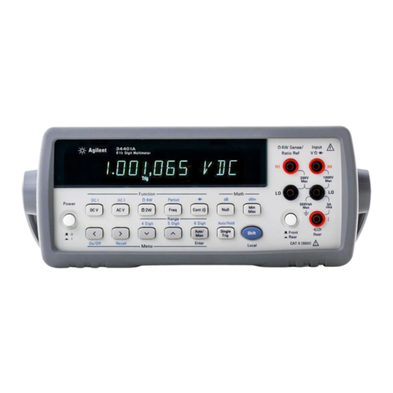
HP 34401A
6.5 Digit Multimeter
A l l t r a d e m a r k s , b r a n d n a m e s , a n d b r a n d s a p p e a r i n g h e r e i n a r e t h e p r o p e r t y o f t h e i r r e s p e c t i v e o w n e r s .
• C r i t i c a l a n d e x p e d i t e d s e r v i c e s
• I n s t o c k / R e a d y - t o - s h i p
Artisan Scientific Corporation dba Artisan Technology Group is not an affiliate, representative, or authorized distributor for any manufacturer listed herein.
In Stock
Used and in Excellent Condition
Buy Today!
https://www.artisantg.com/64736-1
• We b u y y o u r e x c e s s , u n d e r u t i l i z e d , a n d i d l e e q u i p me n t
• F u l l - s e r v i c e , i n d e p e n d e n t r e p a i r c e n t e r
Advertisement

Related Manuals for Keysight Technologies 34401A


Summary of Contents for Keysight Technologies 34401A
- Page 1 HP 34401A 6.5 Digit Multimeter In Stock Used and in Excellent Condition Buy Today! https://www.artisantg.com/64736-1 A l l t r a d e m a r k s , b r a n d n a m e s , a n d b r a n d s a p p e a r i n g h e r e i n a r e t h e p r o p e r t y o f t h e i r r e s p e c t i v e o w n e r s .
- Page 2 Keysight 34401A 6½ Digit Multimeter Service Guide...
- Page 5 Notices Warranty Safety Notices © Keysight Technologies 1991 - 201 4 No part of this manual may be reproduced in any The material contained in this form or by any means (including electronic document is provided “as is,” and is...
- Page 6 The switch is not intended as an active multiplexer. Switching while high voltages or currents are present may cause instrument damage and lead to the risk of electric shock. 34401A Service Guide...
- Page 7 Protection Limits Note: The 200 Vpk limit on the sense terminals is the Protection Limit. Operational The Agilent 34401A Digital Multimeter provides voltages in resistance measurements are Input Terminal Protection protection circuitry to prevent damage to the much lower —...
- Page 8 (up to 300 VAC). However, Fine Tip Probe Attachments - 300V, 3A (2002/96/EC) marking requirement. The affixed the 34401A may not be used with its HI and LO product label (see below) indicates that you Mini Grabber Attachment - 300V, 3A...
- Page 9 Declares, that the product Product Name: Multimeter Model Number: 34401A Product Options: This declaration covers all options of the above product(s). Conforms with the following European Directives: The product herewith complies with the requirements of the Low Voltage Directive 73/23/EEC and the EMC Directive 89/336/EEC (including 93/68/EEC) and carries the CE Marking accordingly.
- Page 10 Note: Unless otherwise indicated, this manual applies to all serial numbers. The Agilent Technologies 34401A is a 6 -digit, high-performance ⁄ digital multimeter. Its combination of bench-top and system features makes this multimeter a versatile solution for your measurement needs now and in the future.
- Page 11 The Front Panel at a Glance Measurement Function keys Front / Rear Input Terminal Switch Math Operation keys Range / Number of Digits Displayed keys Single Trigger / Autotrigger / Reading Hold key Menu Operation keys Shift / Local key...
- Page 12 The Front-Panel Menu at a Glance The menu is organized in a top-down tree structure with three levels. A: MEASurement MENU 1: AC FILTER > 2: CONTINUITY > 3: INPUT R > 4: RATIO FUNC > 5: RESOLUTION B: MATH MENU 1: MIN-MAX >...
- Page 13 Display Annunciators ∗ Turns on during a measurement. Multimeter is addressed to listen or talk over the GPIB interface. Adrs Multimeter is in remote mode (remote interface). Multimeter is using manual ranging (autorange is disabled). Multimeter is waiting for a single trigger or external trigger. Trig Reading Hold is enabled.
- Page 14 The Rear Panel at a Glance Chassis Ground Voltmeter Complete Output Terminal Power-Line Fuse-Holder Assembly External Trigger Input Terminal Power-Line Voltage Setting GPIB (IEEE-488) Interface connector Front and Rear Current Input Fuse RS-232 interface connector Use the front-panel Input / Output Menu to: •...
- Page 15 1-800-452-4844 in the United States, or contact your nearest Agilent Sales Office. If your 34401A fails within one year of purchase, Agilent will repair or replace it free of charge. Call 1-877-444-7278 (“Agilent Express”) in the United States, or contact your nearest Agilent Sales Office.
- Page 16 Contents Chapter 1 Specifications DC Characteristics 12 AC Characteristics 14 Frequency and Period Characteristics 16 General Information 18 Product Dimensions 19 To Calculate Total Measurement Error 20 Interpreting Multimeter Specifications 22 Configuring for Highest Accuracy Measurements 25 Chapter 2 Quick Start To Prepare the Multimeter for Use 29 If the Multimeter Does Not Turn On 30 To Adjust the Carrying Handle 32...
- Page 17 Contents Chapter 4 Calibration Procedures Agilent Calibration Services 61 Calibration Interval 61 Time Required for Calibration 61 Automating Calibration Procedures 62 Recommended Test Equipment 63 Test Considerations 64 Performance Verification Tests 65 Zero Offset Verification 67 Gain Verification 69 Optional AC Performance Verification Tests 72 Calibration Security Code 73 Calibration Count 75 Calibration Message 75...
- Page 18 To Order Replaceable Parts 126 Backdating and Part Changes 126 Replaceable Parts: 34401-66501 (Main Assembly) 127 Replaceable Parts: 34401-66512 (Display Assembly) 133 Replaceable Parts: Agilent 34401A Mainframe 134 Manufacturer’s List 135 Chapter 8 Backdating 137 Chapter 9 Schematics Mechanical Disassembly 9-3 Component Locator Diagram –...
- Page 20 Specifications...
- Page 21 Chapter 1 Specifications DC Characteristics DC Characteristics ± ( % of reading + % of range ) [ 1 ] Accuracy Specifications Temperature 24 Hour [ 2 ] Test Current or 90 Day 1 Year Coefficient /°C Range [ 3 ] ±...
- Page 22 Chapter 1 Specifications DC Characteristics [ 8 ] Operating Characteristics Measuring Characteristics Additional DC Voltage Measurement Method: Continuously integrating, multi-slope III Function Digits Readings/s Noise Error DCV, DCI, and 0.6 (0.5) 0% of range ⁄ A/D converter. Resistance ⁄ 6 (5) 0% of range A/D Linearity: 0.0002% of reading + 0.0001% of range...
- Page 23 Chapter 1 Specifications AC Characteristics AC Characteristics Accuracy Specifications ± ( % of reading + % of range ) [ 1 ] Temperature 24 Hour [ 2 ] 90 Day 1 Year Coefficient/°C Range [ 3 ] ± ± ± Function Frequency 23°C...
- Page 24 Chapter 1 Specifications AC Characteristics [ 9 ] Measuring Characteristics Operating Characteristics [ 8 ] Function Digits Reading/s AC Filter Measurement Noise Rejection AC CMRR 70 dB ACV, ACI ⁄ 7 sec/reading Slow Medium ⁄ Fast ⁄ [ 10 ] True RMS AC Voltage Measurement Method: AC-coupled True RMS –...
- Page 25 Chapter 1 Specifications Frequency and Period Characteristics Frequency and Period Characteristics ( % of reading ) [ 1 ] ± Accuracy Specifications Temperature 90 Day [ 2 ] 24 Hour 1 Year Coefficient/°C ± 23°C 5°C ± ± [ 3 ] Function Range Frequency...
- Page 26 Chapter 1 Specifications Frequency and Period Characteristics Measuring Characteristics Operating Characteristics [ 5 ] Function Digits Reading/s Frequency and Period Frequency, ⁄ Measurement Method: Reciprocal-counting technique. Period AC-coupled input using the ⁄ ⁄ ac voltage measurement function. Voltage Ranges: 100 mV rms full scale to 750 V rms. [ 5 ] Auto or manual ranging.
- Page 27 Chapter 1 Specifications General Information General Information General Specifications Triggering and Memory Power Supply: 100 V / 120 V / 220 V / 240 V 10%. Reading Sensitivity: 0.01%, 0.1%, 1%, or 10% of reading ± HOLD Power Line Frequency: 45 Hz to 66 Hz and 360 Hz to 440 Hz.
- Page 28 Chapter 1 Specifications Product Dimensions Product Dimensions Product Dimensions 103.8 mm 261.1 mm 379.4 mm 88. 5 mm 212. 6 mm 348. 3 mm All dimensions are shown in millimeters.
- Page 29 Chapter 1 Specifications To Calculate Total Measurement Error To Calculate Total Measurement Error Each specification includes correction factors which account for errors present due to operational limitations of the multimeter. This section explains these errors and shows how to apply them to your measurements. Refer to “Interpreting Multimeter Specifications,”...
- Page 30 Chapter 1 Specifications To Calculate Total Measurement Error Understanding the “ % of range ” Error The range error compensates for inaccuracies that result from the function and range you select. The range error contributes a constant error, expressed as a percent of range, independent of the input signal level.
- Page 31 ⁄ ” digit. For example, the Agilent 34401A can measure 9.99999 Vdc on the 10 V range. This represents six full digits of resolution. The multimeter can also overrange on the 10 V range and measure up to a maximum of 12.00000 Vdc.
- Page 32 This means that you can achieve greater actual measurement precision for a specific accuracy specification number. The Agilent 34401A is designed and tested to meet performance better 4 sigma of the published accuracy specifications. than mean...
- Page 33 Chapter 1 Specifications Interpreting Multimeter Specifications Transfer Accuracy Transfer accuracy refers to the error introduced by the multimeter due to noise and short-term drift. This error becomes apparent when comparing two nearly-equal signals for the purpose of “transferring” the known accuracy of one device to the other. 24-Hour Accuracy The 24-hour accuracy specification indicates the multimeter’s relative accuracy over its full measurement range for short time intervals and...
- Page 34 Chapter 1 Specifications Configuring for Highest Accuracy Measurements Configuring for Highest Accuracy Measurements The measurement configurations shown below assume that the multimeter is in its power-on or reset state. It is also assumed that manual ranging is enabled to ensure proper full scale range selection. DC Voltage, DC Current, and Resistance Measurements: Set the resolution to 6 digits (you can use the 6 digits slow mode for •...
- Page 36 Quick Start...
- Page 37 Quick Start One of the first things you will want to do with your multimeter is to become acquainted with its front panel. We have written the exercises in this chapter to prepare the multimeter for use and help you get familiar with some of its front-panel operations.
- Page 38 Chapter 2 Quick Start To Prepare the Multimeter for Use To Prepare the Multimeter for Use The following steps help you verify that the multimeter is ready for use. 1 Check the list of supplied items. Verify that you have received the following items with your multimeter. If anything is missing, contact your nearest Agilent Sales Office.
- Page 39 Chapter 2 Quick Start If the Multimeter Does Not Turn On If the Multimeter Does Not Turn On Use the following steps to help solve problems you might encounter when turning on the multimeter. If you need more help, see chapter 6 for instructions on returning the multimeter to Agilent for service.
- Page 40 Chapter 2 Quick Start If the Multimeter Does Not Turn On Remove the power cord. Remove the Remove the line-voltage selector from fuse-holder assembly from the rear panel. the assembly. See rear panel for proper fuse rating. Agilent Part Number: 2110-0817 (250 mAT) Rotate the line-voltage selector until the Replace the fuse-holder assembly in correct voltage appears in the window.
- Page 41 Chapter 2 Quick Start To Adjust the Carrying Handle To Adjust the Carrying Handle To adjust the position, grasp the handle by the sides and pull outward. Then, rotate the handle to the desired position. Bench-top viewing positions Carrying position...
- Page 42 Chapter 2 Quick Start To Measure Voltage To Measure Voltage Ranges: 100 mV, 1 V, 10 V, 100 V, 1000 V (750 Vac) Maximum resolution: 100 nV (on 100 mV range) AC technique: true , ac-coupled To Measure Resistance Ranges: 100 Ω, 1 kΩ, 10 kΩ, 100 kΩ, 1 MΩ, 10 MΩ, 100 MΩ Maximum resolution: 100 µΩ...
- Page 43 Chapter 2 Quick Start To Measure Current To Measure Current Ranges: 10 mA (dc only), 100 mA (dc only), 1 A , 3 A Maximum resolution: 10 nA (on 10 mA range) AC technique: true , ac-coupled To Measure Frequency (or Period) Measurement band: 3 Hz to 300 kHz (0.33 sec to 3.3 µsec) Input signal range: 100 mVac to 750 Vac Technique: reciprocal counting...
- Page 44 Chapter 2 Quick Start To Test Continuity To Test Continuity Test current source: 1 mA Maximum resolution: 0.1 Ω (range is fixed at 1 kohm) Beeper threshold: 1 Ω to 1000 Ω (beeps below adjustable threshold) To Check Diodes Test current source: 1 mA Maximum resolution: 100 µV (range is fixed at 1 Vdc) Beeper threshold: 0.3 volts ≤...
- Page 45 Chapter 2 Quick Start To Select a Range To Select a Range You can let the multimeter automatically select the range using autoranging or you can select a fixed range using manual ranging. Selects a lower range and disables autoranging. Selects a higher range and disables autoranging.
- Page 46 Chapter 2 Quick Start To Set the Resolution To Set the Resolution You can set the display resolution to 4 , or 6 digits either to ⁄ ⁄ ⁄ optimize measurement speed or noise rejection. In this book, the most significant digit (leftmost on the display) is referred to as the “...
- Page 47 Chapter 2 Quick Start To Make Null (Relative) Measurements To Make Null (Relative) Measurements Each null measurement, also called relative, is the difference between a stored null value and the input signal. Result = reading – null value To read / edit the null value, use the MATH menu. Enables null operation;...
- Page 48 Chapter 2 Quick Start To Store Minimum and Maximum Readings To Store Minimum and Maximum Readings You can store the minimum and maximum readings during a series of measurements. The following discussion shows how to read the minimum, maximum, average, and reading count. To read the minimum, maximum, average, and count, use the MATH menu.
- Page 49 Chapter 2 Quick Start To Make dB Measurements To Make dB Measurements Each dB measurement is the difference between the input signal and a stored relative value, with both values converted to dBm. dB = reading in dBm – relative value in dBm To read / edit the dB relative value, use the MATH menu.
- Page 50 Chapter 2 Quick Start To Make dBm Measurements To Make dBm Measurements The dBm operation calculates the power delivered to a resistance referenced to 1 milliwatt. dBm = 10 × Log ( reading reference resistance 1 mW ) To read / edit the dBm reference resistance, use the MATH menu.
- Page 51 Chapter 2 Quick Start To Trigger the Multimeter To Trigger the Multimeter You can trigger the multimeter from the front panel using single trigger or auto trigger. ∗ Enables single trigger (sample) annunciator is on and triggers the multimeter. during each measurement. Toggles between auto trigger Trig annunciator is on when the and reading hold.
- Page 52 Chapter 2 Quick Start To Make dcv:dcv Ratio Measurements To Make dcv:dcv Ratio Measurements To calculate a ratio, the multimeter measures a dc reference voltage applied to the Sense terminals and the voltage applied to the Input terminals. voltage signal Ratio dc referencevoltage To enable ratio measurements, use the MEAS menu.
- Page 53 Chapter 2 Quick Start Front-Panel Display Formats Front-Panel Display Formats Negative sign or blank (positive) – ⁄ “ ” digit (0 or 1) Numeric digits H.DDD,DDD EFFF Exponent ( m, k, M ) Measurement units ( VDC, OHM, HZ, dB ) Front-panel display format.
- Page 54 Instructions and mounting hardware are included with each rack-mounting kit. Any Agilent System II instrument of the same size can be rack-mounted beside the 34401A. Remove the carrying handle, and the front and rear rubber bumpers, before rack-mounting the multimeter.
- Page 55 Chapter 2 Quick Start To Rack Mount the Multimeter To rack mount a single instrument, order adapter kit 5063-9240. To rack mount two instruments side-by-side, order lock-link kit 5061-9694 and flange kit 5063-9212. To install one or two instruments in a sliding support shelf, order shelf 5063-9255, and slide kit 1494-0015 (for a single instrument, also order filler panel 5002-3999).
- Page 56 Menu Tutorial...
- Page 57 Menu Tutorial By now you should be familiar with the FUNCTION RANGE / DIGITS groups of front-panel keys. You should also understand how to make front-panel connections for the various types of measurements. If you are not familiar with this information, we recommend that you read chapter 2, “Quick Start,”...
- Page 58 Chapter 3 Menu Tutorial Front-Panel Menu Reference Front-Panel Menu Reference A: MEASurement MENU 1: AC FILTER > 2: CONTINUITY > 3: INPUT R > 4: RATIO FUNC > 5: RESOLUTION Selects the slow, medium, or fast ac filter. 1: AC FILTER Sets the continuity beeper threshold (1 Ω...
- Page 59 Chapter 3 Menu Tutorial Front-Panel Menu Reference D: SYStem MENU 1: RDGS STORE > 2: SAVED RDGS > 3: ERROR > 4: TEST > 5: DISPLAY > 6: BEEP > 7: COMMA > 8: REVISION Enables or disables reading memory. 1: RDGS STORE Recalls readings stored in memory (up to 512 readings).
- Page 60 Chapter 3 Menu Tutorial A Front-Panel Menu Tutorial A Front-Panel Menu Tutorial This section is a step-by-step tutorial which shows how to use the front-panel menu. We recommend that you spend a few minutes with this tutorial to get comfortable with the structure and operation of the menu. The menu is organized in a top-down tree structure with three levels (menus, commands, and parameters).
- Page 61 Chapter 3 Menu Tutorial A Front-Panel Menu Tutorial MESSAGES DISPLAYED DURING MENU USE ∧ You pressed while on the “menus” level; this is the top level of TOP OF MENU the menu and you cannot go any higher. Shift < To turn off the menu, press (Menu On/Off).
- Page 62 Chapter 3 Menu Tutorial A Front-Panel Menu Tutorial The following steps show you how to turn on the menu, move up or down Menu Example 1 between levels, move across the choices on each level, and turn off the menu. In this example, you will unsecure the multimeter for calibration. On/Off Shift <...
- Page 63 Chapter 3 Menu Tutorial A Front-Panel Menu Tutorial ∨ 4 Move down to the “parameters” level. The multimeter will wait for the security code to be entered. ^000000 CODE 5 Unsecure the multimeter by entering the security code. The security code is set to “ ”...
- Page 64 Chapter 3 Menu Tutorial A Front-Panel Menu Tutorial Some commands in the menu require that you enter a numeric parameter Menu Example 2 value. The following steps show you how to enter a number in the menu. In this example, you will set the calibration value to 0.0 volts. For this example you must apply a short between HI-LO Sense and HI-LO Input .
- Page 65 Chapter 3 Menu Tutorial A Front-Panel Menu Tutorial ∨ 3 Move down to the “commands” level within the CAL MENU Either is the first command on this level. SECURED UNSECURED To perform a calibration, must be displayed. If UNSECURED SECURED is displayed, see example 1 in this chapter to unsecure for calibration.
- Page 66 Chapter 3 Menu Tutorial A Front-Panel Menu Tutorial ∨ 7 Decrement the first digit until “0” is displayed. You decrement or increment each digit independently. Neighboring digits are not affected. 000.000,0 mVDC < < 8 Move the flashing cursor over to the “units” location. Notice that the units are flashing on the right side of the display.
- Page 68 Calibration Procedures...
- Page 69 Calibration Procedures Agilent Calibration Services 61 • Calibration Interval 61 • Time Required for Calibration 61 • Automating Calibration Procedures 62 • Recommended Test Equipment 63 • Test Considerations 64 • Performance Verification Tests 65 • Zero Offset Verification 67 •...
- Page 70 Whatever calibration interval you select, Agilent recommends that complete re-adjustment should always be performed at the calibration interval. This will increase your confidence that the Agilent 34401A will remain within specification for the next calibration interval. This criteria for re-adjustment provides the best measure of the multimeter’s long-term stability.
- Page 71 If you are using the Agilent 34401A in the Fluke 8840A/8842A emulation mode, you cannot use the Fluke calibration commands. You must use the SCPI calibration commands described in chapter 4 of the Agilent 34401A User’s Guide.
- Page 72 A suggested alternate method would be to use the Agilent 3458A 8 ⁄ digit Digital Multimeter to measure less accurate yet stable sources. The output value measured from the source can be entered into the 34401A Multimeter as the target calibration value.
- Page 73 Chapter 4 Calibration Procedures Test Considerations Test Considerations To ensure proper instrument operation, verify that you have selected the correct power-line voltage prior to attempting any test procedure in this chapter. See chapter 2, “Quick Start,” for more information. Ensure that all measurement terminal connections (both front panel and rear panel) are removed while the multimeter’s internal self-test is being performed.
- Page 74 . You can also perform a self-test from TEST SYS MENU the remote interface. For further information, see chapter 3 in the Agilent 34401A User’s Guide. If the self-test is successful, “ ” is displayed on the front panel. PASS •...
- Page 75 Chapter 4 Calibration Procedures Performance Verification Tests Quick Performance Check The quick performance check is a combination of internal self-test and an abbreviated performance test (specified by the letter Q in the performance verification tests). This test provides a simple method to achieve high confidence in the multimeter’s ability to functionally operate and meet specifications.
- Page 76 Chapter 4 Calibration Procedures Zero Offset Verification Zero Offset Verification This procedure is used to check the zero offset performance of the multimeter. Verification checks are only performed for those functions and ranges with unique offset calibration constants. A low-thermal four-terminal short is applied to the input of the multimeter.
- Page 77 Caution Zero offset calibration using a multifunction calibrator is recommended. The calibrator and cabling offset can be large and unstable causing poor offset calibration of the Agilent 34401A or any multimeter. Note These offset tests should be verified for both the front and the rear...
- Page 78 Select each function and range in the order shown below. Compare measurement results to the appropriate test limits shown in the table. (Be certain to allow for appropriate source settling.) Error From Nominal Input Quick 34401A (Front) Function Check Range 24 hour...
- Page 79 2 Select each function and range in the order shown below. Compare measurement results to the appropriate test limits shown in the table. (Be certain to allow for appropriate source settling.) Error From Nominal Input Input 34401A Quick (Front) Frequency Range 24 hour...
- Page 80 2 Select each function and range in the order shown below. Compare measurement results to the appropriate test limits shown in the table. (Be certain to allow for appropriate source settling.) Error From Nominal Input Input 34401A (Front) Frequency Range 24 hour 90 day...
- Page 81 2 Select each function and range in the order shown below. Compare measurement results to the appropriate test limits shown in the table. (Be certain to allow for appropriate source settling.) Error From Nominal Input Input 34401A (Front) Frequency Range 24 hour 90 day...
- Page 82 Chapter 4 Calibration Procedures Calibration Security Code Calibration Security Code This feature allows you to enter a security code (electronic key) to prevent accidental or unauthorized calibrations of the multimeter. When you first receive your multimeter, it is secured. Before you can adjust calibration constants you must unsecure the meter by entering the correct security code.
- Page 83 Chapter 4 Calibration Procedures Calibration Security Code To Unsecure the Multimeter Without the Security Code To unsecure the meter without the correct security code, follow the steps below. Chapter 9, “Schematics,” contains the schematics associated with this procedure. See example 1 in chapter 3, “Menu Tutorial,” starting on page 53, for an example of entering the security code.
- Page 84 Chapter 4 Calibration Procedures Calibration Count Calibration Count The calibration count feature provides an independent “serialization” of your calibrations. You can determine the number of times that your multimeter has been calibrated. By monitoring the calibration count, you can determine whether an unauthorized calibration has been performed.
- Page 85 Chapter 4 Calibration Procedures Calibration Procedures Calibration Procedures Before beginning any adjustment procedures, the multimeter must be in the “ ” state. To unsecure the multimeter, see “Calibration UNSECURED Security Code” on page 73. Each adjustment should be followed by a performance verification check for added confidence.
- Page 86 Chapter 4 Calibration Procedures Zero Adjustment Zero Adjustment Each time you perform a zero adjustment, the multimeter stores a new set of offset correction constants for every measurement function and range. Separate offset correction constants are stored for the front and rear input terminals.
- Page 87 Chapter 4 Calibration Procedures Zero Adjustment Zero Adjustment (continued) 2 Select the shorted terminal set (front or rear terminal) with the front/rear switch. Separate calibration constants are stored for the front and rear input terminals. 3 Turn on the menu ( ) and then use Shift <...
- Page 88 Chapter 4 Calibration Procedures Gain Adjustment Gain Adjustment The multimeter stores a single new gain correction constant each time this procedure is followed. The gain constant is computed from the calibration value entered for the calibration command and from measurements made automatically during the adjustment procedure. Most measuring functions and ranges have gain adjustment procedures.
- Page 89 Chapter 4 Calibration Procedures Gain Adjustment Valid Gain Adjustment Input Values Gain adjustment can be accomplished using the following input values. Function Range Valid Calibration Input Values DC V 100 mV to 100 V 0.9 to 1.1 x Full Scale 1000 V 900 V to 1050 V Ω...
- Page 90 Chapter 4 Calibration Procedures Gain Adjustment 3 Turn on the menu ( ) and then use to select Shift < < > F: CAL MENU 4 Use to move down to the “commands” level and select ∨ 2. CALIBRATE 5 Use to move down to the “parameters”...
- Page 91 Optional Gain Calibration Procedures The optional calibrations in this section are used to enhance the performance of your Agilent 34401A Multimeter. These calibrations are normally performed at the factory. These adjustments should be performed following the repair of your multimeter. You are not required to perform these adjustments at any other interval.
- Page 92 Chapter 4 Calibration Procedures Optional Gain Calibration Procedures 500 Vdc Adjustment Procedure The 500 Vdc calibration electronically corrects the multimeter’s 100:1 divider network ( ) linearity characteristic for minimum error. U101 This adjustment should be performed only after replacement of the divider network or the calibration U101...
- Page 93 Chapter 4 Calibration Procedures Optional Gain Calibration Procedures 1/100th Scale AC Adjustment Procedure This calibration procedure is used to enhance the ac volts and ac current measurement accuracy for <1/100th scale inputs. The single calibration generates a correction constant used for all ranges of the ac volts and ac current measuring functions.
- Page 94 Chapter 4 Calibration Procedures Understanding the AC Signal Filter Understanding the AC Signal Filter The multimeter uses three different ac filters which enable you to either optimize low frequency accuracy or achieve faster ac settling times. The multimeter selects the slow, medium, or fast filter based on the input frequency that you specify.
- Page 95 Chapter 4 Calibration Procedures Understanding Resolution Understanding Resolution Resolution is expressed in terms of number of digits the multimeter can measure or display. You can set the resolution to 4, 5, or 6 full digits, ⁄ plus a “ ” digit which can only be a “0” or “1”. To increase measurement accuracy and improve noise rejection, select 6 digits.
- Page 96 Chapter 4 Calibration Procedures Understanding Resolution 5 digits 10.216,5 ⁄ “ ” digit ⁄ This is the 10 Vdc range, 5 digits are displayed. ⁄ “ ” digit 045.23 mVDC ⁄ This is the 100 mVdc range, 4 digits are displayed. 113.325,6 OHM ⁄...
- Page 97 Chapter 4 Calibration Procedures Understanding Resolution Front-Panel Operation: Select either the slow or fast mode for each • Resolution resolution setting. The default mode is 5 digits slow. (continued) 5: RESOLUTION (MEAS MENU) See also “To Set the Resolution,” on page 37. Remote Interface Operation: You can set the resolution using the •...
- Page 98 They are intended to include errors which are likely to be encountered during the procedures described in this chapter. For a more complete list of error messages and descriptions, see chapter 5 in the Agilent 34401A User’s Guide. System Error Messages Self-Test Error Messages...
- Page 99 Chapter 4 Calibration Procedures Error Messages Calibration Error Messages Error Error Message Cannot calibrate rundown gain Rundown gain out of range Cal security disabled by jumper Cal secured Invalid secure code Secure code too long Cal aborted Cal value out of range Cal signal measurement out of range Cal signal frequency out of range No cal for this function or range...
- Page 100 Theory of Operation...
- Page 101 Theory of Operation This chapter is organized to provide descriptions of the circuitry contained on each schematic shown in chapter 9. A block diagram overview is provided in this chapter followed by more detailed descriptions of the circuitry contained in the schematics chapter. Block Diagram 93 •...
- Page 102 Chapter 5 Theory of Operation Block Diagram Block Diagram Referring to the block diagram on page 9-7, you will notice that the multimeter’s circuitry is divided into two major blocks: the floating circuitry and the earth (ground) referenced circuitry. All measurement, control, and display functions are contained in the floating section.
- Page 103 Chapter 5 Theory of Operation Front/Rear Selection Front/Rear Selection Referring to the front/rear schematic on page 9-8, the purpose of this circuitry is to select either the front terminals or the rear terminals (via switch ). The output of is connected to the Function Switching schematic (see page 9-9).
- Page 104 Chapter 5 Theory of Operation Function Switching Function Switching The purpose of the Function Switching section (schematic shown on page 9-9) is to connect the Input HI terminal to the various measuring functions. This is accomplished through , and K101 K102 K103 K104...
- Page 105 Chapter 5 Theory of Operation DC Amplifier DC Amplifier The DC Amplifier circuit (schematic shown on page 9-10) is used by every measuring function except frequency and period. Analog switch selects various input signals for measurement by the U101B Switch has three sources which can be dynamically selected: U101B measure customer input (...
- Page 106 Chapter 5 Theory of Operation DC Amplifier In the DC current function, a current is applied between the Input I and terminals. Ranging is accomplished by relay and amplifier gain K102 switching in . Since a known resistor (the shunt resister) is connected U101 between these terminals, a voltage proportional to the unknown current is generated.
- Page 107 Chapter 5 Theory of Operation Ohms Current Source Ohms Current Source The ohms current source (schematic shown on page 9-10) flows from the terminal to the Input LO terminal for both the 2-wire and 4-wire Input HI ohms functions. Each current value is generated by forcing a stable, precise voltage across a stable resistance.
- Page 108 Chapter 5 Theory of Operation AC Circuit AC Circuit Referring to the schematic shown on page 9-11, the multimeter uses a true ac-to-dc converter to measure ac voltages and currents. The ac-to-dc converter changes the input ac voltage to a dc voltage. All voltage ranging is performed in the ac circuit so that the input to the multimeter’s dc circuitry ( ) is nominally 2 Vdc for a full scale...
- Page 109 Chapter 5 Theory of Operation AC Circuit The programmable capacitance is implemented by varying the signal level across a compensating capacitor. In the x0.2 configuration, low frequency gain is set by , and . The variable gain element R301 R302 R304 essentially varies the value of from 0 to 1 times its value...
- Page 110 , and residue U501 ADC U500 method used by the 34401A is called multislope III. It is based on patented Agilent technology. Multislope III is a charge balancing continuously integrating analog-to-digital converter. The charge balancing algorithm is always running, even when the multimeter is not triggered.
- Page 111 Chapter 5 Theory of Operation A-to-D Converter Each analog-to-digital conversion begins when the multimeter is triggered. The starts by clearing the integrator slope count in U501 At the end of the integration period, the slope count is latched. The slope count provides the most significant bits of the input voltage conversion.
- Page 112 Chapter 5 Theory of Operation Floating Logic Floating Logic Referring to the schematic shown on page 9-13, the floating common logic controls operation of the entire instrument. All measurement control and bus command interpretation is performed in the main . The front panel and earth referenced processors operate as slaves U500 .
- Page 113 Chapter 5 Theory of Operation Floating Logic The counter register is used to capture either slope count at the input or frequency count at the input. The input COMP FREQIN COMP functions as both a clocked comparator and the slope counter input for .
- Page 114 Chapter 5 Theory of Operation Earth-Referenced Logic The main processor has an on chip 10-bit successive approximation with two selectable inputs: . The input is FLASH FREQRNG FLASH used to sample the residual charge on the main integrating output . The input is used to make voltage ranging decisions U402 FREQRNG...
- Page 115 Chapter 5 Theory of Operation Power Supplies Power Supplies Referring to the schematic shown on page 9-15, the multimeter uses two types of power supplies: floating supplies and earth referenced supplies. The floating supply outputs are 18 Vdc, +5 Vdc, and a 5 Vrms center ±...
- Page 116 Chapter 5 Theory of Operation Front Panel Front Panel The front panel circuits (schematic shown on page 9-16) consist of vacuum fluorescent display control, display high voltage drivers, and keyboard scanning. Communication between the front panel and floating logic circuits is accomplished through a 4-wire bidirectional serial interface.
- Page 118 Service...
- Page 119 Service This chapter discusses the procedures involved for returning a failed multimeter to Agilent for service or repair. Subjects covered include the following: Operating Checklist 111 • Types of Service Available 112 • Repackaging for Shipment 113 • Electrostatic Discharge (ESD) Precautions 114 •...
- Page 120 Chapter 6 Service Operating Checklist Operating Checklist Before returning your multimeter to Agilent for service or repair, check the following items: Is the multimeter inoperative? Verify that the ac power cord is connected to the multimeter. Verify that the front-panel Power switch is depressed. Verify that the power-line fuse is good.
- Page 121 Contact your nearest Agilent Service Center. They will arrange to have your multimeter repaired or replaced. Agilent Express Service (U.S. only) You can receive a replacement 34401A via overnight shipment for short downtime. 1 Call 1-877-444-7278 and ask for “Agilent Express.”...
- Page 122 Repackaging for Shipment For the Agilent Express Service described on the previous page, return your failed 34401A to the designated Agilent Service Center using the shipping carton of the exchange unit. A shipping label will be supplied. Agilent will notify you when your failed unit has been received.
- Page 123 Chapter 6 Service Electrostatic Discharge (ESD) Precautions Electrostatic Discharge (ESD) Precautions Almost all electrical components can be damaged by electrostatic discharge ( ) during handling. Component damage can occur at electrostatic discharge voltages as low as 50 volts. The following guidelines will help prevent damage when servicing the multimeter or any electronic device.
- Page 124 Chapter 6 Service To Replace the Current Input Fuses To Replace the Current Input Fuses The front and rear current input terminals are protected by two series fuses. The first fuse is a 3 A, 250 Vac, fast-blow fuse and is located on the rear panel.
- Page 125 Chapter 6 Service To Connect the Pass/Fail Output Signals Pass/Fail Output (continued) Installation Procedure The assembly drawings and schematics are located in chapter 9, “Schematics.” 1 Unscrew the two rear bezel captive screws (see the mechanical disassembly drawing on page 9-3). 2 Remove one screw from bottom cover (see the mechanical disassembly drawing on page 9-3).
- Page 126 Chapter 6 Service Troubleshooting Hints Troubleshooting Hints This section provides a brief check list of common failures. Before troubleshooting or repairing the multimeter, make sure the failure is in the instrument rather than any external connections. Also make sure that the instrument is accurately calibrated. The multimeter’s circuits allow troubleshooting and repair with basic equipment such as a ⁄...
- Page 127 Chapter 6 Service Troubleshooting Hints Troubleshooting Current input is inoperative Hints (continued) Verify that the rear panel 3 A, 250 V current fuse is functional. Verify that the internal 7 A, 250 V high-interrupt fuse is functional. Power supply problems Check that the input to the supply voltage regulator is at least 1 V greater than its output.
- Page 128 Chapter 6 Service Troubleshooting Hints Readings are inaccurate Inaccurate readings are normally caused by either invalid calibration or by non-linear measuring circuits. If recalibration does not correct the inaccuracies, the amplifier or solid state switches may be causing measurement non-linearities. Non-linear operation of the ohms current source due to failure of may cause reading inaccuracies in Q202...
- Page 129 Failing a self-test procedure indicates that parts of the multimeter are not functioning properly and need to be serviced. Passing self-test gives a better than 90% confidence that the Agilent 34401A hardware is operational. However, passing self-test does not guarantee that the multimeter will produce accurate results.
- Page 130 Chapter 6 Service Self-Test Procedures Self-test procedures are numbered in the order in which they are executed. The order is designed to build confidence from a small kernel towards progressively more complex internal configurations. Many individual self-test procedures may be executed from the front panel by selecting the desired test number from the parameter list of command (in the TEST...
- Page 131 Chapter 6 Service Self-Test Procedures Rundown too noisy This test checks the gain repeatability between the integrating and the onchip . The gain test (606), is U500 performed eight times. Gain noise must be less than 64 lsb’s of the ±...
- Page 132 Chapter 6 Service Self-Test Procedures Ohms 10 uA source failed This test configures to the 10 V dc range with the internal 10 M 100:1 divider connected across the input. U102A The 10 A ohms current source is connected. The compliance limit of the µ...
- Page 133 Chapter 6 Service Self-Test Procedures Frequency counter failed This test configures for the 100 mV ac range. This test immediately follows test 621. With holding a C301 charge from test 621 the ac input is now switched to ground with K103 This produces a positive pulse on the input to the frequency comparator .
- Page 134 Replaceable Parts...
- Page 135 Replaceable Parts This section contains information for ordering replacement parts for your Agilent 34401A Multimeter. The parts lists are divided into the following groups. 34401-66501 Main PC Assembly (A1) page 127 • 34401-66512 Front-Panel Display PC Assembly (A2) page 133 •...
- Page 136 Chapter 7 Replaceable Parts 34401-66501 – Main PC Assembly (A1) 34401-66501 – Main PC Assembly (A1) Reference Agilent Part Mfr. Designation Number Part Description Code Mfr. Part Number Capacitor-Fxd 470 pF ±2% 630 V C100 0160-6839 28480 0160-6839 Capacitor-Fxd 220 pF ±2% 630 V C101-C103 0160-6842 28480...
- Page 137 Chapter 7 Replaceable Parts 34401-66501 – Main PC Assembly (A1) Reference Agilent Part Mfr. Designation Number Part Description Code Mfr. Part Number Capacitor-Fxd 0.1 uF ±10% 50 V C506 0160-6497 04222 12065C104KAT A Capacitor-Fxd 47 uF ±20% 10 V C512 0180-4228 28480 0180-4228...
- Page 138 Chapter 7 Replaceable Parts 34401-66501 – Main PC Assembly (A1) Reference Agilent Part Mfr. Designation Number Part Description Code Mfr. Part Number J704 1252-2266 Connector-Rect D-Submin 9-Ckt 9-Contact 00779 748959-1 JM501 0699-1503 Resistor-Fxd 0 CWM 91637 CRCW1206000J JM551-JM553 0699-1503 Resistor-Fxd 0 CWM 91637 CRCW1206000J JM751...
- Page 139 Chapter 7 Replaceable Parts 34401-66501 – Main PC Assembly (A1) Reference Agilent Part Mfr. Designation Number Part Description Code Mfr. Part Number Resistor 14.7K ±1% .125W R130 0699-1394 28480 0699-1394 Resistor 21.5K ±1% .125W R131 0699-1398 28480 0699-1398 Resistor 10K ±1% .125W R150 0699-1391 28480...
- Page 140 Chapter 7 Replaceable Parts 34401-66501 – Main PC Assembly (A1) Reference Agilent Part Mfr. Designation Number Part Description Code Mfr. Part Number R430 0699-1503 Resistor Zero Ohm 28480 0699-1503 Resistor 42.2K ±1% .125W R440 0699-1406 28480 0699-1406 Resistor 14.7K ±1% .125W R441 0699-1394 28480...
- Page 141 Chapter 7 Replaceable Parts 34401-66501 – Main PC Assembly (A1) Reference Agilent Part Mfr. Designation Number Part Description Code Mfr. Part Number U201 1826-2420 IC-Op Amp LP Dual 8-Pin 24355 AD706JR U301 1826-2436 IC-Op Amp Wideband 8-pin 27014 LF356M U302 1826-2339 IC-Converter D/A 8-Bit CMOS 24355...
- Page 142 Chapter 7 Replaceable Parts 34401-66512 – Display Assembly (A2) 34401-66512 – Display Assembly (A2) Reference Agilent Part Mfr. Designation Number Part Description Code Mfr. Part Number C602 0160-5945 Capacitor-Fxd 0.01uF 50 V 04222 08055C103KAT A C603-C605 0160-6497 Capacitor-Fxd 0.1uF 25 V 04222 12065C104KAT A C606-C607...
- Page 143 28480 9100-4972 Exchange Unit 34401-69211 Rebuilt 34401A Unit for Exchange 28480 34401-69211 For serial numbers prior to 3146A31949, use a 3A, 250Vac fuse (p/n 2110-0780) for 220 or 240 Vac operation; for all other serial numbers, use a 250 mAT fuse (p/n 2110-0817) for all line voltages.
- Page 144 Chapter 7 Replaceable Parts Manufacturer’s List Manufacturer’s List Mfr. Code Manufacturer’s Name Manufacturer’s Address Zip Code 00779 AMP Inc Harrisburg, PA U.S.A. 17111 01121 Allen-Bradley Co Inc El Paso, TX U.S.A. 79935 01295 Texas Instruments Inc Dallas, TX U.S.A. 75265 01686 RCL Electronics Inc Northbrook, IL U.S.A.
- Page 146 Backdating...
- Page 147 Backdating The table below lists all 34401A changes with prior serial numbers. This information is provided for backdating purposes only. Approx. Effected Delete or Reference Agilent Part Effected Serial Numbers Modify Part Designation Number Part Description Schematic Modify A1U700 34401-88842...
- Page 148 Chapter 8 Backdating Agilent 34401A Multimeter 34401-66522 Display Assembly Replaceable Parts List Reference Agilent Part Mfr. Designation Number Part Description Code Mfr. Part Number Capacitor-Fxd 0.1 uF ±10% 50 V C600-C601 0160-6497 04222 12065C104KAT A Capacitor-Fxd 1 uF ±20% 35 V...
- Page 149 Chapter 8 Backdating Agilent 34401A Multimeter 34401-66522 Display Assembly Component Locator...
- Page 150 34401-66502 Schematic...
- Page 151 Schematics...
- Page 152 Mechanical Disassembly 9-3 • Component Locator Diagram – Main Board (34401-66501) 9-5 • Component Locator Diagram – Front Panel (34401-66512) 9-6 • Agilent 34401A Block Diagram 9-7 • Front/Rear Selection Schematic 9-8 • Function Switching Schematic 9-9 • DC Amplifier and Ohms Schematic 9-10 •...
- Page 153 Mechanical Disassembly...
- Page 154 Mechanical Disassembly...
- Page 155 Component Locator Diagram Main PC Board (34401-66501)
- Page 156 Component Locator Diagram Front-Panel PC Board (34401-66512)
- Page 157 Agilent 34401A Block Diagram...
- Page 158 34401-66501 (sheet 1 of 8) Front/Rear Selection Schematic...
- Page 159 34401-66501 (sheet 2 of 8) Function Switching Schematic...
- Page 160 34401-66501 (sheet 3 of 8) DC Amplifier and Ohms Schematic 9-10...
- Page 161 34401-66501 (sheet 4 of 8) AC Circuit Schematic 9-11...
- Page 162 34401-66501 (sheet 5 of 8) A/D Converter Schematic 9-12...
- Page 163 34401-66501 (sheet 6 of 8) Floating Logic Schematic 9-13...
- Page 164 34401-66501 (sheet 7 of 8) Earth-Referenced Logic Schematic 9-14...
- Page 165 34401-66501 (sheet 8 of 8) Power Supplies Schematic 9-15...
- Page 166 34401-66512 (sheet 1 of 1) Display and Keyboard Schematic 9-16...
- Page 168 This information is subject to change without notice. © Keysight Technologies 1991 - 2014 Edition 9, August 2014 *34401-90013* 34401-90013 www.keysight.com...
Need help?
Do you have a question about the 34401A and is the answer not in the manual?
Questions and answers