Table of Contents
Advertisement
Quick Links
Advertisement
Table of Contents
Troubleshooting

Related Manuals for Keysight Technologies U1253B


Summary of Contents for Keysight Technologies U1253B
- Page 1 Keysight U1253B True RMS OLED Multimeter User’s and Service Guide...
- Page 2 FAR 27.401 or DFAR 227.7103-5 (c), as applicable in any Do not proceed beyond a WARNING technical data. notice until the indicated conditions are fully understood and met. Keysight U1253B User’s and Service Guide...
-
Page 3: Safety Symbols
In position of a bi-stable push control CAT III Category III 1000 V overvoltage Equipotentiality 1000 V protection Equipment protected tshroughout by Category IV 600 V overvoltage CAT IV double insulation or reinforced protection 600 V insulation Keysight U1253B User’s and Service Guide... -
Page 4: General Safety Information
– Never measure voltage when current measurement is selected. – Use only the recommended rechargeable battery. Ensure proper insertion of battery in the multimeter, and follow the correct polarity. – Disconnect test leads from all the terminals during battery charging. Keysight U1253B User’s and Service Guide... - Page 5 – Inspect the test probes for damaged insulation or exposed metal, and check for continuity. Do not use the test probe if it is damaged. – Do not use any other AC charger adapter apart from the one certified by Keysight with this product. Keysight U1253B User’s and Service Guide...
- Page 6 – Do not substitute parts or modify equipment to avoid the danger of introducing additional hazards. Return the product to the nearest Keysight Technologies Sales and Service office for service and repair to ensure the safety features are maintained. – Do not operate damaged equipment as the safety protection features built into this product may have been impaired, either through physical damage, excessive moisture, or any other reason.
-
Page 7: Environmental Conditions
–40 °C to 70 °C (with battery removed) Altitude Up to 2000 m Pollution degree Pollution Degree 2 The U1253B True RMS OLED Multimeter complies with the following safety and NOTE EMC requirements. – IEC 61010-1:2001/EN61010-1:2001 (2nd Edition) – Canada: CAN/CSA-C22.2 No. 61010-1-04 –... -
Page 8: Regulatory Markings
Cet appareil ISM est conforme a la this electrical/electronic product in norme NMB-001 du Canada. domestic household waste. The CSA mark is a registered trademark of the Canadian Standards Association. Keysight U1253B User’s and Service Guide... -
Page 9: Waste Electrical And Electronic Equipment (Weee) Directive 2002/96/ Ec
To contact Keysight for sales and technical support, refer to the support links on the following Keysight websites: – www.keysight.com/find/xxxxx (product-specific information and support, software and documentation updates) – www.keysight.com/find/assist (worldwide contact information for repair and service) Keysight U1253B User’s and Service Guide... -
Page 10: In This Guide
This chapter will show you how to change the default factory settings of the U1253B true RMS OLED multimeter and other available setting options. Maintenance This chapter will help you to troubleshoot if the U1253B true RMS OLED multimeter malfunctions. Performance Tests and Calibration This chapter contains the performance test and adjustment procedures. -
Page 11: Table Of Contents
..........10 Getting Started Introducing the Keysight U1253B True RMS OLED Multimeter ..22 Check the shipment . - Page 12 ........110 Keysight U1253B User’s and Service Guide...
- Page 13 Fuse checking procedure ....... .157 Keysight U1253B User’s and Service Guide...
- Page 14 ........203 Specifications Keysight U1253B User’s and Service Guide...
- Page 15 ....89 Figure 3-4 Null (relative) mode operation ....91 Keysight U1253B User’s and Service Guide...
- Page 16 ......136 Figure 4-25 Setting initial measurement functions ... 138 Figure 4-26 Navigating between the initial functions pages ..139 Keysight U1253B User’s and Service Guide...
- Page 17 ..... . .147 Figure 5-2 Rear panel of the Keysight U1253B True RMS OLED Multimeter .......148...
- Page 18 THIS PAGE HAS BEEN INTENTIONALLY LEFT BLANK. Keysight U1253B User’s and Service Guide...
- Page 19 ......153 Table 5-3 U1253B measurement readings for fuse checking . .158...
- Page 20 THIS PAGE HAS BEEN INTENTIONALLY LEFT BLANK. Keysight U1253B User’s and Service Guide...
-
Page 21: Getting Started
The rotary switch at a glance The keypad at a glance The display at a glance The terminals at a glance This chapter contains information on the U1253B true RMS OLED multimeter front panel, rotary switch, keypad, display, terminals and rear panel. -
Page 22: Introducing The Keysight U1253B True Rms Oled Multimeter
Getting Started Introducing the Keysight U1253B True RMS OLED Multimeter The key features of the true RMS OLED multimeter are: – DC, AC and AC+DC voltage and current measurements. – True RMS measurement for both AC voltage and current. – Rechargeable Ni-MH battery with built-in charging capability. -
Page 23: Check The Shipment
Save the packaging material in case the multimeter needs to be returned. Please refer to the Keysight Handheld Tools brochure (5989-7340EN) for the full and latest list of handheld accessories available. Keysight U1253B User’s and Service Guide... -
Page 24: Installing The Battery
2 On the rear panel, turn the screw on the battery cover counterclockwise from the LOCK position to OPEN. 3 Slide the battery cover down and lift the battery cover up to insert the battery. Keysight U1253B User’s and Service Guide... - Page 25 The battery level indicator in the lower left-hand corner of the display indicates the relative condition of the batteries. Replace the batteries as soon as possible when the low battery indicator ( ) is shown. ↔ Keysight U1253B User’s and Service Guide...
-
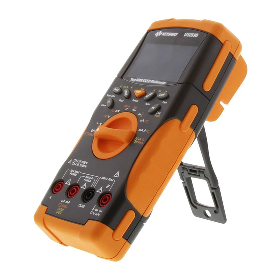
Page 26: Adjusting The Tilt-Stand
Getting Started Adjusting the tilt-stand To adjust the multimeter to a 60° standing position, pull the tilt-stand outward to its maximum reach. IR-USB cable To PC (host) Tilt-stand at 60° Figure 1-1 Tilt-stand at 60° Keysight U1253B User’s and Service Guide... -
Page 27: Figure 1-2 Tilt-Stand At
2 Flip the now detached stand over so that its inner surface is facing the multimeter as opposed to facing you. 3 Press the stand down into its hinge in an upright position. Keysight U1253B User’s and Service Guide... -
Page 28: Figure 1-1 Tilt-Stand At
4. Re-attach the tilt-stand to an upright 3. Flip the tilt-stand over until this sid position of the stand is facing the multimeter as opposed to facing you Figure 1-3 Tilt-stand at hanging position Keysight U1253B User’s and Service Guide... -
Page 29: The Front Panel At A Glance
Getting Started The front panel at a glance Display Keypad Rotary switch Terminal connectors Figure 1-4 U1253B front panel Keysight U1253B User’s and Service Guide... -
Page 30: The Rear Panel At A Glance
Getting Started The rear panel at a glance IR communication port Test probe holders Tilt-stand Battery access cover Figure 1-5 Rear panel Keysight U1253B User’s and Service Guide... -
Page 31: The Rotary Switch At A Glance
DC μA, AC μA, or AC + DC μA DC mA, DC A, AC mA, AC A, AC + DC mA, or AC + DC A Square wave output, duty cycle, or pulse width output Keysight U1253B User’s and Service Guide... -
Page 32: The Keypad At A Glance
Turning the rotary switch to another position resets the current operation of the key. Figure 1-7 shows the keypad of the U1253B. Figure 1-7 U1253B keypad Keysight U1253B User’s and Service Guide... - Page 33 1 second to exit this mode. The saved relative value will be displayed for 3 seconds. – Press while the relative value ( ) is being displayed to cancel the Null function. Keysight U1253B User’s and Service Guide...
-
Page 34: Table 1-2 Keypad Descriptions And Functions
Hold, Null, Dynamic Recording, 1 ms Peak Hold, dual-combination displays (except when the rotary and dual display modes. switch is at the position, or when the multimeter is in 1 ms Peak Hold or Dynamic Recording mode) Keysight U1253B User’s and Service Guide... - Page 35 For pulse width and duty cycle measurements, press to switch between positive and negative edge trigger. When the multimeter is in Peak or Dynamic Recording mode, press restart the 1 ms Peak Hold or Dynamic Recording mode. Keysight U1253B User’s and Service Guide...
-
Page 36: The Display At A Glance
– Negative slope for pulse width (ms) and duty cycle (%) measurements – Capacitor is discharging (during capacitance measurement) Low battery indication (alternating between these two symbols) Auto Power-Off enabled Refresh (auto) Hold Trigger (manual) Hold Keysight U1253B User’s and Service Guide... - Page 37 Dynamic Recording mode: Average value on primary display 1 ms Peak Hold mode: Positive peak value on primary display 1 ms Peak Hold mode: Negative peak value on primary display Hazardous voltage annunciator for measuring voltage ≥ 30 V or Overload Keysight U1253B User’s and Service Guide...
-
Page 38: Table 1-4 Primary Display Symbols
Decibel unit relative to 1 V Frequency units: Hz, kHz, MHz Resistance units: Ω, kΩ, MΩ Conductance unit: nS Voltage units: mV, V Current units: μA, mA, A Capacitance units: nF, μF, mF Celsius temperature unit Fahrenheit temperature unit Keysight U1253B User’s and Service Guide... - Page 39 Pulse width unit Percentage scale readout based on DC 0 mA to 20 mA Percentage scale readout based on DC 4 mA to 20 mA Reference impedance for the dBm unit Scale of bar graph Keysight U1253B User’s and Service Guide...
-
Page 40: Table 1-5 Secondary Display Symbols
Voltage units: mV, V Current units: μA, mA, A Conductance unit: nS Capacitance units: nF, μF, mF Celsius ambient temperature unit Fahrenheit ambient temperature unit No ambient temperature compensation; just thermocouple measurement Pulse width unit Bias display Keysight U1253B User’s and Service Guide... -
Page 41: Table 1-6 Analog Bar Range And Counts
Each segment represents 2000 or 400 counts depending on the range indicated on the peak bar graph. See the following table. Table 1-6 Analog bar range and counts Range Counts/segments Used for the function 2000 V, A, Ω, nS, Diode V, A, Capacitance Keysight U1253B User’s and Service Guide... -
Page 42: Selecting Display With The Shift Button
(AC+DC voltage) AC+DC V DC mV AC mV (AC+DC voltage) AC+DC mV Ω Ω (Audible) (Resistance) Diode (Diode Test & Frequency) Capacitance Temperature (Capacitance & Temperature) DC μA AC μA (AC+DC current) AC+DC μA Keysight U1253B User’s and Service Guide... - Page 43 Pulse width (ms) Notes for selecting d isplay with SHIFT button: [a] Depends on the relevant setting in the Setup mode. [b] Press for more than 1 second to return to AC V measurement only. Keysight U1253B User’s and Service Guide...
-
Page 44: Selecting Display With The Dual Button
Hz (DC coupling) DC mV dBm or dBV (Default is DC voltage) DC mV AC mV AC mV Hz (AC coupling) AC mV dBm or dBV (Press to select AC voltage) AC mV DC mV Keysight U1253B User’s and Service Guide... - Page 45 AC+DC current) AC+DC mA DC mA DC A Hz (DC coupling) (Default is DC current) DC A AC A AC A Hz (AC coupling) (Press to select AC current) AC A DC A Keysight U1253B User’s and Service Guide...
- Page 46 Ambient temperature in ºC or ºF is displayed in upper-right corner. Select 0 ºC compensation by pressing Notes for selecting d isplay with DUAL button: [a] Depends the relevant setting in Setup mode. Keysight U1253B User’s and Service Guide...
-
Page 47: Selecting Display With The Hz Button
AC+DC voltage) Duty cycle (%) Frequency (Hz) Pulse width (ms) DC mV (Default is DC voltage) Duty cycle (%) Frequency (Hz) Pulse width (ms) AC mV (Press to select AC voltage) Duty cycle (%) Keysight U1253B User’s and Service Guide... - Page 48 Pulse width (ms) AC+DC mA (Press twice to select AC+DC current) Duty cycle (%) Frequency (Hz) Pulse width (ms) Hz (Frequency counter) Pulse width (ms) (Only applicable for Divide-1 input) Frequency (Hz) Duty cycle (%) Keysight U1253B User’s and Service Guide...
-
Page 49: The Terminals At A Glance
Getting Started The terminals at a glance To avoid damaging the multimeter, do not exceed the rated input limit. CAUTION Figure 1-8 Connector terminals Keysight U1253B User’s and Service Guide... -
Page 50: Table 1-10 Terminal Connections For Different Measurement Functions
Rotary switch position Input terminals Overload protection 1000 Vrms 1000 Vrms for short circuit <0.3 A 440 mA/1000 V, 30 kA μA.mA fast-acting fuse 11 A/1000 V, 30kA fast-acting fuse 440 mA/1000 V fast-acting fuse Keysight U1253B User’s and Service Guide... -
Page 51: Making Measurements
Keysight U1253B True RMS OLED Multimeter User’s and Service Guide Making Measurements Understanding The Measurement Instructions Measuring Voltage Measuring Current Frequency Counter Measuring Resistance, Conductance, and Testing Continuity Testing Diodes Measuring Capacitance Measuring Temperature Alerts and Warning During Measurement This chapter contains information on how to make measurements using the... -
Page 52: Understanding The Measurement Instructions
Probe the test points Read the results on the display Measuring Voltage The U1253B true RMS OLED multimeter returns an accurate RMS reading not only for sine waves, but also other AC signals such as square, triangle, and staircase waves. -
Page 53: Measuring Ac Voltage
See Table 1-8 “Selecting display with the Dual button” on page 44 for a list of dual measurements available. – Press and hold for more than 1 second to exit dual display mode. Keysight U1253B User’s and Service Guide... -
Page 54: Measuring Dc Voltage
– To avoid possible electric shock or personal injury, enable the Low Pass Filter to verify the presence of hazardous DC voltages. Displayed DC voltage values can be influenced by high frequency AC components and must be filtered to assure an accurate reading. Keysight U1253B User’s and Service Guide... -
Page 55: Figure 2-2 Measuring Dc Voltage
Making Measurements Red Lead Black Lead Figure 2-2 Measuring DC voltage Keysight U1253B User’s and Service Guide... -
Page 56: Measuring Ac And Dc Signals
DC measurement by ensuring that the input protection circuits are not activated. – Press to cycle through the available dual display combinations. NOTE Dual Exit – Press to enable the frequency test mode for voltage measurements. “Frequency Counter” on page 62 to learn more. Keysight U1253B User’s and Service Guide... -
Page 57: Measuring Current
Filter is enabled (refer to “Setting the Filter” page 144). – For measuring AC current signals with a DC offset, refer to “Measuring AC and DC Signals” on page 56. Keysight U1253B User’s and Service Guide... -
Page 58: Figure 2-3 Measuring Μa And Ma Current
Making Measurements Black Lead Red Lead Figure 2-3 Measuring μA and mA current Keysight U1253B User’s and Service Guide... -
Page 59: Percentage Scale Of 4 Ma To 20 Ma
– The percentage scale for 4 mA to 20 mA or 0 mA to 20 mA is calculated using its corresponding DC mA measurement. The U1253B will automatically optimize the best resolution according to Table 2-2 below. -
Page 60: Figure 2-4 Measurement Scale Of 4 Ma To 20 Ma
Making Measurements Black Lead Red Lead Figure 2-4 Measurement scale of 4 mA to 20 mA Keysight U1253B User’s and Service Guide... -
Page 61: A (Ampere) Measurement
Connect the red and black test leads to 10 A input terminals A (red) and COM NOTE (black) respectively. The multimeter is set to measurement automatically when the red test lead is plugged into the A (red) terminal. Black Lead Red Lead Figure 2-5 A (ampere) current measurement Keysight U1253B User’s and Service Guide... -
Page 62: Frequency Counter
– The signal is out of range if the reading is still unstable after the above step has been performed. – Press to scroll through the pulse width (ms), duty cycle (%), and frequency (Hz) measurements. Keysight U1253B User’s and Service Guide... -
Page 63: Figure 2-6 Measuring Frequency
Making Measurements Press Range Red Lead Black Lead Figure 2-6 Measuring frequency Keysight U1253B User’s and Service Guide... -
Page 64: Measuring Resistance, Conductance, And Testing Continuity
The resultant displayed measurement corrects this offset, giving a more accurate resistance measurement. Keysight U1253B User’s and Service Guide... -
Page 65: Figure 2-7 Type Of Display When Smart Ω Is Enabled
Smart Ω feature. The measurement time increases when Smart Ω is enabled. NOTE Bias display Press Press Leak display Figure 2-7 Type of display when Smart Ω is enabled Keysight U1253B User’s and Service Guide... -
Page 66: Figure 2-8 Measuring Resistance
Making Measurements Red Lead Black Lead Figure 2-8 Measuring resistance Keysight U1253B User’s and Service Guide... -
Page 67: Figure 2-9 Resistance, Audible Continuity, And Conductance
Making Measurements Resistance Press Shift Audible continuity Press Shift Press Shift Conductance Figure 2-9 Resistance, audible continuity, and conductance tests Keysight U1253B User’s and Service Guide... -
Page 68: Table 2-3 Audible Continuity Measurement Range
< 10 MΩ When testing continuity, you can choose to test either short continuity or open NOTE continuity. – By default, the multimeter is set to short continuity. – Press to select open continuity. Keysight U1253B User’s and Service Guide... -
Page 69: Figure 2-10 Short Continuity And Open Continuity Test
100 GΩ. As high-resistance readings are susceptible to noise, you can capture average readings using the Dynamic Recording mode. Refer to the section “Dynamic Recording” on page 84 for more information. Keysight U1253B User’s and Service Guide... -
Page 70: Figure 2-11 Conductance Measurement
Making Measurements Red Lead Black Lead Figure 2-11 Conductance measurement Keysight U1253B User’s and Service Guide... -
Page 71: Testing Diodes
– A diode is considered shorted if the multimeter displays approximately 0 V in both forward and reverse bias modes, and the multimeter beeps continuously. – A diode is considered open if the multimeter displays “OL” in both forward and reverse bias modes. Keysight U1253B User’s and Service Guide... -
Page 72: Figure 2-12 Measuring The Forward Bias Of A Diode
Making Measurements Red Lead Black Lead Figure 2-12 Measuring the forward bias of a diode Keysight U1253B User’s and Service Guide... -
Page 73: Figure 2-13 Measuring The Reverse Bias Of A Diode
Making Measurements Red Lead Black Lead Figure 2-13 Measuring the reverse bias of a diode Keysight U1253B User’s and Service Guide... -
Page 74: Measuring Capacitance
Use the DC voltage function in order to confirm that a capacitor has fully discharged. The U1253B true RMS OLED multimeter calculates capacitance by charging a capacitor with a known current for a period of time, measuring the voltage and then calculating the capacitance. -
Page 75: Figure 2-14 Capacitance Measurements
Making Measurements Red Lead Black Lead Figure 2-14 Capacitance measurements Keysight U1253B User’s and Service Guide... -
Page 76: Measuring Temperature
7 For quick measurement, use the 0 °C compensation to view the temperature variation of the thermocouple sensor. The 0 °C compensation assists you in measuring relative temperature immediately. Keysight U1253B User’s and Service Guide... -
Page 77: Figure 2-15 Connecting The Thermal Probe Into The Non-Compensation Transfer Adapter
Making Measurements Figure 2-15 Connecting the thermal probe into the non-compensation transfer adapter Figure 2-16 Connecting the probe with adapter into the multimeter Keysight U1253B User’s and Service Guide... - Page 78 3 After a constant reading is obtained, press to set the reading as the relative reference temperature. 4 Touch the surface to be measured with the thermocouple probe. 5 Read the display for the relative temperature. Keysight U1253B User’s and Service Guide...
-
Page 79: Figure 2-17 Surface Temperature Measurement
Making Measurements Press Dual Figure 2-17 Surface temperature measurement Keysight U1253B User’s and Service Guide... -
Page 80: Alerts And Warning During Measurement
30 V in all three DC V, AC V, and AC+DC V measurement modes. For a manually selected measurement range, when the measured value is outside the range, the display will indicate OL. Keysight U1253B User’s and Service Guide... -
Page 81: Input Warning
A warning message Error ON A INPUT will be displayed until the test lead is removed from the A input terminal. Refer to Figure 2-18. Figure 2-18 Input terminal warning Keysight U1253B User’s and Service Guide... -
Page 82: Charge Terminal Alert
5 V and the rotary switch is not set to the corresponding position. A warning message Error ON mA INPUT will be displayed until the lead is removed from the input terminal. Refer to Figure 2-19 below. Figure 2-19 Charge terminal alert Keysight U1253B User’s and Service Guide... -
Page 83: Functions And Features
Keysight U1253B True RMS OLED Multimeter User’s and Service Guide Functions and Features Dynamic Recording Data Hold (Trigger Hold) Refresh Hold Null (Relative) Decibel Display 1 ms Peak Hold Data Logging Square Wave Output Remote Communication This chapter contains information on the functions and features available for the... -
Page 84: Dynamic Recording
– The average value is the true average of all measured values taken in the Dynamic recording mode. If an overload is recorded, the averaging function will stop and the average value becomes “OL” (overload). Auto Power Off is disabled in Dynamic Recording mode. Keysight U1253B User’s and Service Guide... -
Page 85: Figure 3-1 Dynamic Recording Mode Operation
Press Max Min for > 1 sec. Or Press for > 1 sec. Press Max Min Press Max Min for > 1 sec. Or Press for > 1 sec. Figure 3-1 Dynamic recording mode operation Keysight U1253B User’s and Service Guide... -
Page 86: Data Hold (Trigger Hold)
3 While in the Data Hold mode, you may press to switch between DC, AC, and AC+DC measurements. 4 Press and hold for more than 1 second to quit the data hold function. Keysight U1253B User’s and Service Guide... -
Page 87: Figure 3-2 Data Hold Mode Operation
Functions and Features Press Hold Press Shift Press Press Reading Reading Hold Hold (“T” flashes) (“T” flashes) Updated Updated Figure 3-2 Data hold mode operation Keysight U1253B User’s and Service Guide... -
Page 88: Refresh Hold
4 Press again to disable this function. You may also press for more than 1 second to quit the Refresh Hold function. Keysight U1253B User’s and Service Guide... -
Page 89: Figure 3-3 Refresh Hold Mode Operation
– For resistance and diode measurements, the held value will not be updated if the reading is “OL” (open state). – For all types of measurement, the held value will not be updated until the reading has reached a stable state. Keysight U1253B User’s and Service Guide... -
Page 90: Null (Relative)
Use the Null function to zero-adjust the display. – In DC voltage measurement mode, thermal effects will influence the accuracy. Short the test leads and press once the displayed value is stable to zero-adjust the display. Keysight U1253B User’s and Service Guide... -
Page 91: Figure 3-4 Null (Relative) Mode Operation
Functions and Features Press Null Press Null while O’BASE is being displayed to exit this mode Auto-return Press after 3 seconds Null Figure 3-4 Null (relative) mode operation Keysight U1253B User’s and Service Guide... -
Page 92: Decibel Display
The voltage measurement is indicated on the secondary display. 2 Press for more than 1 second to exit this mode. [1] Depends on configuration in Setup mode. Keysight U1253B User’s and Service Guide... -
Page 93: Figure 3-5 Dbm Display Mode Operation
Functions and Features Press Dual Press Dual for > 1 sec. Press Press Dual Dual Figure 3-5 dBm display mode operation Keysight U1253B User’s and Service Guide... -
Page 94: Figure 3-6 Dbv Display Mode Operation
Functions and Features Press Dual Press Dual for > 1 sec. Press Press Dual Dual Figure 3-6 dBV display mode operation Keysight U1253B User’s and Service Guide... -
Page 95: Ms Peak Hold
– If you need to restart peak recording without changing the range, press 3 Press and hold for more than 1 second to exit this mode. 4 In the measurement example shown in Figure 3-7 on page 96, the crest factor will be 2.2669/1.6032 = 1.414. Keysight U1253B User’s and Service Guide... -
Page 96: Figure 3-7 1 Ms Peak Hold Mode Operation
Start to capture to reset Press Max Min Press Press Range Hold (Note: pressing Hold when in Negative P-HOLD– will change the display into Positive P-HOLD+.) Figure 3-7 1 ms peak hold mode operation Keysight U1253B User’s and Service Guide... -
Page 97: Data Logging
The and the logging index will be displayed for 3 seconds. 2 Press and hold again for the next value that you would like to save into the memory. Keysight U1253B User’s and Service Guide... -
Page 98: Figure 3-8 Manual (Hand) Logging Mode Operation
The maximum number of readings that can be stored is 100 entries. When the NOTE 100 entries are all occupied, the logging index will indicate “Full”, as shown in Figure 3-9. Press Log for > 1 sec. Auto-return after 3 seconds Figure 3-9 Full log Keysight U1253B User’s and Service Guide... -
Page 99: Interval Logging
When interval (time) logging is running, all keypad operations are disabled, NOTE except for Log, which, when pressed for longer than 1 second, will exit this mode. Furthermore, Auto Power Off is disabled during interval logging. Keysight U1253B User’s and Service Guide... -
Page 100: Figure 3-10 Interval (Time) Logging Mode Operation
Press Log for > 1 sec. After first interval Press Log for > 1 sec. Press Log for > 1 sec. Stop logging After last interval Last interval Figure 3-10 Interval (time) logging mode operation Keysight U1253B User’s and Service Guide... -
Page 101: Reviewing Logged Data
4 Press for more than 1 second at the respective Log Review mode to clear logged data. 5 Press for more than 1 second to stop logging and exit this mode. Keysight U1253B User’s and Service Guide... -
Page 102: Figure 3-11 Log Review Mode Operation
Press Press Press Press Press Press Press Log for > 1 sec. Press Log for > 1 sec. to clear all manual logs to clear all interval logs Figure 3-11 Log review mode operation Keysight U1253B User’s and Service Guide... -
Page 103: Square Wave Output
Functions and Features Square Wave Output The U1253B true RMS OLED multimeter’s square wave output can be used to generate a PWM (pulse width modulation) output or provide a synchronous clock source (baud rate generator). You can also use this function to check and calibrate flow-meter displays, counters, tachometers, oscilloscopes, frequency converters, frequency transmitters, and other frequency input devices. -
Page 104: Figure 3-12 Frequency Adjustment For Square Wave Output
Functions and Features Press Press Press Press Figure 3-12 Frequency adjustment for square wave output Keysight U1253B User’s and Service Guide... -
Page 105: Figure 3-13 Duty Cycle Adjustment For Square Wave Output
The duty cycle can be stepped through 256 steps, with each step equivalent to 0.390625%. The best resolution the display can offer is 0.001%. Press Press Press Press Press Press Figure 3-13 Duty cycle adjustment for square wave output Keysight U1253B User’s and Service Guide... -
Page 106: Figure 3-14 Pulse Width Adjustment For Square Wave Output
256 steps, with each step equivalent to 1/(256 × frequency). The displayed pulse width will be automatically adjusted to 5 digits (ranging from 9.9999 to 9999.9 ms). Press Press Press Press Press Press Figure 3-14 Pulse wid th adjustment for square wave output Keysight U1253B User’s and Service Guide... -
Page 107: Remote Communication
For details on performing PC to meter remote communication click on Help after launching the Keysight GUI Data Logger Software or refer to the GUI Data Logger Quick Start Guide (U1251-90003) for more information. Connect to PC Figure 3-15 Cable connection for remote communication Keysight U1253B User’s and Service Guide... - Page 108 Functions and Features THIS PAGE HAS BEEN INTENTIONALLY LEFT BLANK. Keysight U1253B User’s and Service Guide...
-
Page 109: Changing The Default Settings
User’s and Service Guide Changing the Default Settings Selecting Setup Mode Default Factory Settings and Available Setting Options This chapter will show you how to change the default factory settings of the U1253B true RMS OLED multimeter and other available setting options. -
Page 110: Selecting Setup Mode
Press to exit EDIT mode without saving the changes. iv Press to save the changes you have made and exit the EDIT mode. 4 Press for more than 1 second to exit Setup mode. Keysight U1253B User’s and Service Guide... -
Page 111: Default Factory Settings And Available Setting Options
– Available options: dBm, dBV, or OFF. – Select OFF to disable this function for normal operation. dBm-R 50 Ω Reference impedance value for dBm measurement. Select a value within the range of 1 Ω to 9999 Ω. Keysight U1253B User’s and Service Guide... - Page 112 – To disable this function, set all digits to zero (“OFF” will be indicated). BACKLIT HIGH Default power-on backlight brightness level. Available options: HIGH, MEDIUM, or LOW. MELODY FACTORY Power-on melody. Available options: FACTORY, USER, or OFF. GREETING FACTORY Power-on greeting. Available options: FACTORY, USER, or OFF. Keysight U1253B User’s and Service Guide...
- Page 113 BATTERY 7.2 V Battery type used for the multimeter. Available options: 7.2 V or 8.4 V. DC FILTER Filter for DC voltage or DC current measurement. Available options: OFF or ON. Keysight U1253B User’s and Service Guide...
-
Page 114: Figure 4-1 Setup Menu Screens
Changing the Default Settings Figure 4-1 Setup menu screens Keysight U1253B User’s and Service Guide... -
Page 115: Setting Data Hold/Refresh Hold Mode
(automatic trigger). Once the variation of measured values exceeds this value (which is the variation count), the Refresh Hold will be ready to trigger and hold a new value. Figure 4-2 Data Hold/Refresh Hold setup Keysight U1253B User’s and Service Guide... -
Page 116: Setting Data Logging Mode
(time) data logging. Refer to Figure 4-3 below. Figure 4-3 Data logging setup 2 For interval (time) data logging, set the LOG TIME within the range of 0001 second to 9999 seconds to specify the data logging interval. Keysight U1253B User’s and Service Guide... -
Page 117: Figure 4-4 Log Time Setup For Interval (Time) Logging
Press to go to the digit you want to edit Press Hz to save and exit or press Esc to exit without saving Figure 4-4 Log time setup for interval (time) logging Keysight U1253B User’s and Service Guide... -
Page 118: Setting Db Measurement
The decibel unit can be disabled by setting this to “OFF”. The available options are dBm, dBV, and OFF. For dBm measurement, the reference impedance can be set by the “dBm-R” menu item. Figure 4-5 Decibel measurement setup Keysight U1253B User’s and Service Guide... -
Page 119: Setting Reference Impedance For Dbm Measurement
Press to go to the digit you want to edit Press Hz to save and exit or press Esc to exit without saving Figure 4-6 Setting up the reference impedance for dBm unit Keysight U1253B User’s and Service Guide... -
Page 120: Setting Thermocouple Types
1 Celsius only: °C single display. 2 Celsius/Fahrenheit: °C/°F dual display; °C on primary, and °F on secondary. 3 Fahrenheit only: °F single display. 4 Fahrenheit/Celsius: °F/°C dual display; °F on primary, and °C on secondary. Keysight U1253B User’s and Service Guide... -
Page 121: Figure 4-8 Temperature Unit Setup
Press to change the unit Press to change the unit Press to change the unit Press Hz to save and exit or press Esc to exit without saving Figure 4-8 Temperature unit setup Keysight U1253B User’s and Service Guide... -
Page 122: Setting Percentage Scale Readout
“OFF”. Press Hz to edit Press to configure Press to configure Press Hz to save and exit or press Esc to exit without saving Figure 4-9 Setting up percentage scale readout Keysight U1253B User’s and Service Guide... -
Page 123: Sound Setting For Continuity Test
Press Hz to edit Press to switch between SINGLE, OFF and TONE Press Hz to save and exit or press Esc to exit without saving Figure 4-10 Choosing the sound used in continuity test Keysight U1253B User’s and Service Guide... -
Page 124: Setting Minimum Measurable Frequency
Press to choose the value Press to choose the value Press to choose the value Press Hz to save and exit or press Esc to exit without saving Figure 4-11 Minimum frequency setup Keysight U1253B User’s and Service Guide... -
Page 125: Setting Beep Frequency
Press to choose the value Press to choose the value Press to choose the value Press Hz to save and exit or press Esc to exit without saving Figure 4-12 Beep frequency setup Keysight U1253B User’s and Service Guide... -
Page 126: Setting Auto Power Off Mode
– To disable APO, select OFF. When APO is disabled, the annunciator will be turned off. The multimeter will remain on until you manually turn the rotary switch to the OFF position. Keysight U1253B User’s and Service Guide... -
Page 127: Figure 4-13 Automatic Power Saving Setup
APO to “OFF” Press to go to the digit you want to edit Press Hz to save and exit or press Esc to exit without saving Figure 4-13 Automatic power saving setup Keysight U1253B User’s and Service Guide... -
Page 128: Setting Power-On Backlight Brightness Level
Press Hz to save and exit or press Esc to exit without saving Figure 4-14 Power-on backlight setup While using the multimeter, you may adjust the brightness at any time by pressing button. Keysight U1253B User’s and Service Guide... -
Page 129: Setting The Power-On Melody
FACTORY, USER, or OFF. The USER setting is factory reserved. Press Hz to edit Press to toggle between Press Hz to save and exit these options or press ESC to exit without saving Figure 4-16 Power-on greeting setup Keysight U1253B User’s and Service Guide... -
Page 130: Setting Baud Rate
Press to choose the value Press to choose the value Press Hz to save and exit or press Esc to exit without saving Figure 4-17 Baud rate setup for remote control Keysight U1253B User’s and Service Guide... -
Page 131: Setting Data Bits
8 or 7 bits. The number of stop bit is always 1, and this cannot be changed. Press Hz to edit Press to switch between 7 and 8 Press Hz to save and exit or press Esc to exit without saving Figure 4-18 Data bits setup for remote control Keysight U1253B User’s and Service Guide... -
Page 132: Setting Parity Check
ODD, or EVEN. Press Hz to edit Press to configure Press to configure Press Hz to save and exit or press Esc to exit without saving Figure 4-19 Parity check setup for remote control Keysight U1253B User’s and Service Guide... -
Page 133: Setting Echo Mode
Press Hz to edit Press to switch between OFF and ON Press Hz to save and exit or press Esc to exit without saving Figure 4-20 Echo mode setup for remote control Keysight U1253B User’s and Service Guide... -
Page 134: Setting Print Mode
Press Hz to edit Press to switch between OFF and ON Press Hz to save and exit or press Esc to exit without saving Figure 4-21 Print mode setup for remote control Keysight U1253B User’s and Service Guide... -
Page 135: Revision
Changing the Default Settings Revision The revision number of the firmware will be indicated. Figure 4-22 Revision number Serial number The last 8 digits of the serial number will be indicated. Figure 4-23 Serial number Keysight U1253B User’s and Service Guide... -
Page 136: Voltage Alert
Press to edit the value Press to go to the digit you want to edit Press Hz to save and exit or press Esc to exit without saving Figure 4-24 Voltage alert setup Keysight U1253B User’s and Service Guide... -
Page 137: M-Initial
As example, when you turn the rotary switch to the position, the initial measurement function is diode measurement according to the default factory setting. In order to choose the frequency counter function you require, press the button. Keysight U1253B User’s and Service Guide... -
Page 138: Figure 4-25 Setting Initial Measurement Functions
In the INIT pages, you may define your preferred initial measurement functions. Please refer to Figure 4-26. Press to navigate between the two INIT pages. Press to choose which initial function you want to change. Keysight U1253B User’s and Service Guide... -
Page 139: Figure 4-26 Navigating Between The Initial Functions
For example, Figure 4-27 below shows the initial measurement function of the F5 position changed from DIODE to FC (frequency counter). Edit F1 initial range and F5 initial function Figure 4-27 Editing initial measurement function/range Keysight U1253B User’s and Service Guide... -
Page 140: Figure 4-28 Editing Initial Measurement Function/Range And Initial Output Values
EDIT mode. If you reset the multimeter to its default factory settings (see “Returning to default factory settings” on page 142), your settings for M-INITIAL will also revert to the factory defaults. Keysight U1253B User’s and Service Guide... -
Page 141: Smooth Refresh Rate
The default option is NORMAL. Press Hz to edit Press to configure Press to configure Press Hz to save and exit or press Esc to exit without saving Figure 4-29 Refresh rate for primary display readings Keysight U1253B User’s and Service Guide... -
Page 142: Returning To Default Factory Settings
1 second to reset to default factory settings (all except the temperature setting). – The Reset menu item automatically reverts to menu page 1 after a reset has taken place. Figure 4-30 Resetting to default factory settings Keysight U1253B User’s and Service Guide... -
Page 143: Setting The Battery Type
The battery type for the multimeter can be set to either 7.2 V or 8.4 V. Press Hz to edit Press to switch between 7.2 V and 8.4 V Press Hz to save and exit or press Esc to exit without saving Figure 4-31 Battery type selection Keysight U1253B User’s and Service Guide... -
Page 144: Setting The Filter
Filter – When the Filter is enabled, the measurement speed may decrease during DC NOTE voltage measurement. – During AC or Hz measurement (on primary or secondary display), DC filter will be automatically disabled. Keysight U1253B User’s and Service Guide... -
Page 145: Maintenance
Keysight U1253B True RMS OLED Multimeter User’s and Service Guide Maintenance Introduction Replaceable Parts This chapter will help you to troubleshoot if the U1253B true RMS OLED multimeter malfunctions. -
Page 146: Introduction
3 Wipe the case with a damp cloth and mild detergent — do not use abrasives or solvents. Wipe the contacts in each terminal with a clean cotton swab moistened with alcohol. Keysight U1253B User’s and Service Guide... -
Page 147: Battery Replacement
“Charging the battery” on page 150. The procedures for battery replacement are as follows: The U1253B comes supplied with a 9 V Ni-MH rechargeable battery, 8.4 V NOTE nominal voltage. Figure 5-1 9 V rectangular battery Keysight U1253B User’s and Service Guide... -
Page 148: Figure 5-2 Rear Panel Of The Keysight U1253B True Rms Oled
1 On the rear panel, turn the screw on the battery cover counterclockwise from the LOCK position to OPEN. Figure 5-2 Rear panel of the Keysight U1253B True RMS OLED Multimeter 2 Slide the battery cover down. 3 Lift the battery cover up. -
Page 149: Storage Considerations
Maintenance List of compatible batteries for the Keysight U1253B: NOTE – 9 V Alkaline non-chargeable battery (ANSI/NEDA 1604A or IEC 6LR61) – 9 V Carbon-zinc non-chargeable battery (ANSI/NEDA 1604D or IEC6F22) – 9 V size 300 mAH Ni-MH rechargeable battery, 7.2 V nominal voltage –... -
Page 150: Charging The Battery
Upon initial use (or after a prolonged storage period), the battery may require three to four charge/discharge cycles before achieving maximum capacity. To discharge, simply run the multimeter under the battery's power until it shuts down or the low battery warning appears. Keysight U1253B User’s and Service Guide... - Page 151 The multimeter will output short single-tone sounds to remind you to charge the battery. Press to start charging the battery, or the multimeter will automatically start charging after10 seconds. It is recommended not to charge the battery if the battery capacity is over 90%. Keysight U1253B User’s and Service Guide...
-
Page 152: Figure 5-3 Self-Testing Time Display
This self-test will take 3 minutes. Avoid pressing any of the push-buttons during the self-test. If there is any error, the multimeter will display error messages as shown in Table 5-2 on page 153. Keysight U1253B User’s and Service Guide... -
Page 153: Figure 5-4 Performing Self-Test
3 Battery is fully charged CHARGE ERROR 1 If charging battery more than 12 V or less than 5 V 2 In 3 minutes, if the battery voltage does not go upwards then charge error Keysight U1253B User’s and Service Guide... -
Page 154: Figure 5-5 Charging Mode
220 minutes. The display will count down the charging time. When battery charging is in progress, none of the push-buttons can be operated. To avoid overcharging the battery, the charging may be stopped with an error message during the charging process. Keysight U1253B User’s and Service Guide... -
Page 155: Figure 5-6 Fully Charged And In The Trickle State
Do not turn the rotary switch before removing the adapter from the CAUTION terminals. Applicable for U1253B with Firmware version 3.06 and above. NOTE In order to comply with US DOE & CA CEC regulation enforced on January 1, 2017, the trickle charge feature as described in step 8 has been disabled. -
Page 156: Figure 5-7 Battery Charging Procedures
Maintenance Press Shift or after time out to start charging Over limit level ERROR Charge error Battery can be charged Fully charged or time out Figure 5-7 Battery charging procedures Keysight U1253B User’s and Service Guide... -
Page 157: Fuse Checking Procedure
Follow the instructions below to test the fuses inside the multimeter. Refer to Figure 5-9 for the respective positions of Fuse 1 and Fuse 2. 1 Set the rotary switch to 2 Connect the red test lead to the input terminal Figure 5-8 Fuse checking procedures Keysight U1253B User’s and Service Guide... - Page 158 5 Observe the reading on the instrument's display. Refer to Table 5-3 for the possible readings that could appear. 6 Replace the fuse when OL is displayed. Table 5-3 U1253B measurement readings for fuse checking Fuse OK (approximately) Replace fuse Current input terminal Fuse Fuse rating...
-
Page 159: Fuse Replacement
OFF position. 9 Re-fasten the circuit board and the bottom cover. 10 Refer to Table 5-4 on page 160 for the part number, rating, and size of the fuses. Keysight U1253B User’s and Service Guide... -
Page 160: Figure 5-9 Fuse Replacement
Keysight part number Rating Size Type 2110-1400 440 mA/1000 V 10 mm × 35 mm Fast blow fuse 2110-1402 11 A/1000 V 10 mm × 38 mm Fuse 2 Fuse 1 Figure 5-9 Fuse replacement Keysight U1253B User’s and Service Guide... -
Page 161: Troubleshooting
When servicing the instrument, use only the specified replacement parts. Table 5-5 on page 162 will assist you in identifying some basic problems and their solutions. Keysight U1253B User’s and Service Guide... -
Page 162: Table 5-5 Basic Troubleshooting Procedures
– Ensure that the required driver for IR-USB has been installed. Notes for basic troubleshooting proced ures table: [a] Never turn the rotary switch of the multimeter from the OFF position when it is charging. Keysight U1253B User’s and Service Guide... -
Page 163: Replaceable Parts
1 Contact your nearest Keysight Sales Office or Service Center. 2 Identify the parts by the Keysight part number shown in the support parts list. 3 Provide the instrument model number and serial number. Keysight U1253B User’s and Service Guide... - Page 164 Maintenance THIS PAGE HAS BEEN INTENTIONALLY LEFT BLANK. Keysight U1253B User’s and Service Guide...
- Page 165 Keysight U1253B True RMS OLED Multimeter User’s and Service Guide Performance Tests and Calibration Calibration Overview Recommended Test Equipment Basic Operating Tests Test Considerations Performance Verification Tests Calibration Security Adjustment Considerations Calibration From Front Panel This chapter contains the performance test and adjustment procedures.
-
Page 166: Calibration Overview
This manual contains procedures for verifying the instrument performance, as well as procedures for making adjustments where necessary. The performance test procedure verifies that the U1253B true RMS OLED multimeter is operating within its published specifications. The adjustment procedure ensure that the multimeter remains within its specifications until the next calibration. -
Page 167: Calibration Interval
Specifications are only guaranteed within the specified period from the last calibration. Keysight recommends that readjustment should be performed during the calibration process for best performance. This will ensure that the U1253B true RMS OLED multimeter remains within its specifications. This calibration criterion provides the best long-term stability. -
Page 168: Recommended Test Equipment
Table 6-1 Recommended test equipment Application Recommended equipment Recommended accuracy requirements DC voltage Fluke 5520A < 20% of U1253B accuracy spec DC current Fluke 5520A < 20% of U1253B accuracy spec Resistance Fluke 5520A < 20% of U1253B accuracy spec... -
Page 169: Basic Operating Tests
Repair is required if the instrument fails any of these basic operating tests. Testing the display Press and hold the button while turning on the multimeter to view all the OLED pixels. Check for dead pixels. Figure 6-1 Displaying all OLED pixels Keysight U1253B User’s and Service Guide... -
Page 170: Current Terminals Test
A terminal. Before conducting this test, make sure the beep function is not disabled in Setup. NOTE Figure 6-2 Current terminal error message Keysight U1253B User’s and Service Guide... -
Page 171: Charge Terminals Alert Test
Figure 6-3 Charge terminal error message Before conducting this test, make sure the beep function is not disabled in Setup. NOTE Keysight U1253B User’s and Service Guide... -
Page 172: Test Considerations
– Ensure that ambient relative humidity is less than 80%. – Allow a warm-up period of 5 minutes. – Use shielded twisted-pair PTFE-insulated cables to reduce settling and noise errors. Keep the input cables as short as possible. Keysight U1253B User’s and Service Guide... -
Page 173: Performance Verification Tests
(one setting at a time, if more than one setting is listed). 3 Turn the rotary switch of the U1253B true RMS OLED multimeter to the function being tested, and choose the correct range, as specified in the table. - Page 174 Turn the rotary switch to the position 50 V 50 V ± 17.5 mV Press to select DC V measurement 500 V 500 V ± 200 mV 1000 V 1000 V ± 800 mV Keysight U1253B User’s and Service Guide...
- Page 175 ± 75 μV Press to select DC mV measurement 500 mV 500 mV ± 175 μV –500 mV ± 175 μV 1000 mV 1000 mV ± 0.75 mV –1000 mV ± 0.75 mV Keysight U1253B User’s and Service Guide...
- Page 176 ± 505 kΩ 50 MΩ 500 MΩ 450 MΩ ± 36.10 MΩ 50 nS ± 0.6 nS Press to select conductance (nS) 500 nS measurement Diode ± 1 mV Turn the rotary switch to the position Keysight U1253B User’s and Service Guide...
-
Page 177: Table 6-2 Performance Verification Tests
± 0.65 mA 50 mA 50 mA, 1 kHz ± 0.37 mA Press to select AC mA measurement 440 mA 400 mA, 45 Hz ± 3 mA 400 mA, 1 kHz ± 3 mA Keysight U1253B User’s and Service Guide... - Page 178 Turn the rotary switch to the position 4800 Hz @ 50% ± 260 mHz 100 Hz @ 50% ± 0.398% duty cycle 100 Hz @ 25% ± 0.398% 100 Hz @ 75% ± 0.398% Keysight U1253B User’s and Service Guide...
- Page 179 — To perform the measurement, connect one end of the K-type thermocouple (with miniature TC connector on both ends) to the 5520A TC output, and the other end to the multimeter via a TC-to-banana adapter. Allow at least 1 hour for the multimeter to stabilize. Keysight U1253B User’s and Service Guide...
-
Page 180: Calibration Security
Calibration Security A calibration security code is in place to prevent accidental or unauthorized adjustments to the U1253B true RMS OLED multimeter. When you first receive your instrument, it is secured. Before you can adjust the instrument, you must “unsecure” it by entering the correct security code (see the section “Unsecuring... - Page 181 8 If the incorrect security code is entered, an error code will be displayed instead for 3 seconds, after which the Calibration Security Code entry mode will appear again. Please refer to Figure 6-4 on page 182. To secure the instrument again (exit the unsecured mode), press simultaneously. Keysight U1253B User’s and Service Guide...
-
Page 182: Figure 6-4 Unsecuring The Instrument For Calibration
Press Save when done Incorrect security code Security code is correct The word “PASS” appears for 3 seconds, then proceeds to the first calibration item Figure 6-4 Unsecuring the instrument for calibration Keysight U1253B User’s and Service Guide... -
Page 183: Changing Calibration Security Code
(Save) to save the new security code. 5 If the new calibration security code has been successfully stored, the upper left corner of the secondary display will momentarily show the word “PASS”. Please refer to Figure 6-5 on page 184. Keysight U1253B User’s and Service Guide... -
Page 184: Figure 6-5 Changing The Calibration Security Code
Press to edit selected digit Press Save when done New security code is not acceptable New security code is acceptable The word “PASS” appears for 3 seconds Figure 6-5 Changing the calibration security code Keysight U1253B User’s and Service Guide... -
Page 185: Resetting The Security Code To Factory Default
Now the security code has been reset to the factory default, 1234. If you wish to change the security code, refer to the section “Changing Calibration Security Code” on page 183. Make sure you record the new security code. Please refer to Figure 6-6 on page 186. Keysight U1253B User’s and Service Guide... - Page 186 Press Save when done Last 4 digit of serial number is incorrect Last 4 digit of serial number is correct The word “PASS” appears for 3 seconds Figure 6-6 Resetting security code to factory default Keysight U1253B User’s and Service Guide...
-
Page 187: Adjustment Considerations
1 hour with the K-type thermocouple connected between the instrument and the calibration source. Never turn off the instrument during calibration. This may delete the calibration CAUTION memory for the present function. Keysight U1253B User’s and Service Guide... -
Page 188: Valid Adjustment Reference Input Values
0.9 to 1.1 × reference input value 50 V 30.000 V 0.9 to 1.1 × reference input value 500 V 300.00 V 0.9 to 1.1 × reference input value 1000 V 1000.0 V 0.9 to 1.1 × reference input value Keysight U1253B User’s and Service Guide... - Page 189 0.9 to 1.1 × reference input value 500 mA 300.00 mA 0.9 to 1.1 × reference input value 3.000 A 0.9 to 1.1 × reference input value 10 A 10.000 A 0.9 to 1.1 × reference input value Keysight U1253B User’s and Service Guide...
- Page 190 0.9 to 1.1 × reference input value 100 μF 100.00 μF 0.9 to 1.1 × reference input value 1000 μF 1000.0 μF 0.9 to 1.1 × reference input value 10 mF 10.000 mF 0.9 to 1.1 × reference input value Keysight U1253B User’s and Service Guide...
- Page 191 — To perform the adjustment, connect one end of the K-type thermocouple (with miniature TC connector on both ends) to the 5520A TC output, and the other end to the multimeter via a TC-to-banana adapter. Allow at least 1 hour for the multimeter to stabilize. Keysight U1253B User’s and Service Guide...
-
Page 192: Calibration From Front Panel
5 Take note of the new security code (if it has been changed) and the calibration count in the instrument maintenance records. Make sure to quit the adjustment mode before switching off the instrument. NOTE Keysight U1253B User’s and Service Guide... -
Page 193: Calibration Procedures
Performance Tests and Calibration Calibration procedures 1 Turn the rotary switch to the function you wish to calibrate. 2 Unsecure the U1253B true RMS OLED multimeter (refer to “Unsecuring the instrument for calibration” on page 180). 3 After verifying that the security code you entered is correct, the instrument will... - Page 194 9 After calibrating all the functions, press simultaneously to exit calibration mode. 10 Switch off the instrument and then switch it on again. The instrument will be back to normal measurement mode. Refer to Figure 6-7 on page 195. Keysight U1253B User’s and Service Guide...
-
Page 195: Figure 6-7 Typical Calibration Process Flow
Press Save when ready to start calibration Reading out of acceptable range Reading is within acceptable range The word “PASS” appears for 3 seconds, then proceeds to the next calibration item Figure 6-7 Typical calibration process flow Keysight U1253B User’s and Service Guide... -
Page 196: Table 6-4 List Of Calibration Items
1000.0 V 1000 V (done) DC mV Short SHORT Dual banana shorting plug with copper wire 50 mV 30.000 mV 30 mV 500 mV 300.00 mV 300 mV 1000 mV 1000.0 mV 1000 mV (done) Keysight U1253B User’s and Service Guide... - Page 197 300 kΩ 50 kΩ 30.000 kΩ 30 kΩ 5 kΩ 3.0000 kΩ 3 kΩ 500 Ω 300.00 Ω 300 Ω (done) Diode Short SHORT Dual banana shorting plug with copper wire 2.0000 V (done) Keysight U1253B User’s and Service Guide...
- Page 198 30 μA, 1 kHz 30.00 μA (1 kHz) 300 μA, 1 kHz 300.00 μA (1 kHz) 5000 μA 300.0 μA (1 kHz) 300 μA, 1 kHz 3000.0 μA (1 kHz) 3000 μA, 1 kHz (done) Keysight U1253B User’s and Service Guide...
- Page 199 0.3000 A (1 kHz) 0.3 A, 1 kHz 3.0000 A (1 kHz) 3 A, 1 kHz 10 A 3.000 A (1 kHz) 3 A, 1 kHz 10.000 A (1 kHz) 10 A, 1 kHz (done) Keysight U1253B User’s and Service Guide...
-
Page 200: Calibration Count
The calibration count is stored in a nonvolatile EEPROM memory, the contents of which do not change even after the instrument is switched off or after a remote interface reset. Your U1253B true RMS OLED multimeter had been calibrated before leaving the factory. When you receive your multimeter, make sure to read the calibration count and record it for maintenance purpose. -
Page 201: Calibration Error Codes
Calibration error: Serial number invalid. ER004 Calibration error: Calibration aborted. ER005 Calibration error: Value out of range. ER006 Calibration error: Signal measurement out of range. ER007 Calibration error: Frequency out of range. ER008 EEPROM write failure. Keysight U1253B User’s and Service Guide... - Page 202 Performance Tests and Calibration THIS PAGE HAS BEEN INTENTIONALLY LEFT BLANK. Keysight U1253B User’s and Service Guide...
-
Page 203: Specifications
Keysight U1253B True RMS OLED Multimeter User’s and Service Guide Specifications For the characteristics and specifications of the U1253B True RMS OLED Multimeter, refer to the datasheet at http://literature.cdn.keysight.com/litweb/pdf/5989-5509EN.pdf... - Page 204 Specifications THIS PAGE HAS BEEN INTENTIONALLY LEFT BLANK. Keysight U1253B User’s and Service Guide...
- Page 205 This information is subject to change without notice. Always refer to the Keysight website for the latest revision. © Keysight Technologies 2009 - 2017 Edition 19, November 1, 2017 Printed in Malaysia *U1253-90035* U1253-90035 www.keysight.com...
Need help?
Do you have a question about the U1253B and is the answer not in the manual?
Questions and answers