
Related Manuals for Keysight Technologies 34410A


Summary of Contents for Keysight Technologies 34410A
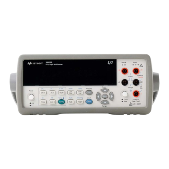
- Page 1 Keysight 34410A/11A 6 ½ Digit Multimeter (includes the L4411A 1U DMM) User’s Guide...
- Page 4 Further, written consent from Keysight Technologies A CAUTION notice denotes a hazard. to the maximum extent permitted as governed by United States and...
- Page 5 II installations for line volt- Return the product to a Keysight Technologies Sales and Service Office for service and repair nals before servicing. Only quali- ages up to 300 VAC. To avoid the to ensure that safety features are maintained.
- Page 6 Current Input Terminal. The current input ("I") The 34410A/11A and L4411A may be used to terminal has a Protection Limit of 3A (rms) make measurements with the HI and LO inputs...
- Page 7 Additional Notices Keysight 34138A Test Lead Set Waste Electrical and Electronic Equipment (WEEE) Directive The Keysight 34410A/11A is provided with 2002/96/EC a Keysight 34138A Test Lead Set, described below. This product complies with the WEEE Directive Test Lead Ratings (2002/96/EC) marking requirement. The affixed...
- Page 8 Declaration of Conformity Declarations of Conformity for this product and for other Keysight products may be downloaded from the Keysight Regulatory Web site: http://regulations.products.keysight.com/DoC/search.htm 34410A/11A/L4411A User’s Guide...
- Page 9 Voltmeter Complete and External Trigger Signals. Synchronize with other instruments in your test system. Note: This manual covers operation of the Keysight 34410A, 34411A, and L4411A 6½ Digit Multimeters. The features described in this manual, except where otherwise noted, apply to each of the multimeters.
- Page 10 The Front Panel at a Glance (34410A/11A) 1 On/Off Switch 8 Exit Key (Auto Range) 2 Measurement Function Keys 9 Shift Key (Local) 3 Configuration Key 10 Menu Navigation Keypad (Range) 4 Second Display Key (Reset) 11 Front/Rear Switch 5 Null Key (Math Functions)
- Page 11 The Rear Panel at a Glance (34410A/11A) 1 Current Input Fuse (front and rear) 2 HI and LO Sense Terminals (4-wire resistance and temperature) 3 HI and LO Input Terminals (voltage, resistance, and other functions) 4 Current Input Terminal (ac current and dc current only)
- Page 12 The Display at a Glance (34410A/11A) Alphanumeric Displays: 1 Primary display line 2 Secondary display line Annunciators: Annunciators: (measurement in progress) 12 Shift (shift key just pressed) 4 Hi-Z (high input impedance, Vdc only) 13 Math (dB or dBm function enabled)
- Page 13 In this chapter you will find a detailed description of the multimeter’s capabilities and operation. This chapter presents both front-panel and remote interface operation of the instrument. Note. Refer to the Keysight 34410A/11A/L4411A Programmer’s Reference help system for a detailed description of the SCPI commands. Remote Interface This chapter describes how to connect the multimeter using a remote interface.
- Page 14 34410A/11A/L4411A User’s Guide...
-
Page 15: Table Of Contents
Keysight 34410A/11A/L4411A 6½ Digit Multimeter User’s Guide Quick Start This chapter gives you a quick overview of the 34410A/11A multimeter’s front panel and basic features. The examples will help you become familiar with your meter, its measuring functions, and basic operation. -
Page 16: Basic Multimeter Operations
Quick Start Basic Multimeter Operations This section introduces the basics of the 34410A/11A multimeter, and how to use it. For basic information unique to the L4411A, refer to the L4411A Getting Started Guide NOT E (p/n L4411-90001). Preparing the Multimeter for Use To verify that your 34410A or 34411A multimeter is ready for use: 1 Check the list of supplied items. -
Page 17: Using The Front Panel (34410A/11A)
Quick Start Using the Front Panel (34410A/11A) This section introduces the 34410A/11A multimeter front panel. Front-Panel Keys The front panel provides keys to select various functions and operations. Pressing a measurement function key (e.g. ) selects that function. Press to enter the configuration menu for the selected measurement function. - Page 18 • If either the ac voltage or ac current measurement function is selected, pressing during front panel measurement operations will increase or decrease the bandwidth setting. • If the frequency/period measurement function is selected, pressing during front panel measurement operations will increase or decrease the gate time setting. 34410A/11A/L4411A User’s Guide...
-
Page 19: Making Basic Measurements (34410A/11A)
Making Basic Measurements (34410A/11A) This section introduces the many types of measurements that you can make with your 34410A/11A multimeter, and how to make connections for each measurement. Most basic measurements can be taken using the factory default settings. A more complete description of all multimeter functions, measurement parameter configuration and remote interface operation is provided in Chapter 2. -
Page 20: To Measure Ac Voltage
Connect test leads as shown: DC Current To Measure AC Current Press to select the ac current function. • Ranges: 100 mA, 1 mA, 10 mA, 100 mA, 1 A, 3 A • AC Technique: true–RMS, ac–coupled 34410A/11A/L4411A User’s Guide... -
Page 21: To Make A 2-Wire Resistance Measurement
3 Connect the probe ends to the test circuit, and measure the corrected resistance value. To Make a 4-wire Resistance Measurement Press to select the 4-wire resistance function. • Ranges: 100Ω, 1 kΩ, 10 kΩ, 100 kΩ, 1 MΩ, 10 MΩ, 100 MΩ, 1 GΩ 34410A/11A/L4411A User’s Guide... -
Page 22: To Measure Frequency
To Measure Period Press to select the frequency function. Then press and select PERIOD from the menu. • Measurement band: 0.33 s to 3.3 µs • Input signal range: 100 mVAC to 750 VAC • Technique: reciprocal counting 34410A/11A/L4411A User’s Guide... -
Page 23: To Measure Capacitance
3 Reconnect the + lead’s probe end to the test circuit, and measure the corrected capacitance value. To Make a 2-Wire Temperature Measurement Press to select the temperature function. Then press and select RTD-2W or THERMISTOR-2W from the menu. • Probe types: 2.2 kΩ, 5 kΩ, 10 kΩ thermistors; 0.00385/°C RTD 34410A/11A/L4411A User’s Guide... -
Page 24: To Make A 4-Wire Temperature Measurement
COMP (RTD probes only), INTEGRATION, UNITS, NULL, and NULL VALUE Connect test leads as shown: Thermistor or RTD All 4-wire temperature measurements are made with auto-zero on. To Test Continuity Press to select the continuity function. • Test current source: 1 mA 34410A/11A/L4411A User’s Guide... -
Page 25: To Check Diodes
Connect test leads as shown: Forward Bias The diode check function is used to indicate correct diode operation; closed–circuit on forward bias and open–circuit on reverse–bias. Other Basics of Operation This section covers basic troubleshooting and general use. 34410A/11A/L4411A User’s Guide... -
Page 26: If The Multimeter Does Not Turn On
Change the voltage setting if it is not correct. The settings are: 100, 120, 220, or 240 Vac (for 230 Vac operation, use the 220 Vac setting). “To Replace the Power-Line Fuse (34410A/11A)” on page 25 if you need to change the line–voltage setting. -
Page 27: To Replace The Power-Line Fuse (34410A/11A)
Quick Start To Replace the Power-Line Fuse (34410A/11A) Remove power cord first. Then follow these steps: Depress tab (1) and pull fuse holder (2) from Remove line-voltage selector from fuse rear panel. holder assembly. Keysight Part Number 2110-0817 (250 mA, 250V, slow-blow, 5x20mm) Rotate line-voltage selector and reinstall so Replace fuse holder assembly in rear panel. -
Page 28: To Adjust The Carrying Handle
Quick Start To Adjust the Carrying Handle To adjust the position, grasp the handle by the sides and pull outward. Then, rotate the handle to the desired position. Bench-Top Viewing Positions Carrying Position 34410A/11A/L4411A User’s Guide... -
Page 29: To Rack Mount The Multimeter (34410A/11A)
Quick Start To Rack Mount the Multimeter (34410A/11A) You can mount the 34410A/11A in a standard 19–inch rack cabinet using the available rack–mount kits. Instructions and mounting hardware are included with each kit. Any Keysight System II (half-width, 2U height) instrument of either the 272.3 mm or the 348.3 mm depth can be rack mounted side–by–side with the 34410A/11A. - Page 30 Quick Start 34410A/11A/L4411A User’s Guide...
- Page 31 To Make a 4-Wire Temperature Measurement To Test Continuity To Check Diodes Other Basics of Operation If the Multimeter Does Not Turn On To Replace the Power-Line Fuse (34410A/11A) To Adjust the Carrying Handle To Rack Mount the Multimeter (34410A/11A) 34410A/11A User’s Guide...
- Page 32 Configuring Frequency and Period Measurements Configuring Temperature Measurements Configuring Capacitance Measurements Continuity and Diode Tests Advanced Configuration Options Multimeter State Storage Accessing Reading Memory Front/Rear Input Terminal Switching (34410A/11A) Multimeter Reset DC Measurements Integration Time and Resolution DC Input Impedance AC Measurements AC Filter Gate Time 34410A/11A/L4411A User’s Guide...
- Page 33 Contents Auto Zero Ranging Null Measurements Miscellaneous Configuration Settings Radix Character (34410A/11A) Thousands Separator (34410A/11A) Beeper (34410A/11A) Math Functions dB Measurements dBm Measurements Using Statistics Limit Testing Triggering the Multimeter Selecting a Trigger Source Auto Triggering (34410A/11A) Single Triggering (34410A/11A)
- Page 34 Web Password Instrument Unexpectedly Goes into Remote Setting up a LAN connection from the Front Panel Setting up a LAN connection from the Remote Interface Keysight 34410A/11A Web Interface Measurement Tutorial DC Measurement Considerations Thermal EMF Errors Loading Errors (dc volts) Noise Rejection Rejecting Power–Line Noise Voltages...
- Page 35 Making High–Speed dc and Resistance Measurements Other Sources of Measurement Error Settling Time Effects Loading Errors (ac volts) Measurements Below Full Scale High–Voltage Self–Heating Errors AC Current Measurement Errors (Burden Voltage) Low–Level Measurement Errors Common Mode Errors Leakage Current Errors 34410A/11A/L4411A User’s Guide...
- Page 36 Frequency and Period Characteristics Capacitance Characteristics Temperature Characteristics Additional 34411A/L4411A Specifications Measurement and System Speeds System Speeds Data From Memory General Specifications (34410A/11A) General Specifications (L4411A) Triggering and Memory Dimensions To Calculate Total Measurement Error Interpreting Accuracy Specifications Transfer Accuracy 24–Hour Accuracy...
-
Page 37: Features And Functions
Configuring Capacitance Measurements 46 Continuity and Diode Tests 47 Advanced Configuration Options 48 Multimeter State Storage 49 Accessing Reading Memory 50 Front/Rear Input Terminal Switching (34410A/11A) 50 Multimeter Reset 51 DC Measurements 52 Integration Time and Resolution 52 DC Input Impedance 54... - Page 38 Features and Functions AC Measurements AC Filter Gate Time Auto Zero Ranging Null Measurements Miscellaneous Configuration Settings Radix Character (34410A/11A) Thousands Separator (34410A/11A) Beeper (34410A/11A) Math Functions dB Measurements dBm Measurements Using Statistics Limit Testing Triggering the Multimeter Selecting a Trigger Source...
-
Page 39: Scpi Commands
Features and Functions SCPI Commands The Keysight 34410A/11A/L4411A complies with the syntax rules and conventions of SCPI (Standard Commands for Programmable Instruments). For complete SCPI command syntax information, refer to the Keysight NOT E 34410A/11A/L4411A Programmer’s Reference Help. This is a standard Windows help system, provided on the Keysight 34410A/11A/L4411A Product Reference CD-ROM that came with your instrument. -
Page 40: Front Panel Features (34410A/11A)
Features and Functions Front Panel Features (34410A/11A) Front Panel Display The Keysight 34410A/11A provides a two–line, alphanumeric display, with annunciators to indicate certain non–default instrument states. Displayed Messages While taking measurements, the primary display line shows the current reading, with units (for example: “-0.001,02 VDC”). -
Page 41: Annunciators
• A measurement is in progress (the “sample annunciator”). • Hi–Z For DC voltage measurements in the 100 mV, 1 V or 10 V ranges, an input impedance of >10 GΩ is configured. 34410A/11A/L4411A User’s Guide... -
Page 42: Second Display Options
Freq AC Voltage Temp Raw Resistance ac voltage of the input waveform actual raw resistance measured across temperature probe and leads • Front Panel Operation: Press 2ND DISPLAY > PK-TO-PK (Where primary function is voltage or current.) 34410A/11A/L4411A User’s Guide... -
Page 43: Front-Panel Display Shortcuts
<feed> ASCII string: DISPlay:WINDow2:TEXT:FEED? Refer to the Keysight 34410A/11A/L4411A Programmer’s Reference Help for a complete description and syntax for these commands. Turning the Display Off This feature is available from the remote interface only. For security reasons, you may want to disable the front panel display. When disabled, the entire front panel display (except for the Error and Remote annunciators) goes dark. - Page 44 You can scroll through the entire range of integration time settings: Keysight 34410A, PLCs: 0.006, 0.02, 0.06, 0.2, 1, 2, 10 and 100 Keysight 34411A/L4411A, PLCs: 0.001, 0.002, 0.006, 0.02, 0.06, 0.2, 1, 2, 10, 100 •...
-
Page 45: Front Panel Alphanumeric Character Entry
(for example, u, m, k, M), then use the keys to change the numerical entry. Arrow annunciators on the second display line will indicate if there are editable characters left or right of the one selected. 34410A/11A/L4411A User’s Guide... -
Page 46: Front Panel Measurement Configuration Menus
MEDIUM, 200 HZ : FAST). The ac filter allows you to trade off low–frequency bandwidth versus ac settling time. • RANGE: Allows you to let the multimeter automatically select the range using the autoranging feature (select AUTO), or you may select a fixed range (select MANUAL). 34410A/11A/L4411A User’s Guide... -
Page 47: Configuring Resistance Measurements
• GATE TIME: Allows you to select one of four choices (0.001, 0.01, 0.1, or 1) for gate time, in seconds. • RANGE: Allows you to let the multimeter automatically select the range using the autoranging feature (select AUTO), or you may select a fixed range (select MANUAL). 34410A/11A/L4411A User’s Guide... -
Page 48: Configuring Temperature Measurements
• NULL VALUE: Allows you to view and edit the null value (if enabled). • UNITS: Allows you to select the temperature scale: Celsius (select C), Fahrenheit (select F), or Kelvin (select K). Configuring Capacitance Measurements For capacitance measurements, your configuration menu choices are: RANGE, NULL and NULL VALUE. 34410A/11A/L4411A User’s Guide... -
Page 49: Continuity And Diode Tests
The voltage is displayed on the front panel if it is in the 0 to 1.2 volt range. The meter beeps when the signal transitions to the 0.3 to 0.8 volt threshold (unless beep is disabled). If the signal is greater than 1.2 volts, "OPEN" is displayed on the front panel. 34410A/11A/L4411A User’s Guide... -
Page 50: Advanced Configuration Options
The Remote Interface Operation segments within the following topics describes how NOT E the instrument feature is used/accessed from a (remote) programming environment. For the L4411A, this represents the only method of accessing the instrument. See the L4411A Getting Started Guide for details. 34410A/11A/L4411A User’s Guide... -
Page 51: Multimeter State Storage
STATE > 1: STATE_1 • Remote Interface Operation: Refer to the MEMory command subsystem in the Keysight 34410A/11A/L4411A Programmer’s Reference Help for a complete description and syntax of the commands that store, recall, and name multimeter states from the remote interface. -
Page 52: Accessing Reading Memory
Reading memory is accessed directly from the remote interface only. The multimeter’s reading memory is a first–in–first–out (FIFO) buffer holding up to 50,000 readings (34410A) or 1 million readings (34411A/L4411A). The oldest readings are preserved. • Remote Interface Operation: The following command transfers readings stored in non–volatile memory into the multimeter’s output buffer, from where you can read... -
Page 53: Multimeter Reset
DMM is displayed, along with the options NO (default) and YES. Select YES to reset the multimeter. • Remote Interface Operation: The following commands reset the multimeter to the instrument reset state: SYSTem:PRESet *RST Refer to the Keysight 34410A/11A/L4411A Programmer’s Reference Help for a complete description and syntax for these commands. 34410A/11A/L4411A User’s Guide... -
Page 54: Dc Measurements
> INTEGRATION > NPLC Select the desired NPLC value: 0.006, 0.02, 0.06, 0.2, 1, 2, 10 or 100. (The 34411A also allows you to select 0.001 or 0.002.) Then step through or exit the configuration menu. 34410A/11A/L4411A User’s Guide... - Page 55 A longer aperture yields better resolution; a shorter aperture provides for faster measurements. This mode allows the user to set a specific integration time, not based on power–line frequency. Values range from 100 μs to 1 second for the 34410A, and from 20 μs to 1 second for the 34411A/L4411A.
-
Page 56: Dc Input Impedance
[SENSe:]VOLTage[:DC]:APERture:ENABled? This query returns a “0” (disabled) or “1” (enabled). Refer to the Keysight 34410A/11A/L4411A Programmer’s Reference Help for a complete description and syntax for these commands. DC Input Impedance Applies to dc voltage measurements only. -
Page 57: Ac Measurements
>>MIN>MAX>DEF} The following commands query the filter setting: [SENSe:]VOLTage:AC:BANDwidth? [{MIN>MAX}] [SENSe:]CURRent:AC:BANDwidth? [{MIN>MAX}] Refer to the Keysight 34410A/11A/L4411A Programmer’s Reference Help for a complete description and syntax for these commands. Gate Time Applies to frequency and period measurements only. 34410A/11A/L4411A User’s Guide... - Page 58 [SENSe:]FREQuency:APERture {< >>MIN>MAX>DEF} [SENSe:]PERiod:APERture {< seconds >>MIN>MAX>DEF} The following commands query the gate time setting: [SENSe:]FREQuency:APERture? [{MIN>MAX}] [SENSe:]PERiod:APERture? [{MIN>MAX}] Refer to the Keysight 34410A/11A/L4411A Programmer’s Reference Help for a complete description and syntax for these commands. 34410A/11A/L4411A User’s Guide...
-
Page 59: Auto Zero
The following command queries the auto zero feature status: <function> SENSe: :ZERO:AUTO? This query command returns “0” (OFF) or “1” (ON). Refer to the Keysight 34410A/11A/L4411A Programmer’s Reference Help for a complete description and syntax for these commands. 34410A/11A/L4411A User’s Guide... -
Page 60: Ranging
For manual ranging: If the input signal is greater than can be measured on the selected range, the multimeter provides these overload indications: ± OVLD from the front panel or “±9.9E+37” from the remote interface. (The sign is ± or +, whichever is appropriate.) 34410A/11A/L4411A User’s Guide... - Page 61 SENSe:< >:RANGe[:UPPER]? [{MIN>MAX}] Refer to the Keysight 34410A/11A/L4411A Programmer’s Reference Help for a complete description and syntax for all commands on this page. A Word About Ranging and Digits. The 34410A/11A/L4411A is capable of displaying “6½ digits” for most measurements. The crossover is at a 20 percent overload for the currently selected range.
-
Page 62: Null Measurements
For frequency measurements only, the 34410A/11A/L4411A is capable of displaying a full seven digits (for example, “999.980,3 HZ”). Null Measurements The 34410A/11A/L4411A allows separate null settings to be saved for each of the following measurement functions: dc voltage, ac voltage, dc current, ac current, resistance, frequency/period, capacitance, and temperature. -
Page 63: Miscellaneous Configuration Settings
The following command queries the null value: function SENSe:< >:NULL[:VALue]? Refer to the Keysight 34410A/11A/L4411A Programmer’s Reference Help for a complete description and syntax for these commands. Miscellaneous Configuration Settings Radix Character (34410A/11A) Available from the front panel only. The multimeter can display the radix character (decimal point) as a period or a comma. -
Page 64: Beeper (34410A/11A)
SYSTem:BEEPer:STATe {OFF>0>ON>1} The following command queries the state of the beeper: SYSTem:BEEPer:STATe? This query returns a “0” (OFF) or “1” (ON). Refer to the Keysight 34410A/11A/L4411A Programmer’s Reference Help for a complete description and syntax for these commands. 34410A/11A/L4411A User’s Guide... -
Page 65: Math Functions
The null function in the CALCulate:FUNCtion command is provided only for SCPI NOT E compatibility with the 34401A Multimeter. This null is not available from the front panel. The use of this null is deprecated for the 34410A/11A/L4411A. Use the null-per-function commands found in the [SENSe:] subsystem instead. See “Null Measurements”... -
Page 66: Db Measurements
CALCulate:STATe ON value CALCulate:DB:REFerence < > Refer to the Keysight 34410A/11A/L4411A Programmer’s Reference Help for a complete description and syntax for these commands. dBm Measurements Applies to ac voltage and dc voltage measurements only. The dBm function is logarithmic, and is based on a calculation of power delivered to a reference resistance, relative to 1 milliwatt. -
Page 67: Using Statistics
CALCulate:FUNCtion DBM CALCulate:STATe ON CALCulate:DBM:REFerence <value> Refer to the Keysight 34410A/11A/L4411A Programmer’s Reference Help for a complete description and syntax for these commands. Using Statistics Applies to all measurement functions except continuity and diode test. -
Page 68: Limit Testing
CALCulate:AVERage:MAXimum? CALCulate:AVERage:SDEViation? CALCulate:AVERage:PTPeak? CALCulate:AVERage:COUNt? Refer to the Keysight 34410A/11A/L4411A Programmer’s Reference Help for a complete description and syntax for these commands. Limit Testing Applies to all measurement functions except continuity and diode test. The limit test function (LIMITS) enables you to perform pass/fail testing to upper and lower limits that you specify. - Page 69 CALCulate:LIMit:LOWer < value > value CALCulate:LIMit:UPPer < > The following commands query the selected lower and upper limits. CALCulate:LIMit:LOWer? CALCulate:LIMit:UPPer? Refer to the Keysight 34410A/11A/L4411A Programmer’s Reference Help for a complete description and syntax for these commands. 34410A/11A/L4411A User’s Guide...
-
Page 70: Triggering The Multimeter
Features and Functions Triggering the Multimeter The 34410A/11A/L4411A triggering system allows you to generate triggers either manually or automatically, take multiple readings per trigger, and insert a delay before each reading. The 34411A/L4411A also allows you to set a level for internal triggering, and to set up pre-triggering. -
Page 71: Single Triggering (34410A/11A)
• To enable auto triggering, press TRIGGER > AUTO Single Triggering (34410A/11A) This mode is available from the front panel only. • The multimeter takes one reading, or a number of readings specified by a sample count you enter, each time you press... -
Page 72: Immediate Triggering
TRIGger:SOURce IMMediate The CONFigure and MEASure? commands automatically set the trigger source to IMMediate. Refer to the Keysight 34410A/11A/L4411A Programmer’s Reference Help for a complete description and syntax for these commands. Software (Bus) Triggering This mode is available from the remote interface only. -
Page 73: Number Of Samples Per Trigger
TRIGger:LEVel The following command sets the trigger slope (positive or negative): TRIGger:SLOPe {POS|NEG} Refer to the Keysight 34410A/11A/L4411A Programmer’s Reference Help for a complete description and syntax for these commands. Number of Samples per Trigger By default, when the multimeter is in the wait–for–trigger state, it takes one reading (or sample) each time you trigger the multimeter. -
Page 74: Number Of Pre-Trigger Samples (34411A/L4411A)
Pre–triggering is primarily a remote interface function, and is described more completely in the Keysight 34410A/11A/L4411A Programmer’s Reference Help. However, you can set the pre–trigger count from the front panel, and you can use pre–triggering with the Data Logger feature (see “Data Logging”... -
Page 75: Trigger Delay
SAMPle:COUNt {<count>|MIN|MAX|DEF} count SAMPle:COUNt:PRETrigger {<PT >>MIN>MAX|DEF} Refer to the Keysight 34410A/11A/L4411A Programmer’s Reference Help for a complete description and syntax for this command. Trigger Delay You can manually specify a delay between the trigger signal and the first sample that follows. -
Page 76: Automatic Trigger Delay
If the multimeter is configured to take more than one sample per trigger, the effect of the trigger delay on subsequent samples depends on the sample source setting. Refer to the SAMPle:SOURce command description in the Keysight 34410A/11A/ L4411A Programmer’s Reference Help for a detailed description. - Page 77 Slow (3 Hz) 2.5 s Medium (20 Hz) 625 ms Fast (200 Hz) 25 ms AC Current Measurements (all ranges): AC Filter Trigger Delay Slow (3 Hz) 1.66 s Medium (20 Hz) 250 ms Fast (200 Hz) 25 ms 34410A/11A/L4411A User’s Guide...
-
Page 78: External Triggering
After the reading in progress is completed, the stored trigger is issued. • The Trig annunciator turns on when the multimeter is waiting for an external trigger. 34410A/11A/L4411A User’s Guide... - Page 79 Ext Trig connector. • Remote Interface Operation: The following command selects the trigger source from the external connector: TRIGger:SOURce EXTernal Refer to the Keysight 34410A/11A/L4411A Programmer’s Reference Help for a complete description and syntax for this command. 34410A/11A/L4411A User’s Guide...
-
Page 80: Trigger Slope
Features and Functions Trigger Input/Output Circuitry. The following diagram is representative of the 34410A/11A/L4411A trigger input and output circuitry. In each circuit, a Schmitt Trigger (74LVC14) is used to prevent multiple triggers. Trigger Slope You may select whether the multimeter uses the rising edge (POS) or falling edge (NEG) of the external trigger signal to trigger a reading, or (independently) for the voltmeter complete output signal. - Page 81 The following query returns the selected trigger slope for the VM Comp connector: OUTPut:TRIGger:SLOPe? This query returns POS or NEG. Refer to the Keysight 34410A/11A/L4411A Programmer’s Reference Help for a complete description and syntax for this command. 34410A/11A/L4411A User’s Guide...
-
Page 82: Data Logging
The 34410A and 34411A have non-volatile memory for up to 50,000 readings, which is the limit for the Data Logger feature. - Page 83 The following command deletes all readings stored in NVMEM. DATA:DELete NVMEM The following command returns the number of data points in NVMEM DATA:POINts? NVMEM Refer to the Keysight 34410A/11A/L4411A Programmer’s Reference Help for a complete description and syntax for these commands. 34410A/11A/L4411A User’s Guide...
- Page 84 Features and Functions • Web Interface Operation: To access the data in the multimeter’s non–volatile memory, launch the 34410A/11A Web Interface (see “Keysight 34410A/11A Web Interface” on page 100): Click on Browser Web Control to display the Control DMM dialog box:...
- Page 85 From this window, you can select and copy (see Web Interface Help) the data into another application using the Microsoft® Windows® clipboard. In the example below, the data has been pasted from the clipboard directly into a Microsoft Excel spreadsheet. 34410A/11A/L4411A User’s Guide...
-
Page 86: System-Related Operations
If the power–on or complete self–test fails, an error is stored in the error queue. See the Keysight 34410A/11A/L4411A Service Guide for more information on obtaining service. • Following the complete self–test, the instrument issues a Factory Reset (*RST) command. -
Page 87: Error Conditions
A record of up to 20 errors can be stored in the instrument’s error queue. • The instrument (34410A/11A) beeps once each time a command syntax or hardware error is generated. • Each remote interface I/O session (for example, GPIB, USB, LAN) has its own interface–specific error queue. -
Page 88: Nispom Memory Sanitization
Only service–qualified personnel should calibrate the multimeter. Improper use of the front–panel CALIBRATION procedure in the UTILITY menu could result in damage to the multimeter. The multimeter is secured with a calibration security code at the factory. Refer to the Keysight 34410A/11A/L4411A Service Guide for calibration procedures. 34410A/11A/L4411A User’s Guide... -
Page 89: Power-On And Reset State
Trigger Count Trigger Source Immediate Trigger Delay Auto Delay Sample Count Sample Source Auto Sample Timer 1 second System–Related Operations Factory Setting Beeper Mode (34410A/11A) ● ● Radix Character (34410A/11A) Period ● ● Thousands Separator (34410A/11A) ● ● 34410A/11A/L4411A User’s Guide... - Page 90 Features and Functions System–Related Operations Factory Setting Display State (34410A/11A) Reading Memory Cleared – Error Queue Cleared at Power Not cleared by a front panel or remote interface Reset command Stored States No change ● ● Calibration State Secured ●...
- Page 91 Instrument Unexpectedly Goes into Remote 97 Setting up a LAN connection from the Front Panel 98 Setting up a LAN connection from the Remote Interface 99 Keysight 34410A/11A Web Interface 100 For remote interface configuration information specific to the L4411A, refer to the NOT E...
- Page 92 LAN configuration sections that follow. To configure and verify an interface connection between the 34410A/11A and your PC, use NOT E the Keysight IO Libraries Suite (E2094M Keysight IO Libraries for Windows) or an equivalent.
-
Page 93: Remote Interface Configuration
The following command sets the multimeter’s GPIB (IEEE–488) address: address SYSTem:COMMunicate:GPIB:ADDRess {< >} The following query returns the IP address, (for example “+22”): SYSTem:COMMunicate:GPIB:ADDRess? Refer to the Keysight 34410A/11A/L4411A Programmer’s Reference Help for complete description and syntax for these commands. 34410A/11A/L4411A User’s Guide... -
Page 94: Configuring The Usb Interface
The following command queries the state of the USB interface: SYSTem:COMMunicate:ENABle? USB This query returns a “0” (OFF) or a “1” (ON). Refer to the Keysight 34410A/11A/L4411A Programmer’s Reference Help for complete description and syntax for these commands. 34410A/11A/L4411A User’s Guide... -
Page 95: Configuring The Lan Interface
Configuring the LAN Interface By default, LAN connectivity with DHCP (Dynamic Host Configuration Protocol) is enabled on the 34410A/11A. In many cases you can simply let DHCP assign the necessary parameters for a LAN connection. However, you can also turn off DHCP and set parameters manually. -
Page 96: Configuring Lan Parameters
However, if the DHCP server fails to assign a valid IP address, or if DHCP and Auto–IP are both off, the currently configured static IP address will be used. • Changing the IP address will cause an automatic LAN reset. 34410A/11A/L4411A User’s Guide... -
Page 97: Subnet Mask
Subnet Mask. • Changing the Subnet Mask setting will cause an automatic LAN reset. • The default Subnet Mask for the 34410A/11A multimeter is “255.255.0.0”. • A value of “0.0.0.0” or “255.255.255.255” indicates that subnetting is not being used. -
Page 98: Host Name
• Changing the Host Name will cause an automatic LAN reset. • The default Host Name for the multimeter is “A–34410A–nnnnn” for the 34410A, and “A–34411A–nnnnn” for the 34411A, where nnnnn is the last five digits of the instrument’s serial number representation. -
Page 99: Instrument Unexpectedly Goes Into Remote
Remote Interface Configuration Instrument Unexpectedly Goes into Remote If your 34410A/11A unexpectedly goes into remote mode, it is likely because you have the instrument configured to the LAN on someone else’s host controller. Operations on that host controller can query your instrument causing it to go into remote mode. To prevent this, do any of the following: •... -
Page 100: Setting Up A Lan Connection From The Front Panel
If you disable or re–enable any of the LAN services, you must cycle the power on the instrument for the change to take effect. 10 WEB PASSWORD – DISABLE or ENABLE. Select ENABLE and use the navigation keypad to enter the desired password, up to 12 alphanumeric characters in length. 34410A/11A/L4411A User’s Guide... -
Page 101: Setting Up A Lan Connection From The Remote Interface
SYSTem:COMMunicate:LAN:DNS “< >” • To assign a LAN Domain Name: name SYSTem:COMMunicate:LAN:DOMain “< >” Query forms of these commands are also available. Refer to the Keysight 34410A/11A/L4411A Programmer’s Reference Help for complete command description and syntax. 34410A/11A/L4411A User’s Guide... -
Page 102: Keysight 34410A/11A Web Interface
Remote Interface Configuration Keysight 34410A/11A Web Interface The 34410A/11A provides a built–in Web Interface. You can use this interface over LAN for remote access and control of the multimeter using a Java–enabled Web browser, such as Microsoft® Internet Explorer. To access and use the 34410A/11A Web Interface: 1 Establish a LAN interface connection from your computer to the multimeter. -
Page 103: Measurement Tutorial
Keysight 34410A/11A/L4411A 6½ Digit Multimeter User’s Guide Measurement Tutorial The Keysight 34410A/11A/L4411A multimeter is capable of making highly accurate measurements. In order to achieve the greatest accuracy, you must take the necessary steps to eliminate potential measurement errors. This chapter describes common errors found in measurements and gives suggestions to help you avoid these errors. - Page 104 Making High–Speed dc and Resistance Measurements Other Sources of Measurement Error Settling Time Effects Loading Errors (ac volts) Measurements Below Full Scale High–Voltage Self–Heating Errors AC Current Measurement Errors (Burden Voltage) Low–Level Measurement Errors Common Mode Errors Leakage Current Errors 34410A/11A/L4411A User’s Guide...
-
Page 105: Dc Measurement Considerations
To reduce the effects of loading errors, and to minimize noise pickup, you can set the multimeter's input resistance to >10 GΩ (the HI–Z setting) for the 100 mVdc, 1 Vdc, and 10 Vdc ranges. The input resistance is maintained at 10 MΩ for the 100 Vdc and 1000 Vdc ranges. 34410A/11A/L4411A User’s Guide... -
Page 106: Noise Rejection
Ideally, a multimeter is completely isolated from earth–referenced circuits. However, there is finite resistance between the multimeter's input LO terminal and earth ground, as shown below. This can cause errors when measuring low voltages which are floating relative to earth ground. 34410A/11A/L4411A User’s Guide... -
Page 107: Noise Caused By Magnetic Loops
The best way to eliminate ground loops is to isolate the multimeter from earth by not grounding the input terminals. If the multimeter must be earth–referenced, connect it and the device–under–test to the same common ground point. Also connect the multimeter and device–under–test to the same electrical outlet whenever possible. 34410A/11A/L4411A User’s Guide... -
Page 108: Resistance Measurement Considerations
Four–wire ohms is often used in automated test applications where resistive and/or long cable lengths, numerous connections, or switches exist between the multimeter and the device–under–test. The recommended connections for 4–wire ohms measurements are shown below. See also “To Make a 4-wire Resistance Measurement” on page 19. 34410A/11A/L4411A User’s Guide... -
Page 109: Removing Test Lead Resistance Errors
Ω) when compared to PTFE Nylon and PVC are relatively poor insulators (10 Ω). Leakage from nylon or PVC insulators can easily contribute a 0.1% insulators (10 error when measuring a 1 MΩ resistance in humid conditions. 34410A/11A/L4411A User’s Guide... -
Page 110: True Rms Ac Measurements
Note that the 34410A/11A/L4411A uses the same techniques to measure true rms voltage and true rms current. The effective ac voltage bandwidth is 300 kHz, while the effective ac current bandwidth is 10 kHz. -
Page 111: True Rms Accuracy And High-Frequency Signal Content
The frequency spectrum of an individual pulse is determined by its Fourier Integral. The frequency spectrum of the pulse train is the Fourier Series that samples along the Fourier Integral at multiples of the input pulse repetition frequency (prf). 34410A/11A/L4411A User’s Guide... - Page 112 Reducing the prf increases the density of lines in the Fourier spectrum, and increases the portion of the input signal’s spectral energy within the multimeter’s bandwidth, which improves accuracy. In summary, error in rms measurements arise when there is significant input signal energy at frequencies above the multimeter’s bandwidth. 34410A/11A/L4411A User’s Guide...
- Page 113 Measurement Tutorial 34410A/11A/L4411A User’s Guide...
-
Page 114: Estimating High-Frequency (Out-Of-Band) Error
Traditionally, DMMs include a crest factor derating table that applies at all frequencies. The measurement algorithm used in the 34410A/11A/L4411A multimeters is not inherently sensitive to crest factor, so no such derating is necessary. With this multimeter, as discussed in the previous section, the focal issue is high–frequency signal... - Page 115 This table gives an additional error for each waveform, to be added to the value from the accuracy table provided in Chapter 5, “Specfications.” The 34410A/11A/L4411A specifications are valid for CF ≤ 10, provided there is insignificant signal energy above the 300 kHz bandwidth for voltage, or the 10 kHz bandwidth for current.
-
Page 116: Other Primary Measurement Functions
Measurement errors also occur if you attempt to measure the frequency (or period) of an input following a dc offset voltage change. You must allow the multimeter's input dc blocking capacitor to fully settle before making frequency measurements. 34410A/11A/L4411A User’s Guide... -
Page 117: Dc Current Measurements
A voltage is developed across the wiring resistance and current shunt resistance of the multimeter, as shown below. Capacitance Measurements The multimeter implements capacitance measurements by applying a known current to the capacitor as shown below: 34410A/11A/L4411A User’s Guide... - Page 118 The measurement cycle consists of two parts: a charge phase (shown in the graph) and a discharge phase. The time–constant during the discharge phase is longer, due to a 100 kΩ protective resistor in the measurement path. This time–constant plays an important role in the resultant reading rate (measurement time). 34410A/11A/L4411A User’s Guide...
-
Page 119: Temperature Measurements
LCR measurement uses applied frequencies anywhere from 100 Hz to 100 kHz. In most cases, neither method measures the capacitor at its exact frequency of application. The 34410A/11A/L4411A provides five capacitance ranges from 1 nF to 10 μ F. The voltage developed across the capacitor being measured is limited to less than 10 V. -
Page 120: Probe Type Choice
NPLC's and Aperture. NPLC's sets the number of power line cycles in the gating of the measurement. The range of choices for NPLC includes 0.001 and 0.002 (for 34411A/L4411A), 0.006, 0.06, 0.02, 0.2, 1, 2, 10 and 100. 34410A/11A/L4411A User’s Guide... -
Page 121: Offset Compensation
This feature allows the user to set a specific measurement period, not based on power line frequency. Values range from 100 s to 1 s for the 34410A, and from 20 s to 1 s for μ... -
Page 122: High-Speed Measurements
Medium Filter Performance Full Accuracy Reading Rate No DC Level Change Lowest Frequency Component 20 Hz 50 Hz 100 Hz 200 Hz AC Current (allowable rate rdgs/Sec) AC Voltage (allowable rate rdgs/Sec) 34410A/11A/L4411A User’s Guide... -
Page 123: Making High-Speed Dc And Resistance Measurements
This compensates for offset voltage changes due to temperature. For maximum reading speed, turn autozero off. This will more than double your reading speeds for dc voltage, resistance, and dc current functions. Autozero does not apply to other measurement functions. 34410A/11A/L4411A User’s Guide... -
Page 124: Other Sources Of Measurement Error
Input Frequency Input Resistance 100 Hz 1 MΩ 1 kHz 850 kΩ 10 kHz 160 kΩ 100 kHz 16 kΩ For low frequencies, the loading error is: At high frequencies, the additional loading error is: 34410A/11A/L4411A User’s Guide... -
Page 125: Measurements Below Full Scale
Make sure the multimeter and the ac source are connected to the same electrical outlet whenever possible. You should also minimize the area of any ground loops that cannot be avoided. A high–impedance source is more susceptible to noise pickup than a 34410A/11A/L4411A User’s Guide... -
Page 126: Common Mode Errors
30pA of input bias current for ambient temperatures from 0 °C to 30 °C. Bias current doubles (x2) for every 8 °C change in ambient temperature above 30 °C. This current generates small voltage offsets 34410A/11A/L4411A User’s Guide... - Page 127 Measurement Tutorial dependent upon the source resistance of the device–under–test. This effect becomes evident for a source resistance of greater than 100 kΩ, or when the multimeter's operating temperature is significantly greater than 30 °C. 34410A/11A/L4411A User’s Guide...
- Page 128 Measurement Tutorial 34410A/11A/L4411A User’s Guide...
-
Page 129: Specifications
Keysight 34410A/11A/L4411A 6½ Digit Multimeter User’s Guide Specifications DC Characteristics 129 AC Characteristics 132 Frequency and Period Characteristics 134 Capacitance Characteristics 136 Temperature Characteristics 137 Additional 34411A/L4411A Specifications 138 Measurement and System Speeds 139 General Specifications (34410A/11A) 142 General Specifications (L4411A) 143... - Page 130 • Electrostatic discharges of 4000 V or greater may cause the multimeter to temporarily stop responding, resulting in a lost or erroneous reading. The specifications on the following pages are valid for the Keysight 34410A, NOT E 34411A, and L4411A multimeters with firmware revision 2.05, or later.
-
Page 131: Dc Characteristics
[ 6 ] Accuracy specifications are for the voltage measured at the input terminals only. 1 mA test current is typical. Variation in the current source will create some variation in the voltage drop across a diode junction. 34410A/11A/L4411A User’s Guide... - Page 132 All other DC current and resistance: (24 hour % of range error + % of reading)/2 Conditions: - Within 10 minutes and ±0.5 °C - Within ±10% of initial value. - Following a 2–hour warm–up. - Fixed range. - Using ≥10 NPLC. - Measurements are made using accepted metrology practices. 34410A/11A/L4411A User’s Guide...
- Page 133 Reading settling times are affected by source impedance, cable dielectric characteristics, and input signal changes. Default delays are selected to give first reading right for most measurements. Measurement Considerations Keysight recommends the use of high–impedance, low–dielectric absorption wire insulation for these measurements. 34410A/11A/L4411A User’s Guide...
-
Page 134: Ac Characteristics
Frequencies greater than these filter settings are specified with no additional errors. AC Current Burden Voltage ACI Ranges Voltage 100.0000 µA <0.03 V 1.000000 mA <0.3 V 10.00000 mA <0.03 V 100.0000 mA <0.3 V 1.000000 A <0.8 V 3.00000 A <2.0 V 34410A/11A/L4411A User’s Guide... - Page 135 Overload is reported in manual ranging. Settling Considerations Default delays are selected to give first reading right for most measurements. The input blocking RC time constant must be allowed to fully settle before the most accurate measurements are possible. 34410A/11A/L4411A User’s Guide...
-
Page 136: Frequency And Period Characteristics
- Within ±10% of initial voltage and ± 1% of initial frequency. - Following a 2–hour warm–up. - For inputs > 1 kHz and > 100 mV - Using 1 second gate time - Measurements are made using accepted metrology practices. 34410A/11A/L4411A User’s Guide... - Page 137 Errors will occur when attempting to measure the frequency or period of an input following a dc offset voltage change. The input blocking RC time constant must be allowed to fully settle ( up to 1 sec. ). before the most accurate measurements are possible. 34410A/11A/L4411A User’s Guide...
-
Page 138: Capacitance Characteristics
[ 2 ] Specifications are for 1% to 120% of range on the 1 nF range and 10% to 120% of range on all other ranges. Capacitance Measurement Type: Current input with measurement of resulting ramp. Connection Type: 2 Wire 34410A/11A/L4411A User’s Guide... -
Page 139: Temperature Characteristics
1.) Meter within T ± 5 °C: Error = 0.06 C + probe error 2.) Meter at T + 10 °C: Error = 0.06 C + (5 x 0.003 C) + probe error = 0.075 C + probe error 34410A/11A/L4411A User’s Guide... -
Page 140: Additional 34411A/L4411A Specifications
3.00000 A –70 dB 55 dB [1] 10 V range specifications are valid for signals 2 V(p-p) < x(t) < 16 V(p-p) [2] 100 µA range specifications are valid for signals 28.8 µA(p-p) < x(t) < 200 µA(p-p) 34410A/11A/L4411A User’s Guide... -
Page 141: Measurement And System Speeds
[1] Typical. Display off, ½ scale input signal, immediate trigger, trigger delay 0, autozero off, autorange off, no math, 60 Hz line, null off, sample count 1, trig count 1, one interface enabled. [2] 0.001 PLC applies to 34411A/L4411A only. 34410A/11A/L4411A User’s Guide... -
Page 142: System Speeds
FUNCtion command. [2] Time to automatically change one range and be ready for new measurement, <10V, <10Mohm. [3] Readings to memory. Range Change GPIB USB 2.0 LAN (VXI-11) LAN (Sockets) 0.0026 0.0035 0.0039 0.0039 0.0064 0.0064 0.0096 0.0065 34410A/11A/L4411A User’s Guide... -
Page 143: Data From Memory
(Sample count 50000, trigger count 1, "FETC?" or "R?") Readings GPIB USB 2.0 LAN (VXI-11) LAN (Sockets) rdg/Sec rdg/Sec rgs/Sec rdg/Sec ASCII 4000 8500 7000 8500 4–byte Binary 89,000 265,000 110,000 270,000 8–byte Binary 47,000 154,000 60,000 160,000 34410A/11A/L4411A User’s Guide... -
Page 144: General Specifications (34410A/11A)
Specifications General Specifications (34410A/11A) Power Supply: 100V/120V/ 220V / 240V ± 10% Power Line Frequency: 50–60 Hz ± 10%, 400 Hz ± 10%. Automatically sensed at power–on, 400 Hz defaults to 50Hz. Power Consumption: 25 VA peak ( 16 W average ) Operating Environment: Full accuracy for 0 °C to 55 °C... -
Page 145: General Specifications (L4411A)
40.9 x 212.3 x 363.2 mm 1.61 x 8.36 x 14.3 in Weight: 1.9 kg, 4.25 lbs Display: Dual–line, 5x7 Dot Matrix, 16-character LCD Safety: conforms to CSA, UL/IEC/EN 61010-1 EMC: conforms to IEC/EN 613226-1, CISPR 11 Warranty: 1 year 34410A/11A/L4411A User’s Guide... -
Page 146: Triggering And Memory
Specifications Triggering and Memory Reading Hold Sensitivity: 1% of reading Samples per Trigger: 1 to 50,000 (34410A) 1 to 1,000,000 (34411A/L4411A) Trigger Delay: 0 to 3600 sec (20 μs step size) External Trigger Low–power TTL compatible input programmable edge triggered Delay: <... -
Page 147: Dimensions
Specifications Dimensions 212.3 40.9 All dimensions are shown in millimeters 34410A/11A/L4411A User’s Guide... -
Page 148: To Calculate Total Measurement Error
– Range Input Level Reading Error Reading Error (% of reading) (Voltage) ±150 μV 10 VDC 10 VDC 0.0015 10 VDC 1 VDC 0.0015 ±15 μV 10 VDC 0.1 VDC 0.0015 ±1.5 μV 34410A/11A/L4411A User’s Guide... - Page 149 Reading Error = 0.0020% x 5 VDC = 100 μ Range Error = 0.0005% x 10 VDC = 50 μ Total Error = μ V + 50 μ μ 0.003% of 5 VDC 30 ppm of 5 VDC 34410A/11A/L4411A User’s Guide...
-
Page 150: Interpreting Accuracy Specifications
This is a common temperature range for many operating environments. You must add additional temperature coefficient errors to the accuracy specification if you are operating the multimeter outside the ± 5 °C temperature range (the specification is per °C). 34410A/11A/L4411A User’s Guide... -
Page 151: Configuring For Highest Accuracy Measurements
– interconnection offset for dc voltage measurements. AC Voltage and AC Current Measurements: • Set the AC FILTER to 3 Hz: SLOW. Frequency and Period Measurements: • Set the GATE TIME to 1 sec. 34410A/11A/L4411A User’s Guide... - Page 152 Specifications 34410A/11A/L4411A User’s Guide...
- Page 153 Keysight 34410A/11A/L4411A 6½ Digit Multimeter User’s Guide Appendix: Firmware and Driver Updates Firmware and (IVI-COM) driver updates for the 34410A/11A multimeters are available via the Web. This section contains information for locating and downloading the updates to your computer. Downloading the Update Utility and Firmware 152...
-
Page 154: A Appendix: Firmware And Driver Updates
Appendix: Firmware and Driver Updates Downloading the Update Utility and Firmware Keysight 34410A/11A firmware updates are installed in the instrument using the Keysight Firmware Update Utility. The utility and firmware file can be found on the Web at: www.keysight.com/find/34410A www.keysight.com/find/34411A Once this page is displayed, click on ‘Technical Support’... - Page 155 3. Select the I/O interface to the instrument and then select ‘Next’. Enter the machine name, IP address, GPIB address, or Alias,... as prompted (Figure A-2). Select ‘Update’ to start the update process. 34410A/11A/L4411A User’s Guide...
- Page 156 Appendix: Firmware and Driver Updates Figure A-2. Specifying the Instrument Address. The firmware update takes a few moments to complete. The 34410A/11A will reboot once the update is complete. 34410A/11A/L4411A User’s Guide...
-
Page 157: Downloading Ivi-Com Driver Updates
Appendix: Firmware and Driver Updates Downloading IVI-COM Driver Updates An IVI-COM driver for the 34410A/11A is provided on the Product Reference CD-ROM (p/n 34410-13601). Updates to the IVI-COM driver can be found on the Web www.keysight.com/find/34410A www.keysight.com/find/34411A Once this page is displayed, click on ‘Technical Support’ under the heading “More Details”. - Page 158 Appendix: Firmware and Driver Updates 34410A/11A/L4411A User’s Guide...
- Page 159 Auto Zero, 44, 45, 46, 57 Configuring, 44 Auto-IP, 94 Error Conditions, 85 Configuring for Accuracy, 149 Automatic Trigger Delay, 74 errors Errors In, 115 Autoranging, 58 reading, 85 Average Value, 65 EXT TRIG Terminal, 76 External Triggering, 76 34410A/11A/L4411A User’s Guide...
- Page 160 INtegration Time, 16, 42 Non-volatile Memory, 87 Integration TIme, 104 NPLC, 52 Integration Time, 52 Null, 44, 45, 46, 47, 60 INTernal Triggering, 70 Null Measurements, 60 IP Address, 94 IVI-COM driver updates, 155 Offset Compensation, 45, 46 34410A/11A/L4411A User’s Guide...
- Page 161 Rubber Bumper Removal, 27 USB Interface, 90, 92 Store State, 49 Subnet Mask, 93 System II Rack Mounts, 27 Safety Information, 3 System Memory, 49 VM Complete, 77 Safety Notices, 2 System Operations, 84 Safety Symbols, 3 34410A/11A/L4411A User’s Guide...
- Page 162 Index Waste Electrical and Electronic Equipment Directive, 5 Web Browser, 100 Web Password, 93, 96 34410A/11A/L4411A User’s Guide...
- Page 163 This information is subject to change without notice. © Keysight Technologies 2005 - 2012, 2014 Edition 6, August 2014 *34410-90001* 34410-90001 www.keysight.com...
Need help?
Do you have a question about the 34410A and is the answer not in the manual?
Questions and answers