Table of Contents
Advertisement
Quick Links
Advertisement
Chapters
Table of Contents

Related Manuals for Festo FB16


Summary of Contents for Festo FB16
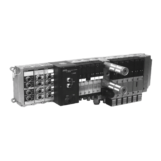
- Page 1 Valve terminal type 03/05 Electronics Manual Field bus connection FB16 Field bus protocols: FIPIO standard Telemecanique - APRIL 0506b Only valid in agreement with the printed documentation accompanying the product! Compare this edition code.
-
Page 2: Vifb16
VIFB16 - 03/05... - Page 3 D. Smith / Sturz Type setting: DUCOM / Sturz 0506b (Festo AG & Co., D-73726 Esslingen, 1997) The copying, distribution and utilization of this document as well as the communication of its contents to others without expressed authoriza- tion is prohibited. Offenders will be held liable for the payment of damages.
- Page 4 VIFB16 - 03/05 Order no.: 164222 Title: MANUAL Designation: P.BE-VIFB16-03/05-GB 0506b...
-
Page 5: Table Of Contents
VIFB16 - 03/05 Contents Contents ALLGEMEINE SICHERHEITSHINWEISE Bestimmungsgemäße Verwendung Zielgruppe WICHTIGE BENUTZERHINWEISE Gefahrenkategorien Piktogramme Hinweise zur vorliegenden Beschreibung XIII Service Chapter 1 SYSTEM SUMMARY SYSTEM SUMMARY System structure Type 03: Description of components Type 05: Description of components Description of the functions 1-11 Chapter 2 FITTING... - Page 6 VIFB16 - 03/05 Chapter 3 INSTALLATION GENERAL CONNECTION PRINCIPLES Cable selection – field bus cable Cable selection – operating voltages Connecting the cables to the plugs/sockets FIELD BUS NODE Opening and closing the node Configuring the valve terminal Setting the field bus address (connection point) 3-11 Setting "HOLD/STOP"...
- Page 7 TELEMECHANIQUE CONTROLERS/XTEL SOFTWARE 4-19 4.2.1 General notes on configuring for valve terminals 4-19 Field bus address (Connecting point) 4-19 FIPIO standard profile for Festo valve terminals 4-21 4.2.2 Installation under XTEL (from V52) 4-22 Versions of software required 4-22 Starting the configuration software...
- Page 8 APRIL/SOFTWARE ORPHEE CONTROLLERS 4-39 4.3.1 General information on configuring valve terminals 4-39 Field bus addresses 4-39 FIPIO standard profile for Festo valve terminals 4-41 4.3.2 Commissioning under ORPHEE (APRIL controllers) 4-42 Software version required 4-42 Selecting the controller and the...
- Page 9 VIFB16 - 03/05 Chapter 5 DIAGNOSIS AND ERROR TREATMENT SUMMARY OF DIAGNOSTIC POSSIBILITIES ON-THE-SPOT DIAGNOSIS LED displays Field bus node Valves Input/output modules TESTING THE VALVES STATUS BITS 5-11 Position of status bits 5-13 DIAGNOSIS VIA THE FIELD BUS (with XTEL) 5-14 General 5-14...
- Page 10 VIFB16 - 03/05 Appendix A TECHNICAL APPENDIX TECHNICAL SPECIFICATIONS CABLE LENGTH AND CROSS SECTION Calculating with graphs Calculating with a formula A-10 EXAMPLES OF CIRCUITRY A-12 Operating voltage connection type 03 A-12 Operating voltage connection type 05 A-13 4-input module PNP A-14 8-input module PNP A-15...
- Page 11 VIFB16 - 03/05 General safety instructions GENERAL SAFETY INSTRUCTIONS Designated use The valve terminals types 03/05 described in this manual are designated exclusively for use as follows: • for controlling pneumatic and electrical actuators (valves and output modules) • for interrogating electrical sensor signals by means of the input modules.
- Page 12 VIFB16 - 03/05 General safety instructions Target group This manual is directed exclusively at techni- cians who are trained in control and automat- ion technology and who have experience in installing, commissioning, programming and diagnosing programmable logic controllers (PLC) and field bus systems. 0506b...
- Page 13 VIFB16 - 03/05 General safety instructions IMPORTANT USER INSTRUCTIONS Danger categories This manual contains instructions on the hazards which may arise from improper or negligent use of the valve terminal. A distinction is made between the following instructions: WARNING This means that personal injury or damage to property may occur if these instructions are not observed.
- Page 14 VIFB16 - 03/05 General safety instructions Pictograms Pictograms and symbols supplement the danger instructions and draw attention to the consequences of dangers. The following pictograms are used: Uncontrolled movements of loose tubing. Unintentional movement of the connected actuators. High electric voltage or undefined switching states of the electronic components which affect the connected circuits.
- Page 15 VIFB16 - 03/05 General safety instructions Instructions on this manual This manual contains specific information on the installation, commissioning, programming and disgnosis of the valve terminals types 03/05 and the input/output modules. The following product-specific abbreviations are used in this manual: Abbreviation Meaning Terminal or...
-
Page 16: Service
General safety instructions PLEASE NOTE This Electronics Manual contains the user in- formation on the field bus node FB16 and on the input and output modules. All information on the pneumatic modules is to be found in the Pneumatics Manual P.BE-MIDI/MAXI-03-GB or P.BE-ISO-05-GB. -
Page 17: System Summary
VIFB16 - 03/05 1. User instructions 1. SYSTEM SUMMARY 0506b... - Page 18 VIFB16 - 03/05 1. User instructions Contents SYSTEM SUMMARY SYSTEM SUMMARY System structure Type 03: Description of components Type 05: Description of components Description of the functions 1-11 0506b...
-
Page 19: System Structure
1. User instructions 1.1 SYSTEM SUMMARY System structure Festo offers a solution to automation problems at machine level in the form of the valve terminal. Valve terminals of type 03/05 are constructed on a modular basis and permit combinations of... - Page 20 VIFB16 - 03/05 1. User instructions The valve terminal with fieldbus connection offers the following advantages: • can be fitted with digital I/Os and pneumatic valve locations • subsequent extension/conversion possible • small-scale valves • can be connected to various control systems •...
-
Page 21: Type 03: Description Of Components
VIFB16 - 03/05 1. User instructions Type 03: Description of components Valve terminal type 03 consists of individual modules. Each module is designed with different functions, connections, display and operating elements as shown below. Figure Meaning Node Electric modules (input/output modules), fitted with •... - Page 22 VIFB16 - 03/05 1. User instructions The following connection and display elements are to be found on the electric modules: other modules Meaning Output socket for electrical output Yellow LED (status display per output) Red LED (error display per output) Input socket for one electrical input Green LED (per input) Input socket for two electrical inputs...
- Page 23 VIFB16 - 03/05 1. User instructions The connections, display and operating elements shown below are to be found on the MIDI modules of type 03. Meaning Node with LEDs and field bus interface, detailed description see chapter "Installation" Yellow LEDs (status per valve solenoid) Manual override for valve coils (status per valve solenoid) Valve location inscription field (nameplate) Unused valve location with blanking plate...
- Page 24 VIFB16 - 03/05 1. User instructions The connections, display and operating elements shown below are to be found on the MAXI modules of type 03. Meaning Node with LEDs and field bus interface, detailed description see chapter "Installation" Yellow LEDs (per valve solenoid coil) Manual override (per valve solenoid coil) Valve location inscription field (signs) Unused valve location with blanking plate...
-
Page 25: Type 05: Description Of Components
VIFB16 - 03/05 1. User instructions Type 05: Description of components Valve terminal type 05 consists of individual modules. Each module is assigned with different functions, connections, display and operating elements. These are shown in the diagram below. Meaning Node Electronic modules (input/output modules), fitted with •... - Page 26 VIFB16 - 03/05 1. User instructions The connections, display and operating elements shown below are to be found on the ISO modules of type 05. Meaning Node with LEDs and field bus interface, detailed description see chapter "Installation" Fuse for inputs/sensors (pin 1) Adapter module Operating voltage connection of valve terminal type 05 Fuse for valves (pin 2)
-
Page 27: Description Of The Functions
VIFB16 - 03/05 1. User instructions Description of the functions Incoming field bus Continuing field bus Node Compressed air Work air Electric signal flow Fig. 1/11: Function summary of valve terminal type 03/05 The node takes control of the following functions: •... - Page 28 VIFB16 - 03/05 1. User instructions The input modules process the input signals (e.g. from sensors) and transmit these signals via the field bus to the bus controller. The output modules are universal electric outputs and control low-current consuming devices with posi- tive logic, e.g.
-
Page 29: Fitting
VIFB16 - 03/05 2. Fitting 2. FITTING 0506b... -
Page 30: Fitting The Components
VIFB16 - 03/05 2. Fitting Contents FITTING FITTING THE COMPONENTS Input/output modules End plates Hat rail clamping unit (type 03) TYPE 03: FITTING THE VALVE TERMINAL Wall fitting (type 03) Hat rail fitting (type 03) 2-10 TYPE 05: FITTING THE VALVE TERMINAL 2-12 Wall fitting (type 05) 2-12... - Page 31 VIFB16 - 03/05 2. Fitting 2.1 FITTING THE COMPONENTS WARNING Before fitting the components, switch off the following: • compressed air supply • power supply to the outputs (pin 2) • power supply to the electronic components (pin 1) You can thereby avoid: •...
-
Page 32: Input/Output Modules
VIFB16 - 03/05 2. Fitting PLEASE NOTE Treat all the modules and the components of the valve terminal with great care. Pay special attention to the following: • Screw connections must not be distorted or subjected to mechanical stress. • The screws must fit correctly (otherwise the threads will be damaged). - Page 33 VIFB16 - 03/05 2. Fitting Fitting (see also following diagram): PLEASE NOTE • Always place subsequently ordered modules behind the last module before the end plate. • Do not fit more than 12 electric modules. Fit the modules as follows: •...
-
Page 34: End Plates
VIFB16 - 03/05 2. Fitting End plates A left-hand and a right-hand end plate are required as a mechanical termination of the terminal. These end plates fulfil the following functions: • They comply with protection class IP65. • They contain connections/holes for the pro- tective earth cable. - Page 35 VIFB16 - 03/05 2. Fitting Earth the end plates as follows: • Right-hand end plate (type 03): In order to earth the right-hand end plate, connect the fitted cable on the inside to the appropriate contacts on the pneumatic modu- les or on the node (see diagram below).
-
Page 36: Hat Rail Clamping Unit (Type 03)
VIFB16 - 03/05 2. Fitting Hat rail clamping unit (type 03) The hat rail clamping unit is required if the terminal is to be fitted onto a hat rail (support rail as per EN 50022). The hat rail clamping unit is fastened to the back of the end plates as shown in the following diagram: Before fitting ensure that:... -
Page 37: Wall Fitting (Type 03)
VIFB16 - 03/05 2. Fitting 2.2 TYPE 03: FITTING THE VALVE TERMINAL Wall fitting (type 03) WARNING With long terminals use additional supporting brackets every 200 mm. This is to avoid the following: • overloading the fastening eyes on the left-hand end plate •... -
Page 38: Hat Rail Fitting (Type 03)
VIFB16 - 03/05 2. Fitting Hat rail fitting (type 03) The terminal is suitable for fitting onto a hat rail (support rail as per EN 50022). For this purpose there is a guide groove on the rear of all modules for hanging the terminal on the hat rail. CAUTION •... -
Page 39: Type 03
VIFB16 - 03/05 2. Fitting • Make sure that the fastening surface can carry this weight. • Fit a hat rail (support rail EN 50022 - 35x15; width 35 mm, height 15 mm). • Fasten the hat rail to the mounting surface at least every 100 mm. -
Page 40: Wall Fitting (Type 05)
VIFB16 - 03/05 2. Fitting 2.3 TYPE 05: FITTING THE VALVE TERMINAL Wall fitting (type 05) WARNING With long terminals (e.g. several I/O modules) use additional supporting brackets every 200 mm. This is to avoid the following: • overloading the fastening eyes on the left-hand end plate •... - Page 41 VIFB16 - 03/05 2. Fitting Fasten the terminal as follows: • Use 3 screws M10 on the adapter plate and the right-hand end plate (2) • 2 screws M6 on the left-hand end plate (1) If necessary use additional fitting possibilities as follows: •...
- Page 42 VIFB16 - 03/05 2. Fitting 2-14 0506b...
-
Page 43: Installation
VIFB16 - 03/05 3. Installation 3. INSTALLATION 0506b... -
Page 44: General Connection Principles
VIFB16 - 03/05 3. Installation Contents INSTALLATION GENERAL CONNECTION PRINCIPLES Cable selection – field bus cable Cable selection – operating voltages Connecting the cables to the plugs/sockets FIELD BUS NODE Opening and closing the node Configuring the valve terminal Setting the field bus address (connection point) 3-11 Setting "HOLD/STOP"... - Page 45 VIFB16 - 03/05 3. Installation 3.1 GENERAL CONNECTION PRINCIPLES WARNING Before installation or maintenance work is car- ried out, the following must be switched off: • the compressed air supply • power supply to the electronic components (pin 1) • power supply to the outputs/valves (pin 2) You thereby avoid: •...
-
Page 46: Cable Selection - Field Bus Cable
VIFB16 - 03/05 3. Installation Special advice on cable selection, bus cabling and on the allowable cable lengths is to be found in the following Schneider Automation (Telemechanique) manuals: • German edition: TSX DR FPW G (FIPWAY Zellennetzwerk/ FIPIO-Feldbus - Benutzerhandbuch) •... -
Page 47: Connecting The Cables To The Plugs/Sockets
Please refer to the following chapters for the pin assignment. When you have selected suitable cables, con- nect the Festo plug/sockets according to steps 1...7 below. 1. Open the plugs/sockets as follows (see diagram): •... - Page 48 VIFB16 - 03/05 3. Installation 2. Open the strain relief on the rear part of the housing. Pass the cable through as shown in the diagram below (PG = Conduit thread). Cable diameter: PG 7: 4.0 ... 6.0 mm PG 9: 6.0 ...
-
Page 49: Field Bus Node
VIFB16 - 03/05 3. Installation 3.2 FIELD BUS NODE Opening and closing the node WARNING Before installation or maintenance work is carried out, the following must be switched off: • compressed air supply • power supply to the electronic components (pin 1) •... - Page 50 VIFB16 - 03/05 3. Installation The following connection and display elements are to be found on the cover of the node: Green LED POWER I/O ERR Red LED Green LED Red LED Plug for field bus cable FUSE 2A 24VDC Power Fuse for supply...
-
Page 51: Configuring The Valve Terminal
VIFB16 - 03/05 3. Installation • Opening Unscrew the 6 Philips screws in the cover and carefully remove the cover by lifting upwards. Do not damage the cable through mechanical stress. • Closing Replace the cover. Place the cables for the operating voltage connection back into the housing so that they are not clamped. - Page 52 VIFB16 - 03/05 3. Installation Red LED Green LED Green LED Red LED Address selector switches Plug for field bus (connection cables point) Configuration selector Board 1 switches HOLD/STOP Shield Board 4 Board 2 Board 3 Plug for operating voltage connection Fig.
-
Page 53: Setting The Field Bus Address
VIFB16 - 03/05 3. Installation Setting the field bus address (connection point) The field bus address of the valve terminal should be set with the two address selector switches on board 3. The switches are numbe- red from 0...9. The arrow on the address selector switches indicates the field bus address set. - Page 54 VIFB16 - 03/05 3. Installation Example (Field bus address 4): UNITS Address selector switch UNIT figure Address selector switch TENS figure TENS Fig. 3/4: Function of the address selector switch Possible field bus addresses: Producer/ Address name Addresses Control system (PLC) (numbers) Schneider Automation Field bus...
-
Page 55: Setting "Hold/Stop
VIFB16 - 03/05 3. Installation Setting "HOLD/STOP" (error reaction of the outputs) The reaction of the outputs to an error (transmis- sion error on the FIPIO-field bus or interruption in the field bus cable) can be set as follows: DIL switch 1 Error reaction All outputs will be switched off if (STOP mode) -
Page 56: Type 03 Connecting The Operating Voltages
VIFB16 - 03/05 3. Installation 3.2.1 Type 03: Connecting the operating voltages WARNING • Use only PELV circuits as per IEC/DIN EN 60204-1 (Protective Extra-Low Voltage, PELV) for the electrical supply. Consider also the general requirements for PELV circuits in accordance with IEC/DIN EN 60204-1. - Page 57 VIFB16 - 03/05 3. Installation The 24 V operating voltages are connected at the lower left-hand edge of the node. POWER I/O ERR Operating voltage FUSE 2A 24VDC connection Fig. 3/7: Operating voltage connection The following + 24 V DC supplies are made via this connection: •...
- Page 58 VIFB16 - 03/05 3. Installation PLEASE NOTE Please note that with common voltage supply for pin 1 (electronic components and inputs) and pin 2 (outputs/valves), the lower tolerance of ± 10 % for both circuits must be observed. Check the 24 V operating voltage of the outputs while your system is operating.
- Page 59 VIFB16 - 03/05 3. Installation Calculating the current consumption type 03 The following table shows the calculation of the total current consumption for type 03 terminals. The values are rounded up. If you use other valves or modules, you should consult the appropriate technical specifications for their consumption.
- Page 60 VIFB16 - 03/05 3. Installation The following diagram shows the pin assign- ment of the operating voltage connection. 24 V supply 24 V supply for for electronic valves, outputs components and inputs (protective earth connection, leading contact) Fig. 3/9: Pin assignment of the operating voltage connection Protective earthing The valve terminal has two protective earth...
- Page 61 VIFB16 - 03/05 3. Installation Connection example (type 03) The following diagram shows the connection of a common 24 V supply for pins 1 and 2. Please note that: • the outputs/valves must be protected against short circuit/overload with an external 10 A fuse •...
- Page 62 VIFB16 - 03/05 3. Installation 3 1 2 4 Connecting cable for potential compensation of earth connections Fuse for inputs/sensors (2 A) 3.15 A 230 V 24 V External fuses DC 24V 10 A ± 10 % EMERGENCY STOP Earth cable connection pin 4 designed for 12 A Fig.
-
Page 63: Type 05 Connecting The Operating Voltages
VIFB16 - 03/05 3. Installation 3.2.2 Type 05: Connecting the operating voltages WARNING • Use only PELV circuits as per IEC/DIN EN 60204-1 (Protective Extra-Low Voltage, PELV) for the electrical supply. Consider also the general requirements for PELV circuits in accordance with IEC/DIN EN 60204-1. - Page 64 VIFB16 - 03/05 3. Installation The 24 V operating voltages are connected at the adapter plate between the node and the valves. The operating voltage connection for the node and the I/O modules is supplied via the adapter cable. Operating voltage connection type 05 Fuse for valves (4 A slow blowing) Adapter cable...
- Page 65 VIFB16 - 03/05 3. Installation PLEASE NOTE Please note that with common voltage supply for pin 1 (electronic components and inputs) and pin 2 (outputs/valves), the lower tolerance of 10 % for both circuits must be observed. Check the 24 V operating voltage of the outputs while your system is operating.
- Page 66 VIFB16 - 03/05 3. Installation Calculating the current consumption type 05 The following table shows the calculation of the total current consumption for the ISO terminal type 05. The values are rounded up. If you use other valves or modules, you should consult the appropriate technical specifications for their con- sumption.
- Page 67 VIFB16 - 03/05 3. Installation The following diagram shows the pin assignment of the operating voltage connection on the adapter plate. 24 V supply 24 V supply for for electronic valves, outputs components and inputs (protective earth connection, leading contact) Fig.
- Page 68 VIFB16 - 03/05 3. Installation Connection example (type 05) The following diagram shows the connection of a common 24 V supply for pins 1 and 2. Please note that: • the outputs/valves must be protected against short circuit/overload with an external 10 A fuse (slow blowing) •...
- Page 69 VIFB16 - 03/05 3. Installation Operating voltage connection Fuse for valves (4 A) Connected adapter cable Connecting cable for potential compensation of 3 1 2 4 earth connections 3.15 A 24 V 230 V External fuses DC 24 V 10 A EMERGENCY ±...
-
Page 70: Connecting The Field Bus
VIFB16 - 03/05 3. Installation 3.2.3 Connecting the field bus Recommendation: For connecting the FIPIO field bus use suitable connector fittings, e.g. from Schnei- der Automation (Telemecanique): • Main cable (Trunk cable) TSX FP CA xxx • Tap cable (Drop cable) TSX FP CC xxx •... - Page 71 VIFB16 - 03/05 3. Installation Variation of connection for branch lead Serial connection ACC4 FIPIO incoming FIPIO outgoing Festo- Field bus connecter with PG 9 or PG 13,5 FIPIO incoming close with FIPIO outgoing protective cap (IP65) Festo- Field bus...
- Page 72 VIFB16 - 03/05 3. Installation CAUTION • Please observe the polarity when connecting the field bus interface. • Also connect the screen braid to Pin 4 The following diagram shows the pin assign- ment of the field bus interface. Connect the field bus cables to the appropriate pins of the bus cable socket.
-
Page 73: Connection Instructions Fipio/Telemecanique
VIFB16 - 03/05 3. Installation Connection instructions FIPIO/Telemecanique PLEASE NOTE Always check the pin assignment of the module in the PLC manual for your controller. Valve Connection per branch cable Example TAP ACC4 terminal - Pin (Drop cable) assignment ACC4 valve terminal D1+ / D2+... - Page 74 (IP65). • The drop cable can be connected to the Festo field bus sockets with PG9 or 13.5. • The connection by branch cable has the disadvantage that an ACC4 connecting sock- et must always be used. With serial connec- tion of the valve terminal the ACC4 is not required.
-
Page 75: Cable Termination/Bus Termination
VIFB16 - 03/05 3. Installation Cable termination/bus termination PLEASE NOTE Attach a terminating resistor to each end of a cable or bus segment. The following connection is possible in respect of a valve terminal: Connection per branch cable Serial connection Terminating resistor cannot be ACC7 attached. -
Page 76: Connecting The Input Modules
VIFB16 - 03/05 3. Installation 3.3 CONNECTING THE INPUT MODULES WARNING Before installation or maintenance work is car- ried out, the following must be switched off: • the compressed air supply • the power supply to the electronic components (pin 1). •... - Page 77 Green INPUT input INPUT digital LED per inputs digital input Fig. 3/19: Digital PNP input modules (4/8 inputs) Recommendation for 8-input modules: Use the Festo duo-cable to connect two sensors via one plug at low cost. 3-35 0506b...
-
Page 78: Pin Assignment
VIFB16 - 03/05 3. Installation Pin assignment The following diagram shows the pin assign- ment of all the PNP/NPN inputs. Pin assignment Pin assignment 4 inputs 8 inputs n. c. Input Ix+1 Input Input + 24 V + 24 V n. -
Page 79: Connecting The Output Modules
VIFB16 - 03/05 3. Installation 3.4 CONNECTING THE OUTPUT MODULES WARNING Before installation or maintenance work is car- ried out, the following must be switched off: • the compressed air supply • the power supply to the electronic components (pin 1). •... - Page 80 VIFB16 - 03/05 3. Installation Four transistor outputs are available for the user on the output modules of the valve terminal. The outputs have positive logic (PNP outputs). Output module (4 outputs) Yellow LED per output Red LED per output Socket with one OUTPUT...
- Page 81 VIFB16 - 03/05 3. Installation Pin assignment The following diagram shows the pin assign- ment of all outputs. Pin assignment 4 inputs n. c. Output n. c. n. c. Output n. c. Ox+1 n. c. Output n. c. Ox+2 n. c. Output Ox+3 n.
- Page 82 VIFB16 - 03/05 3. Installation 3-40 0506b...
-
Page 83: Chapter 4 Commissioning
VIFB16 - 03/05 4. Commissioning 4. COMMISSIONING 0506b... - Page 84 VIFB16 - 03/05 4. Commissioning Contents COMMISSIONING BASIC PRINCIPLES OF CONFIGURATION AND ADDRESSING 4-5 General Switching on the operating voltage Calculating the configuration data Calculating the number of inputs/outputs type 03 Calculating the number of inputs/outputs type 05 Address assignment of the valve terminal 4-12 General (types 03 and 05)
- Page 85 TELEMECHANIQUE CONTROLERS/ XTEL SOFTWARE 4-19 4.2.1 General notes on configuring for valve terminals 4-19 Field bus address (Connecting point) 4-19 FIPIO standard profile for Festo valve terminals 4-21 4.2.2 Installation under XTEL (from V52) 4-22 Versions of software required 4-22...
- Page 86 4. Commissioning APRIL/SOFTWARE ORPHEE CONTROLLERS 4-39 4.3.1 General information on configuring valve terminals 4-39 Field bus addresses 4-39 FIPIO standard profile for Festo valve terminals 4-41 4.3.2 Commissioning under ORPHEE (APRIL controllers) 4-42 Software version required 4-42 Selecting the controller and...
-
Page 87: Commissioning
VIFB16 - 03/05 4. Commissioning 4.1 BASIC PRINCIPLES OF CONFIGURATION AND ADDRESSING General The valve terminal must be configured very accurately, since different configuration specifications may be necessary for each termi- nal due to the modular structure. Observe here also the specifications in the following sections. 0506b... -
Page 88: Switching On The Operating Voltage
VIFB16 - 03/05 4. Commissioning Switching on the operating voltage When the control system is switched on, the controller compares the nominal and the actual configuration. For the configuration run it is important that: • the specifications on configuration are as complete as possible and are correct;... -
Page 89: Calculating The Configuration Data
VIFB16 - 03/05 4. Commissioning Calculating the configuration data Before configuring, calculate the exact number of available inputs/outputs. A modular valve termi- nal consists of a varying number of I/Os, depending on the type ordered. PLEASE NOTE • The terminal provides four status bits for diagnosis. -
Page 90: Calculating The Number Of Inputs/Outputs Type
VIFB16 - 03/05 4. Commissioning Calculating the number of inputs/outputs type 03 Copy the table for further calculations on the number of inputs and outputs. Table for calculating the inputs/outputs of type 03 INPUTS Σ ⋅ 1. Number of 4-input modules ______ Σ... -
Page 91: Calculating The Number Of Inputs/Outputs Type
VIFB16 - 03/05 4. Commissioning Calculating the number of inputs/outputs type 05 Copy the table for further calculations. Please observe that the calculation of outputs differs for type 03 and type 05. Table for calculating the number of inputs/outputs of type 05 INPUTS ⋅... -
Page 92: General (Types 03 And 05)
VIFB16 - 03/05 4. Commissioning Address assignment of the valve terminal General (types 03 and 05) The address assignment of the outputs of a modular valve terminal depends on the number of valve locations fitted on the terminal. A distinction must be made between the following fitting variants: •... -
Page 93: Basic Rule 1
VIFB16 - 03/05 4. Commissioning Basic rule 1 With a mixed fitting, consideration is given to the address assignment of the valves, digital I/O modules and status bits. Outputs: The address assignment of the outputs does not depend on the inputs. 1.1 Address assignment of valves: •... - Page 94 VIFB16 - 03/05 4. Commissioning Inputs: The address assignment of the inputs does not depend on the outputs. 2.1 Address assignment of the input modules: • Addresses should be assigned in ascending order without gaps. • Counting should begin on the node from right to left.
- Page 95 VIFB16 - 03/05 4. Commissioning The diagram below shows the address assign- ment with mixed fitting. Fig. 4/4: Address assignment of a valve terminal with digital I/Os Remarks on the diagram • If single solenoid valves are fitted onto D-type sub-base modules, four addresses will be as- signed for solenoid valve coils;...
-
Page 96: Basic Rule 2
VIFB16 - 03/05 4. Commissioning Basic rule 2 If only valves are used, the address assignment is always as described in basic rule 1. PLEASE NOTE • Maximum 26 solenoid valve coils can be addressed. • There is no rounding up of the last two positions on the valve side. -
Page 97: Address Assignment After Extension Conversion
VIFB16 - 03/05 4. Commissioning Address assignment after extension/ conversion A special feature of the modular valve terminal is its flexibility. If the demands placed on the machine change, then the number of valves fitted on the terminal can also be modified. CAUTION If extensions or conversions are made to the terminal at a later stage, this may result in a... - Page 98 VIFB16 - 03/05 4. Commissioning The diagram below shows the modifications to the address assignment in the example of an extension to the standard fitting shown in the previous diagram. Fig 4/5: Address assignment of a valve terminal after extension/ conversion Remark: Air supply modules and intermediate air supply...
-
Page 101: General Notes On Configuring For Valve Terminals
VIFB16 - 03/05 4. Commissioning 4.2 TELEMECHANIQUE CONTROLLERS/XTEL SOFTWARE 4.2.1 General notes on configuring for valve terminals Field bus address (Connecting point) A valve terminal is identified on the FIPIO bus by its field bus address. The field bus address number represents the physical address of the device on the FIPIO bus. - Page 102 VIFB16 - 03/05 4. Commissioning PLEASE NOTE • Before commissioning, ensure that the valve terminal has been set to an allowable field bus address (see Chapter 3.2). • A change in the address only becomes effective after switching off/on the power supply to the valve terminal.
-
Page 103: Fipio Standard Profile For Festo Valve Terminals
FIPIO bus through a clearly defined device reference. PLEASE NOTE Configure a Festo valve terminal with FB16 as follows: • as STD_P device family • as basic device (standard profile) FSD_C8 Here: •... -
Page 104: Installation Under Xtel (From V52)
4. Commissioning 4.2.2 Installation under XTEL (from V52) Versions of software required The configuration, programming and diagnosis of Festo valve terminals with FB16 is possible with the following versions using the XTEL-CONF software package: • XTEL V52, if the diskette “Catalog TXT R CTG V52”... -
Page 105: Starting The Configuration Software
VIFB16 - 03/05 4. Commissioning Starting the configuration software The following basic steps are required to configure a Festo valve terminal: • Start the configuration software “CONF” in the “Station tools” window. On being called up, the configuration software displays the following screen: Fig.4/8: XTEL-CONF Tools Introductory Screen... -
Page 106: Entering The Valve Terminal
VIFB16 - 03/05 4. Commissioning Selecting the controller and the processor Before configuring a valve terminal, you must first select and enter a processor with integrated FIPIO interface. To do this, proceed as follows: • From the “Configure” menu select “Configure - Rack I/O”. - Page 107 VIFB16 - 03/05 4. Commissioning Fig. 4/9: Field bus configuration screen Remarks: The screen is divided into 64 fields (0 to 63 ). Each field represents a field bus address on the FIPIO bus and can be occupied by a field bus slave (with the exception of fields 0 and 63, which are reserved for the controller or the programming terminal).
-
Page 108: Device Family
VIFB16 - 03/05 4. Commissioning When you have correctly selected the field bus address, • press the ENTER key or • double click on the line shown in grey. This will open the screen for the selection of the device family. Allocation to the STD_P device family In the screen for selecting the device family, the valve terminal must be allocated to the STD_P... -
Page 109: Configuring The Valve Terminal As Base Device Fsd C8
VIFB16 - 03/05 4. Commissioning Configuring the valve terminal as base device FSD C8 Under “Base” select the defined device reference FSD C8 for the valve terminal. Fig. 4/10: “STD_P device configuration” screen 4-27 0506b... -
Page 110: Defining The Parameters Of The Valve Terminal
VIFB16 - 03/05 4. Commissioning The other menu items mean: • Connection point: Data field which cannot be changed, conta- ining the FIPIO address of the valve terminal (between 1 and 62). • Device Communication module: This field (in grey) is not used by the valve terminal. - Page 111 VIFB16 - 03/05 4. Commissioning PLEASE NOTE • For Festo valve terminals only the task priority needs to be specified. • Valve terminals are base devices with the standard profile FSD_C8 and require no other parameters to be set. •...
- Page 112 VIFB16 - 03/05 4. Commissioning Fig. 4/11: Task priority setting screen (Parameters) The other menu options are: • Connection point: Data field which cannot be changed, conta- ining the FIPIO address of the valve terminal (between 1 and 62). • Base: This data field, which cannot be changed, holds the device reference and description for...
-
Page 113: Programming Under Xtel (V52)
VIFB16 - 03/05 4. Commissioning 4.2.3 Programming under Xtel (V52) Available objects With the various objects which are directly accessible in the control program, the user has access to the inputs of the valve terminals and sets the outputs of the valve terminals. Access to these objects is only possible if re-configuration is first carried out with the software tool PL7-3. - Page 114 VIFB16 - 03/05 4. Commissioning The following table explains the mnenomic codes for the objects available to the application. For Festo valve terminals only the objects for device reference FSD_C8 are given. Object Description Access Format 8 words which are the image of the...
-
Page 115: Addressing The Inputs
VIFB16 - 03/05 4. Commissioning Addressing the inputs Access to the inputs of valve terminals is through the RIW objects. These objects are read in cyclically at the start of a program. Addressing is bit-wise or word-wise in accordance with the following rule: For a bit access: RIWx,0,y, t... -
Page 116: Addressing The Outputs
VIFB16 - 03/05 4. Commissioning Addressing the outputs Access to the outputs of valve terminals is through the ROW objects. These objects are output cyclically at the end of a program. Addressing is bit-wise or word-wise in accord- ance with the following rule: For a bit access: ROWx,0,y,t position of the bit in the word:... -
Page 117: Addressing Examples
VIFB16 - 03/05 4. Commissioning Addressing examples Example 1 - Inputs Addressing the inputs (sequential numbering at the valve terminal). Concrete allocation see Example 3. Bit number in the object (hexadecimal) Object RIW x,0,0 15 14 13 12 11 10 9 Object RIW x,0,1 31 30 29 28 27 26 25 24 23 22 21 20 19 18 17 16 Object RIW x,0,2... - Page 118 VIFB16 - 03/05 4. Commissioning Example 2 - Outputs Addressing the outputs (sequential numbering at the valve terminal). Concrete allocation see Example 3. Bit number in the object (hexadecimal) Object ROW x,0,0 15 14 13 12 11 10 9 Object ROW x,0,1 31 30 29 28 27 26 25 24 23 22 21 20 19 18 17 16 Object ROW x,0,2 47 46 45 44 43 42 41 40 39 38 37 36 35 34 33 32...
- Page 119 VIFB16 - 03/05 4. Commissioning The following figure shows a specific example of valve terminal addressing in standard occupancy from Chapter 4.1: I/O modules Sub base Fig. 4/15 : XTEL example - valve terminal addressing with field bus address 7 4-37 0506b...
- Page 120 VIFB16 - 03/05 4. Commissioning Shutdown behaviour of outputs (HOLD/STOP) In normal operation the valve terminal outputs behave in accordance with the commands from the PLC program. At the end of each operating cycle they will be set/reset in accordance with the values sent by the application program.
-
Page 121: April/Software Orphee Controllers
VIFB16 - 03/05 4. Commissioning 4.3 APRIL/SOFTWARE ORPHEE CONTROLLERS 4.3.1 General information on configuring valve terminals Field bus address A valve terminal is identified on the FIPIO-bus by means of its field bus address. The number of the field bus address represents the physical address of the device on the FIPIO-bus. - Page 122 VIFB16 - 03/05 4. Commissioning PLEASE NOTE • Before commissioning, make sure that a permitted field bus address is set on the valve terminal (see chapter 3.2). • Modification of the address does not become effective until the operating voltage of the valve terminal is switched off and then on again.
-
Page 123: Valve Terminals
VIFB16 - 03/05 4. Commissioning FIPIO standard profile for Festo valve terminals Festo valve terminals belong to the device family STD_P. This device family includes the FIPIO standard profiles which permit external field bus slaves to be connected to the FIPIO-bus by means of a clearly defined device reference. -
Page 124: Commissioning Under
The configuration editor of ORPHEE permits the configuration and commissioning of the field bus slaves on the FIPIO-bus. Configuration of the Festo valve terminals with FB16 requires a version of ORPHEE ≥ V6.2. The following sections describe the procedure which permits the use of Festo valve terminals on the APRIL-5000 controlled FIPIO-bus. -
Page 125: Entering The Valve Terminal
VIFB16 - 03/05 4. Commissioning Entering the valve terminal Valve terminals can be accessed in the STD_P family of the configuration screen of the FIPIO- bus. Always proceed as follows: • Activate the function "EQT STD" in the menu PLC CONFIGURATION (FIPIO NETWORK) in order to enter a valve terminal as device family STD_P on the FIPIO. -
Page 126: Configuring Valve Terminals
VIFB16 - 03/05 4. Commissioning Configuring valve terminals The valve terminal entered then appears as Device reference FSD_C8 in the list of connec- ted field bus slaves. In order to undertake more entries (e.g. parameter entries), proceed as follows: • Use the arrow keys to select the valve termi- nal in the list. - Page 127 Comment: Comment entry line. This text is later visible e.g. in the dynamic display. Here you can enter, in particular, the device names (e.g. Festo valve terminal) belonging to the device reference. • Input tabulation - Fault: Error word of the input tables. This shows whether the inputs formed under "Input...
- Page 128 VIFB16 - 03/05 4. Commissioning • Input tabulation - Words: Table of 8 words of type %MW, in which the states of the inputs of the valve terminal are cyclically transmitted and entered. The up-to- date information in the various %MW can be found in the chapter "Image of the inputs of the valve terminal.”...
-
Page 129: Programming Under Orphee
Declaration Editor. Make sure that you carry out this assignment without mistakes. You will then avoid addressing errors. Fig. 4/ 19: Objects available for Festo valve terminals All the error messages of the valve terminal can trigger diagnostic processing %TD (like each card in the rack and every other device connected to the FIPIO-bus). -
Page 130: Image Of The Inputs Of A Valve Terminal
VIFB16 - 03/05 4. Commissioning Image of the inputs of a valve terminal Access to the inputs of the valve terminal takes place with 8 %MW words in the input table defined in the configuration editor. This table is read cyclically at the start of the control cycle (before the user program is executed) and updated. - Page 131 VIFB16 - 03/05 4. Commissioning After the addressing of the outputs, you will find a concrete addressing example of the inputs and outputs of a valve terminal. PLEASE NOTE The contents of this input table are only valid when the error word of the input tables (Input tabulation - Fault) is 0.
-
Page 132: Image Of The Outputs Of The Valve Terminal
VIFB16 - 03/05 4. Commissioning Image of the outputs of the valve terminal Access to the outputs of the valve terminal takes place with 8 %MW words in the output table defined in the configuration editor. This table is read cyclically at the start of the control cycle (before the user program is executed) and updated. -
Page 133: Valve Terminal
VIFB16 - 03/05 4. Commissioning Addressing example The following illustrations show as an example the concrete addressing of the valve terminal fitted in the standard manner from chapter 4.1. The following assumptions have been made: I/O tables, fixed in the configuration editor: •... - Page 134 VIFB16 - 03/05 4. Commissioning Addresses of Assignment of the input table of a valve terminal the table %MW n (0..7) %MW 1210 %MW 1211 %MW 1212 %MW 1213 %MW 1214 Reserved (not used by the valve terminal) %MW 1215 %MW 1216 %MW 1217 Digital inputs: fields 0 ...
- Page 135 VIFB16 - 03/05 4. Commissioning 10 12 Addressing output 5 (Bit 5 in MW1200): %MW1200:X5 Addressing input 8 (Bit 8 in MW1210): %MW1210:X8 Fig. 4/24: Example 3 – ORPHEE addressing of a valve terminal with %MW1200 and %1210 4-53 0506b...
-
Page 136: Error Word Of The Input Table
VIFB16 - 03/05 4. Commissioning Error word of the input table The error word of the input table can be specified in the input mask for the FIPIO configuration of the valve terminal "Parametering standard equipement FSD C8.” This error word informs the control program whether or not the current input image is valid or not. -
Page 137: Shutdown Behaviour Of Outputs
VIFB16 - 03/05 4. Commissioning Shutdown behaviour of outputs (HOLD/STOP) The outputs of the valve terminal react in normal operation according to the PLC program. The output words are transferred to the valve terminal via the field bus at the end of each program cycle. - Page 138 VIFB16 - 03/05 4. Commissioning 4-56 0506b...
-
Page 139: Chapter 5 Diagnosis And Error Treatment
VIFB16 - 03/05 5. Diagnosis/error treatement 5. DIAGNOSIS AND ERROR TREATMENT 0506b... - Page 140 VIFB16 - 03/05 5. Diagnosis/error treatement Contents DIAGNOSIS AND ERROR TREATMENT SUMMARY OF DIAGNOSTIC POSSIBILITIES ON-THE-SPOT DIAGNOSIS LED displays Field bus node Valves Input/output modules TESTING THE VALVES Starting the test routine 5-10 Stopping the test routine 5-10 STATUS BITS 5-11 Position of status bits 5-13...
-
Page 141: Summary Of Diagnostic Possibilities
The modular valve terminal offers extensive and user-friendly possibilities of diagnosis and error treatment. Depending on the equipment fitted, the following possibilities are available: Equipment on the valve terminal Input modules FB16 (electrical inputs) Dia- Status bits LEDs Diagnostic word... -
Page 142: On-The-Spot Diagnosis
VIFB16 - 03/05 5. Diagnosis/error treatment 5.2 ON-THE-SPOT DIAGNOSIS LED displays Field bus node The LEDs on the cover of the node indicate the operating status of the valve terminal. Green LED (operating POWER I/O ERR status display) Red LED (error display) Fig. - Page 143 VIFB16 - 03/05 5. Diagnosis/error treatment NET (green) No communication through the field Check... bus. Possible causes: • no PS program active • switched off or faulty device field • field bus circuit bus circuit • interrupted, short-circuited or • field bus connection damaged field bus connection flashing Communication normal on the field...
-
Page 144: Valves
VIFB16 - 03/05 5. Diagnosis/error treatment Valves There is a yellow LED for each valve solenoid coil on the valve bridges. This LED shows the switching status of the valve solenoid coil. yellow LEDs Switching position of Meaning valve solenoid coil Yellow out Basic position Logic 0 (no signal) - Page 145 VIFB16 - 03/05 5. Diagnosis/error treatment There is a yellow LED for each valve solenoid coil on the ISO valve terminal. This LED shows the switching status of the valve solenoid coil. 12 14 12 14 12 14 yellow LEDs Switching position of Meaning valve solenoid coil...
-
Page 146: Input/Output Modules
VIFB16 - 03/05 5. Diagnosis/error treatment Input/output modules There are one or two LEDs (status displays) next to the relevant connections on the in- put/output modules. The colours of these LEDs are: • green (status display of digital inputs) • yellow (status display of digital outputs) •... -
Page 147: Testing The Valves
VIFB16 - 03/05 5. Diagnosis/error treatment 5.3 TESTING THE VALVES WARNING Switch off the compressed air supply before testing the valves. You thereby avoid undesired or dangerous movement of the actuators. CAUTION • This test function runs automatically within the terminal. All valves are switched on and off cyclically. -
Page 148: Starting The Test Routine
VIFB16 - 03/05 5. Diagnosis/error treatment Starting the test routine 1. Switch off the power supplies (pins 1 and 2). 2. Open the node. 3. Note the positions of the address selector switch and the DIL switch elements. 4. Set DIL switch elements to OFF. 5. -
Page 149: Status Bits
VIFB16 - 03/05 5. Diagnosis/error treatment 5.4 STATUS BITS Irrespective of the station diagnosis set, the valve terminal provides 4 status bits for diagno- sis. PLEASE NOTE : The status bits of the valve terminal are only available if the terminal is fitted with input modules. - Page 150 VIFB16 - 03/05 5. Diagnosis/error treatment The diagnostics information of the four status bits is coded and has the following meaning: Diagnostic Meaning Cause information Monitors the tolerance of the Operating voltage at pin 2 of valves operating voltage of the valves operating voltage connection and electrical outputs.
-
Page 151: Position Of Status Bits
VIFB16 - 03/05 5. Diagnosis/error treatment Position of status bits The status bits occupy four addresses in the address range of the inputs. The position of the status bits follows those of the inputs. Inputs Addresses of status RIW word number Example for field bits (0...63) bus address 7 *... -
Page 152: Diagnosis Via The Field Bus (With Xtel)
VIFB16 - 03/05 5. Diagnosis/error treatment 5.5 DIAGNOSIS VIA THE FIELD BUS (with XTEL) General The diagnostic information of a valve terminal is grouped together in diagnostic words. With these diagnostic words, the following error states are communicated to the control system. -
Page 153: System Bits And System Words
VIFB16 - 03/05 5. Diagnosis/error treatment System bits and system words The diagnostic information in the following table applies to all FIPIO field bus slaves. They are described in detail in your device manual. The valve terminal affects these system bits and words like any other slave. -
Page 154: Statusa Module Diagnosis
VIFB16 - 03/05 5. Diagnosis/error treatment STATUSA Module diagnosis This 16 bit word contains diagnostic data for the valve terminal and diagnostic data for communication with valve terminals through the FIPIO bus. STATUSAx,0,0 always 0 for valve terminals field bus address in the FIPIO bus (1 to 62 in decimal format) Standard FIPIO status register... - Page 155 VIFB16 - 03/05 5. Diagnosis/error treatment Definition of the STATUSA registers Description Valve terminal diagnosis (8 low order bits) Short circuit/overload *) Internal module fault (breakdown) Hardware configuration error Error in communication with the PLC Reserved Status derived from the PLC (8 high order bits) Configuration error Module missing Module out of operation...
-
Page 156: Validity Of The Inputs ("Rd" Register)
VIFB16 - 03/05 5. Diagnosis/error treatment Validity of the inputs (”RD” register) This 16 bit word shows faults which arise on updating the RIW images of the inputs to the valve terminal. The high byte of RD is produ- ced by the valve terminal, the low byte by the PLC. -
Page 157: Xtel Diagnosis Tools (Setting Tools)
VIFB16 - 03/05 5. Diagnosis/error treatment XTEL Diagnosis tools (Setting tools) The SYSDIAG and ADJUST tools from the software centre XTEL serve for the diagnosis and adjustment of valve terminals as well as for other devices of the STD_P family. It will be set just as accurately as any other device in the STD_P family. -
Page 158: Diagnose Via
VIFB16 - 03/05 5. Diagnosis/error treatment 5.6 DIAGNOSE VIA FIELD BUS (ORPHEE) System diagnosis The functions of the system diagnosis for the valve terminal connected to the FIPIO-bus are shown in the dynamic display. It is possible: • to read the hardware configuration and to compare it with the programmed configuration in the controller;... - Page 159 VIFB16 - 03/05 5. Diagnosis/error treatment The current configuration of the valve terminal and its error status are shown and evaluated as follows: Fig. 5/14a: Device-specific analysis of a valve terminal (example EF3) 5-21 0506b...
-
Page 160: Short Circuit/Overload At
VIFB16 - 03/05 5. Diagnosis/error treatment The possible errors are grouped into the follo- wing three categories in the ORPHEE software: Error General meaning Valve terminal diagnosis category Internal Internal errors concern the Not relevant errors general function of a hardware module or the FIPIO slave. - Page 161 VIFB16 - 03/05 5. Diagnosis/error treatment With external errors, it is possible to trigger diagnostic processing via %TD, providing this was agreed when the valve terminal was defined in the configuration editor (see diagram below). Fig. 5/15: Defining the diagnostic processing %TD for a field bus slave As soon as an error is registered on the FIPIO-bus, e.g.
-
Page 162: Evaluating The Error Word Of The Input Table
VIFB16 - 03/05 5. Diagnosis/error treatment Evaluating the error word of the input table The error word of the input table can be specified in the input mask for the FIPIO configuration of a valve terminal "Parametering a standard equipment FSD C8.” This error word informs the control program whether the current input image is valid or not. - Page 163 VIFB16 - 03/05 5. Diagnosis/error treatment This error word ("Validity of the inputs”) assumes the hexadecimal value FF as soon as: • a valve terminal is separated from the FIPIO-bus or • the power supply to the electrical inputs sen) is below the tolerance (e.g. internal fuse triggered) or •...
-
Page 164: Error Treatment
VIFB16 - 03/05 5. Diagnosis/error treatment 5.7 ERROR TREATMENT Short circuit/overload at an output module In the case of short circuit or overload: • the digital output will be switched off, • the red LED of the relevant output will light up, •... - Page 165 VIFB16 - 03/05 Appendix A TECHNICAL APPENDIX 0506b...
- Page 166 VIFB16 - 03/05 Appendix A Contents TECHNICAL APPENDIX TECHNICAL SPECIFICATIONS General Operating voltage of electronic components and inputs Operating voltage of outputs/valves Electronic input modules Electronic output modules Field bus Electromagnetic compatibility (EMC) CABLE LENGTH AND CROSS SECTION Calculating with graphs Calculating with a formula A-10 EXAMPLES OF CIRCUITRY...
-
Page 167: Technical Specifications
(as per DIN 40050) Temperature during • operation C . . . +50 • storage/transport C . . . +60 Chem. resistance see Festo-Pneumatic catalog (resistance table) Vibrations (as per DIN/IEC 68 part 2-6 and IEC 721/ part 2-3) • transport 3.5 mm distance... -
Page 168: Operating Voltage Of Electronic Components And Inputs
VIFB16 - 03/05 Appendix A Operating voltage of electronic components and inputs (Pin 1 – operating voltage connection) • Rated value DC 24 V (protected against incorrect polarity) • Tolerance ± 25 % (DC 18 V . . . 30 V) •... -
Page 169: Electronic Input Modules
VIFB16 - 03/05 Appendix A Electronic input modules (PNP/NPN) Input voltage range DC 0 ... 30 V Logic level PNP • ON ≥ 12.5 V • OFF ≤ 7 V Logic level NPN • ON ≤ 5 V • OFF ≥... -
Page 170: Field Bus
VIFB16 - 03/05 Appendix A Field bus Design FIPIO standard Transmission type serial asynchronous Protocol FIPIO Configuration • Device family • STD_P • Basic device • FSD_C8 (standard profile) Baud rate 1 Mbaud • max. 1 km without repeater Cable length •... -
Page 171: Cable Length And Cross Section
VIFB16 - 03/05 Appendix A CABLE LENGTH AND CROSS SECTION PLEASE NOTE The following information is for the exclusive use of personnel trained in electrotechnology and who are already familiar with the contents of the chapters on "Installation" in this manual. A load-dependent drop in voltage occurs on all three cables for the operating voltage supply to a valve terminal. -
Page 172: Calculating With Graphs
VIFB16 - 03/05 Appendix A Calculating with graphs Proceed as follows: 1. Calculate the maximum current consumption of the outputs/valves (I 2. Calculate the lowest voltage to be expected on the power unit during operation (V Omin Take into consideration: •... - Page 173 VIFB16 - 03/05 Appendix A in volt Omin Current I in ampere +10% 26,4 Cross section 1.5 mm -10% 21,6 (16 AWG) Cable length in metres in volt Omin Current I in ampere +10% 26,4 Cross section 2.5 mm -10% 21,6 (14 AWG) Cable length in metres...
-
Page 174: Calculating With A Formula
VIFB16 - 03/05 Appendix A Calculating with a formula Proceed as follows: 1. Calculate the maximum current consumption of the inputs and electronic components (I as well as of the outputs/valves (I 2. Calculate the lowest voltage to be expected on the power unit during operation (V Omin Take into consideration:... - Page 175 VIFB16 - 03/05 Appendix A Formula for calculating cable lengths: κ − V ) ⋅ A ⋅ Omin TERMINAL min L ≤ 2 ⋅ I This means: • = 24 V ± 10%, 21.6 V: V TERMINAL ≥ 21.6 V minimal: V TERMINALmin •...
-
Page 176: Examples Of Circuitry
VIFB16 - 03/05 Appendix A EXAMPLES OF CIRCUITRY Operating voltage connection type 03 1: 24 V supply 2: 24 V supply assignment to electronic Outputs/valves (node) components 3: 0 V 4: PE Valves Circuitry (must be fused externally) Electrical outputs examples and internal structure... -
Page 177: Operating Voltage Connection Type 05
VIFB16 - 03/05 Appendix A Operating voltage connection type 05 1: 24 V supply 2: 24 V supply to assignment to electronic outputs/valves (adapter components plate) and inputs 4: PE 3: 0 V Circuitry Electrical examples outputs (must be and internal fused externally) structure Adapter cable... -
Page 178: 4-Input Module Pnp
VIFB16 - 03/05 Appendix A 4-input module PNP Internal structure 24 V ± 25 % n.c. PLC/I-PC Logic recognition (via field bus) Green LED I 2: n.c. 3: 0 V assignment 1: + 24 V 4: Input I Examples of circuitry positive positive... -
Page 179: 8-Input Module Pnp
Green LED I 3: 0 V 2: Input I assignment 1: + 24 V 4: Input I Examples of 2-fold distributor circuitry (T-adapter, e.g. Festo duo cable) Sensor 2 (I Sensor 1 (I Fig. A/6: Circuitry example: 8-input module PNP A-15 0506b... -
Page 180: 4-Input Module Npn
VIFB16 - 03/05 Appendix A 4-input module NPN Internal structure n.c. PLC/I-PC Logic identifi- cation I green LED Ix 24 V ± 25 % 2: n.c. 3: 0 V assignment 4: Input I 1: + 24 V Circuitry examples negative negative switching switching... -
Page 181: 8-Input Module Npn
24 V ± 25 % 3: 0 V 2: Input I assignment 4: Input I 1: + 24 V Circuitry example Two-way distributor (T piece e.g. Festo DUO cable) Sensor 2 (I Sensor 1 (I Fig. A/8: Circuitry example: 8-input module NPN A-17 0506b... -
Page 182: 4-Output Module Pnp
VIFB16 - 03/05 Appendix A 4-output module PNP Internal 24 V ± 10 % structure n.c. PLC/I-PC n.c. Output driver (via field bus) Diagnosis - output status - overload Yellow Red LED assignment 3: 0 V 2: n.c. 1: n.c. 4: Output O Examples of Example. - Page 183 VIFB16 - 03/05 Index INDEX 0506b...
- Page 184 VIFB16 - 03/05 Index 0506b...
- Page 185 VIFB16 - 03/05 Index PLEASE NOTE The index is based on key words. It therefore complements the contents which is based on a function/action-orientated grouping. In the index you will not therefore find "Con- necting operating voltage" but the separate entries "Connections"...
- Page 186 VIFB16 - 03/05 Index Cable Bus cable ..... 3-4, 3-28 Connecting ......3-5 Operating voltage .
- Page 187 VIFB16 - 03/05 Index Earthing Components ......2-6 Valve terminal ....3-18, 3-25 EMERGENCY STOP.
- Page 188 VIFB16 - 03/05 Index LED display Inputs ......3-35, 5-8 Outputs ......3-38 Valves.
- Page 189 VIFB16 - 03/05 Index Technical specifications....A-3 Test routine for valves ....5-9 Type 03 Calculating inputs/outputs .
- Page 190 VIFB16 - 03/05 Index 0506b...
Need help?
Do you have a question about the FB16 and is the answer not in the manual?
Questions and answers