
Related Manuals for Festo FEC Standard


Summary of Contents for Festo FEC Standard
- Page 1 FEC Standard Kurz- beschreibung Brief description Typ FEC FC400 type FEC FC400 - Deutsch - English 655300 0110a...
- Page 2 ..........Edition: 0110a Original: de © (Festo AG & Co., D-73726 Esslingen, Germany, 2001) Internet: http://www.festo.com E-Mail: service_international@festo .com...
- Page 3 Die in diesem Handbuch dokumentier te Kleinsteuerung ist für die Weiterverarbeitung digitaler Daten konzipiert. Weiterführende Informationen zur Kleinsteuerung finden Sie im Handbuch zum IPC FEC Standard (Teilenr. 525368). Vorsicht Beachten Sie unbedingt die im Handbuch IPC FEC Stan- dard aufgeführ ten –...
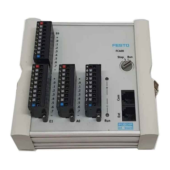
- Page 4 Modulübersicht FEC FC400 Eingang E0.0 bis E0.7 Power LED (Spannungsversor- gung) Eingang E1.0 bis E1.7 Funktionswahlschalter Ausgang A0.0 bis A0.7 Kommunikationsschnittstelle Spannungsversorgung (Com Status LED (Run/Stop/Error) Erweiterungsschnittstelle (Ext) Festo FEC FC400 0110a Deutsch...
- Page 5 Eingang E0.3 oder E1.3; Ausgang A0.3 Eingang E0.4 oder E1.4; Ausgang A0.4 Eingang E0.5 oder E1.5; Ausgang A0.5 Eingang E0.6 oder E1.6; Ausgang A0.6 Eingang E0.7 oder E1.7; Ausgang A0.7 Verteilerleiste 24V DC (intern verbunden) Festo FEC FC400 0110a Deutsch...
- Page 6 Funktionsgruppe in der Steuerung (nicht im Stecker) verbunden. Hinweis Die Verbindungen zwischen den Anschlüssen 1 bis 5 und 6 bis 10 sind für die Spannungsversorgung der Ausgänge geeignet. Die maximale Einzelkontaktbelast- barkeit beträgt 5 A. Festo FEC FC400 0110a Deutsch...
- Page 7 Beachten Sie bitte, dass SM14/15 die Signale Transmit, Receive und RTS/CTS liefern. Werden andere Signale be- nötigt, müssen diese mit Brücken simuliert werden. PS1 SM14: Programmierkabel TTL RS232 + Schnittstellenwandler PS1 SM15: Schnittstellenwandler TTL RS232 ohne Nullmodemkabel Festo FEC FC400 0110a Deutsch...
- Page 8 Wird die Hutschiene dann zur Potenzialausgleichs- schiene, dürfen mehrere IPC FECs auf dieser befestigt wer- den. Die Erdanschlusspunkte in Form von Klemmschuhhal- tern (6,3 mm) sind dann als Funktionserde definiert und können zum Kontaktieren von Schirmungen genutzt wer- den. Festo FEC FC400 0110a Deutsch...
- Page 9 Die Schirme sind beidseitig, großflächig und niederohmig an störungsfreier Erde anzulegen. Dies kann mit der Hut- schienenklammer, die Bestandteil des Erdungssets (Tei- le-Nr.: 526683) ist, erfolgen. Die Gehäuse der verwendeten Hubs müssen ebenfalls niederohmig geerdet werden. Festo FEC FC400 0110a Deutsch...
- Page 10 Isolierwiderstand des IPC FEC zu messen, trennen Sie die Eingangs- und Ausgangsleitungen und die Versorgungs- spannung vom IPC FEC . Führen Sie die Messtests quer über einen gemeinsamen Punkt aller Anschlüsse und der Erdklemme durch. Festo FEC FC400 0110a Deutsch...
- Page 11 Sicherheitsbestimmungen eingehalten werden. Der Anschluss eines Stoßspannungsunterdrückers parallel zu einer induktiven Last reduziert die Erzeugung elektri- scher Störaussendung. Vorsicht Die Betriebsspannung des IPC FEC ist gegen Verpolung geschützt. Überprüfen Sie dennoch die Polarität vor der Inbetriebnahme. Festo FEC FC400 0110a Deutsch...
- Page 12 Status-LED zu dem von Ihnen belegten Eingang leuchten, wenn Ihr Sensor ein “1” Signal lie- fert. 6. ·Starten Sie Ihre Programmiersoftware. Schließen Sie das Programmierkabel SM14 zwischen Ihrem Program- mier-PC (Vorgabe: COM1) und dem FEC FC400 (Schnittstelle COM) an. Festo FEC FC400 0110a Deutsch...
- Page 13 7. Bei Nutzung der FST-Software: 7.1.Legen Sie ein neues Projekt an, wählen Sie den FEC Standard als Steuerung aus. 7.2.Öffnen Sie die IO Konfiguration und fügen Sie ein Eingangs- und ein Ausgangsmodul jeweils mit Adresse 0 ein. 7.3.Fügen Sie ein Programm ein und programmieren...
- Page 14 8.4.Starten Sie die Steuerung. Wenn Sie jetzt am Ein- gang ein Signal anlegen, muss der Ausgang mit der gleichen Adresse zu “1“ werden. Alle übrigen Angaben entnehmen Sie bitte dem Handbuch zum IPC FEC Standard (Teilenr.: 525368) oder der Produkt CD (Teilenr. 189530). Festo FEC FC400 0110a Deutsch...
-
Page 15: Technische Daten
Schutzklasse III. Netzteil nach IEC 742/EN60742/VDE0551/PELV mit mindestens 4 kV Isolationsfe- stigkeit oder Schaltnetzteile mit einer sicheren Trennung im Sinne EN 60950/VDE 0805 notwendig E/A-Anschluss für Zugfederbuchse (SACxx) oder für Schraubklemmbuchse (ZC13-S) EN 61000-6-2, EN 50081-2 Festo FEC FC400 0110a Deutsch... - Page 16 5 ms Potenzialtrennung ja, Optokoppler Zul. Länge der Anschlussleitung max. 30 m Statusanzeige mit LED optional im Stecker Digitale Ausgänge Anzahl Kontakte Transistor Spannung/Strom 24 V DC, max. 400 mA Kurzschlussfest/Überlastfest Lampenfest ja, bis 5 W Festo FEC FC400 0110a Deutsch...
- Page 17 1 kHz Potenzialtrennung in Gruppen ja, jeweils 1 Byte Maximaler Gruppenstrom 3,2 A Schaltspiele größer 20.000.000 Statusanzeige durch LED optional im Stecker Drehschalter Anzahl Positionen STOP/RUN 0 = Stop und 1 ... F = RUN Festo FEC FC400 0110a Deutsch...
- Page 18 Nutzung als universelle Schnitt- 300 ... 115000 Baud, 7N1, 7E1, stelle: EXT 7O1, 8N1, 8E1, 8O1 Statusanzeige Power LED Versorgungsspannungsanzeige - Grün Status LED je nach Status Run - Grün / Stop - Orange /Error - Festo FEC FC400 0110a Deutsch...
- Page 19 Warning Actuators may be unintentionally activated and the IPC FEC Standard may be damaged if assemblies are added or removed while the supply voltage is switched on. Isolate the IPC FEC Standard from the supply voltage before carrying out installation or maintenance work.
- Page 20 Overview of FEC FC400 moduleEnglish Input E0.0 to E0.7 Power LED (supply voltage) Input E1.0 to E1.7 Function selector switch Output A0.0 to A0.7 Communications interface (Com) Supply voltage Extension interface (Ext) Status LED (Run/Stop/Error) Festo FEC FC400 0110a English...
- Page 21 Input E0.3 or E1.3; Output A0.3 Input E0.4 or E1.4; Output A0.4 Input E0.5 or E1.5; Output A0.5 Input E0.6 or E1.6; Output A0.6 Input E0.7 or E1.7; Output A0.7 Distribution bus 24V DC (intern. connected) Festo FEC FC400 0110a English...
- Page 22 (not in the plug). Please note The connections between pins 1 to 5 and 6 to 10 are suitable for supplying voltage to the outputs. The maxi- mum single contact-carrying capacity is 5 A. Festo FEC FC400 0110a English...
- Page 23 Please note that SM14/15 provide Transmit, Receive and RTS/CTS signals. If other signals are required, these must be simulated with links. PS1 SM14: Programming cable TTL RS232 and interface converter PS1 SM15: Interface converter TTL RS232 without nullmodem- cable Festo FEC FC400 0110a English...
- Page 24 IPC FEC’s may be mounted to it. The earth connection points in the form of terminal shoes (6.3 mm) are then defined as functional earths and may be used for screen bonding. Festo FEC FC400 0110a English...
- Page 25 This can be achieved using the top-hat rail which is part of the ground- ing kit (part no 526683). The housings of the hubs being used must also be low-impedance earthed. Festo FEC FC400 0110a English...
- Page 26 IPC FEC, iso- late the input and output lines and the power cable from the IPC FEC and carry out the measurement tests across a common point for all connections and the earthing ter- minal. Festo FEC FC400 0110a English...
- Page 27 Connecting a surge voltage suppressor in parallel with an inductive load reduces the generation of electrical interfer- ence. Caution The IPC FEC supply voltage is protected against polarity reversal. Nevertheless, you should check the polarity prior to implementing. Festo FEC FC400 0110a English...
- Page 28 “1” signal. 6. Start your programming software. Connect the SM14 programming cable between your programming PC (default: COM1) and the FEC FC400 (COM interface). Festo FEC FC400 0110a English...
- Page 29 7. When using the FST software: 7.1.Create a new project and select FEC Standard as the control system. 7.2.Open IO configuration and insert an input and an output module, each with the address 0. 7.3.Insert a program and program it as follows:...
- Page 30 “1”. For all other details, please refer to the manual for the IPC FEC Standard (part no 525369) or the delivered CD with the product (part no 189530. Festo FEC FC400 0110a English...
-
Page 31: Technical Data
4 kV insulation resistance or switched power supply unit with secure isolation within the meaning of EN 60950/VDE 0805 I/O connection For tension spring socket (SAC31) or screw terminal socket (ZC13-S) EN 61000-6-2, EN 50081-2 Festo FEC FC400 0110a English... - Page 32 Potential isolation Yes, optocoupler Permitted length of connecting Max. 30 m cable LED status display Optional at plug Digital outputs Number Contacts Transistor Voltage/current 24 V DC, max. 400 mA Short-circuit and overload resis- tant Festo FEC FC400 0110a English...
- Page 33 Potential isolation in groups Yes, each 1 Byte Maximum group current 3.2 A Switching cycles Greater than 20,000,000 LED staus display Optional at plug Rotary switch Number Positions STOP/RUN 0 = Stop and 1 ... F = RUN Festo FEC FC400 0110a English...
- Page 34 300 ... 9600 Baud, 7N1, 7E1, 7O1, 8N1, 8E1, 8O1 When used as universal interface: 300 ... 115000 Baud, 7N1, 7E1, 7O1, 8N1, 8E1, 8O1 Status display Power LED Supply voltage indicator -green Status LED Run-green/Stop-orange/Error-red Festo FEC FC400 0110a English...
Need help?
Do you have a question about the FEC Standard and is the answer not in the manual?
Questions and answers