
Related Manuals for Festo IPC FEC FC34


Summary of Contents for Festo IPC FEC FC34
- Page 1 FEC Compact Kurz- beschreibung Brief description Typ FEC FC34 type FEC FC34 - Deutsch - English 655846 0206NH...
- Page 2 ..........Edition: 0206NH Original: de © (Festo AG & Co., D-73726 Esslingen, Germany, 2001) Internet: http://www.festo.com E-Mail: service_international@festo.com...
- Page 3 Aktoren können ungewollt aktiviert und der IPC FEC Compact kann beschädigt werden, wenn Baugruppen bei eingeschalteter Spannungsversorgung hinzugefügt oder entfernt werden. Trennen Sie vor Installations- und Wartungsarbeiten den IPC FEC Compact von der Span- nungsversorgung. Festo KBS_FEC FC34- 0206NH Deutsch...
- Page 4 Eingang In 0.0 ... In 0.7 Power LED (Spannungsversor- Gemeinsames Potenzial S0 gung, Betriebsspannung) für In 0.0 ... In 0.7 Status LED (Run/Stop/Error) Eingang In 1.0 ... In 1.3 Gemeinsames Potenzial S1 für In 1.0 ... In 1.3 Festo KBS_FEC FC34- 0109NH Deutsch...
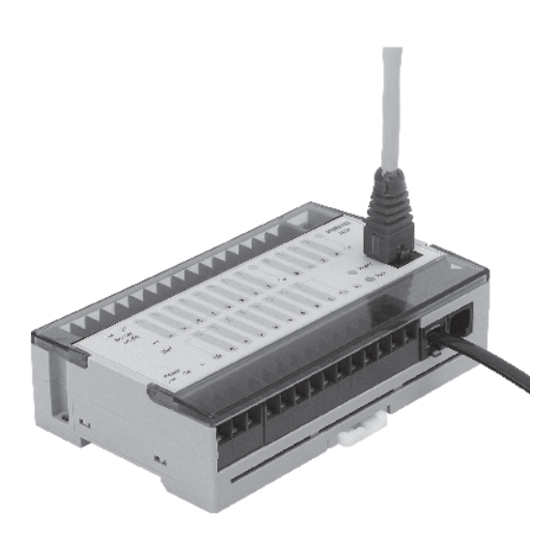
- Page 5 Gemeinsamer Anschluss C0 für Out 0.0 ... Out 0.1 Anschluss für Erweiterung (EXT) Relaisausgänge Out 0.0, Out 0.1 Serielle Schnittstelle (COM) Transistorausgänge Netzwerkanschluss 10BASE T Out 0.2 ... Out 0.7 Link/Traffic LED für Netzwerk- aktivität Festo KBS_FEC FC34- 0206NH Deutsch...
- Page 6 Signale benötigt, müssen diese mit Brücken simu- liert werden. Einsatzmöglichkeiten PS1 SM14 Nutzung als Programmierschnittstelle PS1 SM15 Nutzung mit RS232-Geräten Die Ethernet Schnittstelle (Bezeichnung: TP) ist eine stan- dardisierte Twisted Pair Schnittstelle für Ethernet 10BaseT (10 MBit/s) mit RJ45 Anschluss. Festo KBS_FEC FC34- 0206NH Deutsch...
- Page 7 PS1 SM14: Programmierkabel TTL RS232 + Schnittstellenwandler PS1 SM15: Schnittstellenwandler TTL RS232 Festo KBS_FEC FC34- 0206NH Deutsch...
- Page 8 Mit Hilfe des Verbindungskabels PS1 SM14 kann eine di- rekte Verbindung zwischen IPC FEC FC34 und externem Rechner hergestellt werden. Hierdurch besteht die Mög- lichkeit das Modul IPC FEC FC34 mit eigenen Anwendungs- programmen zu versehen. PS1 SM14: Programmierkabel TTL RS232 + Schnittstellenwandler...
- Page 9 Für TP- und Cross-Over-Kabel sind ausschließlich ge- schirmte Kabel zu verwenden. TP-Kabel des Typs S/STP sind geeignet. Die Schirme sind beidseitig, großflächig und niederohmig an störungsfreier Erde aufzulegen. Die Gehäuse der verwendeten Hubs sind gleichfalls niederoh- mig zu erden. Festo KBS_FEC FC34- 0206NH Deutsch...
- Page 10 Isolierwiderstand des IPC FEC Compact zu messen, tren- nen Sie die Eingangs- und Ausgangsleitungen und die Versorgungsspannungen vom IPC FEC Compact . Führen Sie die Messtests quer über einen gemeinsamen Punkt aller Anschlüsse und der Erdklemme durch. Festo KBS_FEC FC34- 0206NH Deutsch...
- Page 11 Der Anschluss eines Stoßspannungsunterdrückers parallel zu einer induktiven Last reduziert die Erzeugung elektri- scher Störungen. Vorsicht Die Betriebsspannung des IPC FEC ist gegen Verpolung geschützt. Überprüfen Sie dennoch die Polarität vor der Inbetriebnahme. Festo KBS_FEC FC34- 0206NH Deutsch...
- Page 12 Erste Inbetriebnahme des IPC FEC FC34 Allgemeine Inbetriebnahmehinweise Wenn Sie den IPC FEC FC34 erstmals in Betrieb nehmen, beachten Sie bitte die folgenden Hinweise. 1. Beachten Sie die Hinweise zur Sicherheit, Verdrahtung und NOT-AUS. 2. Schließen Sie die 24 V DC Betriebsspannung an den mit Power 24 V und 0 V bezeichneten Klemmen der Klemmleiste an.
- Page 13 0.0, 0.1, Transistorausgänge Out 0.2 ... Out 0.7: 24 V DC 3 S1 Sensor Aktor an Relaisausgang angeschlossen C+, C- Versorgungsspannung Transistorausgänge Funktionserde Aktor an Transistorausgang Netzteil 24 V DC, z. B. PSE3 angeschlossen IPC FEC FC34 Festo KBS_FEC FC34- 0206NH Deutsch...
- Page 14 Ihnen benutzte COM-Schnittstelle um- stellen. 7.5. Schalten Sie die Steuerung auf RUN (die RUN LED muss grün leuchten). Wenn Sie jetzt am Eingang ein Signal anlegen, muss der Ausgang mit der gleichen Adresse zu “1“ werden. Festo KBS_FEC FC34- 0206NH Deutsch...
- Page 15 8. Bei Nutzung der Multiprog Software: 8.1. Legen Sie ein neues Projekt an, benutzen Sie das Template für den IPC FEC FC34. 8.2. Speichern Sie das Projekt unter einem sinnvollen Namen. 8.3. Laden Sie das Projekt zur Steuerung (Sie müssen noch nichts programmiert haben).
-
Page 16: Technische Daten
Wechselspannungskom- ponenten: 30 V / 19,2 V; Verwen- dung eines Netzteils mit einer si- cheren Trennung; siehe unter Schutzklasse Leistungsaufnahme typ. 2,5 W Zulässige Länge der Anschlusslei- 10 m tung für Betriebsspannung Schutzart IP 20 Festo KBS_FEC FC34- 0206NH Deutsch... - Page 17 E/A-Anschluss Schraubklemme Nennquerschnitt 2 x 0,75 mm Anzugsdrehmoment der Schrau- max. 0,5 Nm ben (Schraubklemmen) EN 61000-6-2, EN 50081-2 1)Beim Schalten von “Nicht-PELV-Stromkreisen” über die Relaisausgänge ist die Gesamt- anordnung der Schutzklasse II zuzuordnen. Festo KBS_FEC FC34- 0206NH Deutsch...
-
Page 18: Digitale Eingänge
30 m Statusanzeige mit LED Isolationsfestigkeit gegen interne Bemessungsspannung der Isolie- Systemspannung rung: 50 V AC Die Eingangsspannungen sind aus Stromkreisen der Schutzklasse III zu erzeugen; die Forderung ist bei Nutzung der Sensor Supply Spannung erfüllt. Festo KBS_FEC FC34- 0206NH Deutsch... - Page 19 300.000 Zyklen 100.000 Zyklen Potenzialtrennung ja, Optokoppler Potenzialtrennung in Gruppen eine Gruppe mit 2 Relais eine Gruppe mit 6 Transistoraus- gängen Zul. Länge der Anschlussleitung max. 30 m Maximaler Gruppenstrom 3,2 A; für Transistorausgänge Statusanzeige durch LED Festo KBS_FEC FC34- 0206NH Deutsch...
- Page 20 300 V AC – Transistorausgänge Versorgungsspannungen mit si- cherer Trennung gegen Netzspan- nung; Bemessungsspannung der Isolierung 50 V AC Analogpotenziometer (Trimmer) Anzahl Wertebereich 1 - 63 RUN / STOP - Schalter Anzahl STOP/RUN Softwareabhängig; programmierbar Festo KBS_FEC FC34- 0206NH Deutsch...
- Page 21 Nutzung als universelle Schnitt- 300 ... 9600 Baud, 7N1, 7E1, 7O1, stelle: COM 8N1, 8E1, 8O1 Nutzung als universelle Schnitt- 300...115000 Baud, 7N1, 7E1, stelle: EXT 701, 8N1, 8E1, 801 Die Angaben der jeweiligen Entwicklungsumgebung sind zu beachten. Festo KBS_FEC FC34- 0206NH Deutsch...
- Page 22 CAT5) sind vorzusehen, max. 100 Traffic LED Traffic: LED blinkend Grün Die Angaben der jeweiligen Entwicklungsumgebung sind zu beachten. Statusanzeige Power LED Betriebsspannungsanzeige-Grün Status LED je nach Status Run - Grün / Stop - Orange / Error - Rot Festo KBS_FEC FC34- 0206NH Deutsch...
- Page 23 FEC Compact may be damaged if modules are added or removed while the power supply is switched on. Always disconnect the IPC FEC Compact from the main power supply before starting any installation or maintenance work. Festo KBS_FEC FC34- 0206NH English...
- Page 24 Power LED (main power sup- ply, operating voltage) Common potential S0 for In 0.0 ... In 0.7 Status LED (Run/Stop/Error) Input In 1.0 ... In 1.3 Common potential S1 for In 1,0 ... In 1.3 Festo KBS_FEC FC34- 0109NH English...
- Page 25 Out 0.0 ... Out 0.1 Connection for extension (EXT) Relay outputs Out 0.0, Out 0.1 Serial port (COM) Transistor outputs Network connection 10BASE T Out 0.2 ... Out 0.7 Link/Traffic LED for network activity Festo KBS_FEC FC34- 0206NH English...
- Page 26 Possible uses PS1 SM14 As a programming interface PS1 SM15 With RS232 devices The Ethernet interface (designation: TP) is a standard twi- sted pair interface for Ethernet 10BaseT (10 MBit/s) with RJ45 connection. Festo KBS_FEC FC34- 0206NH English...
- Page 27 PS1 SM14: Programming cable TTL RS232 + interface converter PS1 SM15: TTL/RS232 port adapter Festo KBS_FEC FC34- 0206NH English...
- Page 28 Example connection to an external computer Using the connection cable PS1 SM14, a direct connection can be made between IPC FEC FC34 and an external com- puter. In this way, there is an opportunity to provide the IPC FEC FC34 module with its own application programs.
-
Page 29: Important Installation Instructions
TP cables of type S/STP are suitable. The shielding must be connected at both ends to low impe- dance free earths over as large an area as possible. The casings of the solenoids used must also have low impe- dance earth connections. Festo KBS_FEC FC34- 0206NH English... - Page 30 IPC FEC Compact, first disconnect the input and output cables and the sup- ply voltages from the IPC FEC Compact. Perform the tests across a common point on all the con- nections and the earth terminal. Festo KBS_FEC FC34- 0206NH English...
- Page 31 Caution The operating voltage of the IPC FEC is protected against polarity reversal. You should nevertheless check the polarity before using the module for the first time. Festo KBS_FEC FC34- 0206NH English...
- Page 32 Commissioning the IPC FEC FC34 General instructions on commissioning When you first commission the IPC FEC FC34, please ob- serve the following instructions. 1. Please follow the safety, wiring and emergency stop instructions. 2. Connect the 24 V DC operating voltage to the terminals on the terminal strip labelled as Power 24 V and 0 V.
- Page 33 0.0, 0.1, for transistor outputs Out 0.2 ... Out 0.7: 24 V DC 3 S1 Sensor Actuator connected to relay output C+, C- supply voltage Transistor outputs Functional earth Actuator connected to tran- 24 V DC power pack, e.g. PSE3 sistor output IPC FEC FC34 Festo KBS_FEC FC34- 0206NH English...
- Page 34 7.5. Switch the controller to RUN (the RUN LED must light up green). If you now apply a signal at the input, the output with the same address must switch to “1“. Festo KBS_FEC FC34- 0206NH English...
- Page 35 8.4. Start the controller. If you now apply a signal at the input, the output with the same address must switch to “1“. All remaining data can be found in manual for the IPC FEC Compact or the product CD. Festo KBS_FEC FC34- 0206NH English...
-
Page 36: Technical Specifications
V; If you are using a power pack with reliable isolation; see under Protection class Power consumption typically 2,5 W Permitted length of connecting 10 m cable for operating voltage Degree of protection IP 20 Festo KBS_FEC FC34- 0206NH English... -
Page 37: General Information
2 x 0.75 mm Tightening torque for screws max. 0.5 Nm (screw-type terminals) EN 61000-6-2, EN 50081-2 1)When switching from “non-PELV circuits” via the relay outputs, the complete unit is to be assigned to protection class II. Festo KBS_FEC FC34- 0206NH English... -
Page 38: Digital Inputs
Insulation resistance against in- Rated voltage of insulation: 50 V ternal system voltage The input voltages should be generated from electrical circuits from protection class III. This requirement is fulfilled if the sensor supply voltage is used. Festo KBS_FEC FC34- 0206NH English... -
Page 39: Digital Outputs
Electrical isolation yes, optocoupler Electrical isolation between one group with 2 relays groups one group with 6 transistor out- puts Permitted length of connecting max. 30 m cable Maximum group current 3.2 A; for transistor outputs Festo KBS_FEC FC34- 0206NH English... - Page 40 Supply voltages with safe isola- – Transistor outputs tion against supply voltage, rated voltage of the insulation 50 V AC Analog potentiometer (trimmer) Number Range of values 1 - 63 RUN / STOP switch Number STOP/RUN Software-dependent; programmable Festo KBS_FEC FC34- 0206NH English...
-
Page 41: Serial Ports
300 ... 9600 baud, 7N1, 7E1, 7O1, 8N1, 8E1, 8O1 As a universal interface: EXT 300 to 115000 Baud, 7N1, 7E1, 701, 8N1, 8E1, 801 The requirements of the relevant development environment must be observed. Festo KBS_FEC FC34- 0206NH English... - Page 42 The requirements of the relevant development environment must be observed. Status display Power LED Operating voltage display - Green Status LED According to the status: Run - Green / Stop - Orange / Error - Red Festo KBS_FEC FC34- 0206NH English...
Need help?
Do you have a question about the IPC FEC FC34 and is the answer not in the manual?
Questions and answers