
Related Manuals for Festo FEC Compact


Summary of Contents for Festo FEC Compact
- Page 1 FEC Compact Kurz- beschreibung Brief description Typ FEC FC30 type FEC FC30 - Deutsch - English 655845 0206NH...
- Page 2 ..........Edition: 0206NH Original: de © (Festo AG & Co., D-73726 Esslingen, Germany, 2001) Internet: http://www.festo.com E-Mail: service_international@festo.com...
- Page 3 Aktoren können ungewollt aktiviert und der IPC FEC Compact kann beschädigt werden, wenn Baugruppen bei eingeschalteter Spannungsversorgung hinzugefügt oder entfernt werden. Trennen Sie vor Installations- und Wartungsarbeiten den IPC FEC Compact von der Span- nungsversorgung. Festo KBS-FEC FC30- 0206NH Deutsch...
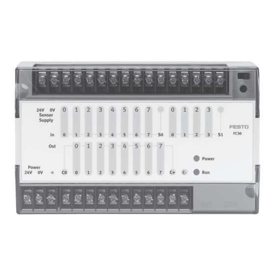
- Page 4 Sensorversorgung 0 V RUN/STOP Schalter Eingang In 0.0 ... In 0.7 Analogpotenziometer Gemeinsames Potenzial S0 (Trimmer) für In 0.0 ... In 0.7 Power LED (Spannungsversor- Eingang In 1.0 ... In 1.3 gung, Betriebsspannung) Status LED (Run/Stop/Error) Festo KBS-FEC FC30- 0109NH Deutsch...
- Page 5 Relaisspulen Funktionserde Ausgangsversorgung C- (0 V) Gemeinsamer Anschluss C0 für Out 0.0 ... Out 0.1 Anschluss für Erweiterung (EXT) Relaisausgänge Out 0.0, Out 0.1 Serielle Schnittstelle (COM) Transistorausgänge Out 0.2 ... Out 0.7 Festo KBS-FEC FC30- 0109NH Deutsch...
- Page 6 Für SM14/SM15 stehen die Signale Transmit, Receive und RTS/CTS zur Verfügung. Werden andere Signale benötigt, müssen diese mit Brücken simuliert werden. Einsatzmöglichkeiten PS1 SM14 Nutzung als Programmierschnittstelle PS1 SM15 Nutzung mit RS232-Geräten PS1 SM14: Programmierkabel PS1 SM15: Schnittstellenwandler TTL RS232 Festo KBS-FEC FC30- 0206NH Deutsch...
- Page 7 Verbindung zwischen IPC FEC FC30 und externem Rechner hergestellt werden. Hierdurch besteht die Mög- lichkeit das Modul IPC FEC FC30 mit eigenen Anwendungs- programmen zu versehen. PS1 SM14 Programmierkabel Modul IPC FEC FC30 Externer Rechner Festo KBS-FEC FC30- 0206NH Deutsch...
- Page 8 EN 60950 / VDE 0805 sind zulässig. Das Netzteil PS1 PSE3 erfüllt die genannten Forderungen. Die eingesetzten Leistungsrelais erlauben das direkte Schalten von Netzspannungen der Überspannungskatego- rie II, die Isolationsfestigkeit zwischen Kontakten und Spule beträgt 3000 V AC. Festo KBS-FEC FC30- 0206NH Deutsch...
- Page 9 Sollte es nötig sein, die max. Isolationsspannung und den Isolierwiderstand des IPC FEC-Compact zu messen, tren- nen Sie die Eingangs- und Ausgangsleitungen und die Versorgungsspannungen vom IPC FEC Compact. Führen Sie die Messtests quer über einen gemeinsamen Punkt aller Anschlüsse und der Erdklemme durch.
- Page 10 Sie verhindern, dass solche Lasten gleichzei- tig aktiviert werden. Hinweis Für NOT-AUS-Funktionen sollten die Ausgangslasten mit einem Schalter außerhalb des IPC FEC Compact, der die Lastspannung von den Ausgangsklemmen trennt, ausgeschaltet werden. Wenn Sie einen NOT-AUS Schaltkreis anschließen, ach- ten Sie bitte darauf, dass nationale Verdrahtungs- und Sicherheitsbestimmungen eingehalten werden.
- Page 11 Ihnen belegten Eingang muss leuchten, wenn Ihr Sensor ein “1” Signal liefert. 6. •Starten Sie Ihre Programmiersoftware. Schließen Sie das Programmierkabel SM14 zwischen Ihrem Program- mier-PC (Vorgabe: COM1) und dem IPC FEC FC30 (Schnittstelle COM) an. Festo KBS-FEC FC30- 0206NH Deutsch...
- Page 12 0.0, 0.1, Transistorausgänge Out 0.2 ... Out 0.7: 24 V DC Sensor Aktor an Relaisausgang angeschlossen C+, C- Versorgungsspannung Transistorausgänge Funktionserde Aktor an Transistorausgang Netzteil 24 V DC, z. B. PSE3 angeschlossen IPC FEC FC30 Festo KBS-FEC FC30- 0206NH Deutsch...
- Page 13 Ihnen benutzte COM-Schnittstelle um- stellen. 7.5. Schalten Sie die Steuerung auf RUN (die RUN LED muss grün leuchten). Wenn Sie jetzt am Eingang ein Signal anlegen, muss der Ausgang mit der gleichen Adresse zu “1“ werden. Festo KBS-FEC FC30- 0206NH Deutsch...
- Page 14 8.4. Starten Sie die Steuerung. Wenn Sie jetzt am Ein- gang ein Signal anlegen, muss der Ausgang mit der gleichen Adresse zu “1“ werden. Alle übrigen Angaben entnehmen Sie bitte dem Handbuch zum IPC FEC Compact (P.BE-FEC-C-SYS...) oder der Produkt CD (Teile-Nr. 189530). Festo KBS-FEC FC30- 0206NH Deutsch...
-
Page 15: Technische Daten
24 V DC +20 %/-15 %; absolute Grenzwerte unter Berücksichti- gung der Wechselspannungskom- ponenten: 30 V/19,2 V; Verwen- dung eines Netzteils mit einer si- cheren Trennung; siehe unter Schutzklasse Leistungsaufnahme typ. 2,5 W Zul. Länge der Anschlussleitung 10 m für Betriebsspannung Festo KBS-FEC FC30- 0206NH Deutsch... - Page 16 EN 60950/VDE 0805 notwendig E/A-Anschluss Schraubklemme Nennquerschnitt 2 x 0,75 mm Anzugsdrehmoment der Schrau- max. 0,5 Nm ben (Schraubklemmen) EN 61000-6-2, EN 50081-2 Bei Schalten von Nicht-PELV-Stromkreisen über die Relaisausgänge ist die Gesamtan- ordnung der Schutzklasse II zuzuordnen. Festo KBS-FEC FC30- 0206NH Deutsch...
-
Page 17: Digitale Eingänge
30 m Statusanzeige mit LED Isolationsfestigkeit gegen interne Bemessungsspannung der Isolie- Systemspannung rung: 50 V AC Die Eingangsspannungen sind aus Stromkreisen der Schutzklasse III zu erzeugen; die Forderung ist bei Nutzung der Sensor Supply Spannung erfüllt. Festo KBS-FEC FC30- 0206NH Deutsch... - Page 18 – 2 A 300.000 Zyklen 100.000 Zyklen Potenzialtrennung ja, Optokoppler Potenzialtrennung in Gruppen eine Gruppe mit 2 Relais eine Gruppe mit 6 Transistoraus- gängen Zul. Länge der Anschlussleitungen max. 30 m Maximaler Gruppenstrom 3,2 A; für Transistorausgänge Festo KBS-FEC FC30- 0206NH Deutsch...
- Page 19 Isolierung: 300 V AC – Transistorausgänge Versorgungsspannung mit siche- rer Trennung gegen Netzspan- nung; Bemessungsspannung der Isolierung 50 V AC Analogpotenziometer (Trimmer) Anzahl Wertebereich 1 - 63 RUN / STOP - Schalter Anzahl STOP/RUN Softwareabhängig; programmierbar Festo KBS-FEC FC30- 0206NH Deutsch...
- Page 20 EXT 7O1, 8N1, 8E1, 8O1 Die Angaben der jeweiligen Entwicklungsumgebung sind zu beachten. Statusanzeige Power LED Betriebsspannungsanzeige - Grün Status LED je nach Status Run - Grün / Stop - Orange / Error - Rot Festo KBS-FEC FC30- 0206NH Deutsch...
- Page 21 Warning Actuators may be unintentionally activated and the IPC FEC Compact may be damaged if modules are added or removed while the power supply is switched on. Always disconnect the IPC FEC Compact from the main power supply before starting any installation or maintenance work.
- Page 22 Input In 0.0 ... In 0.7 Analog potentiometer (trimmer) Common potential S0 for In 0.0 ... In 0.7 Power LED (main power sup- ply, operating voltage) Input In 1.0 ... In 1.3 Status LED (Run/Stop/Error) Festo KBS-FEC FC30- 0109NH English...
- Page 23 Functional earth Output supply C- (0 V) Common connection C0 for Out 0.0 ... Out 0.1 Connection for extension (EXT) Relay outputs Out 0.0, Out 0.1 Serial port (COM) Transistor outputs Out 0.2 ... Out 0.7 Festo KBS-FEC FC30- 0109NH English...
- Page 24 SM14/SM15. If other signals are required, they must be simulated using jumpers. Possible uses PS1 SM14 As a programming interface PS1 SM15 With RS232 devices PS1 SM14: Programming cable PS1 SM15: TTL/RS232 port adapter Festo KBS-FEC FC30- 0206NH English...
- Page 25 The PS1 SM14 connecting cable can be used to link the IPC FEC FC30 directly to an external computer, thus allow- ing the IPC FEC FC30 module to have its own application programs. PS1 SM14 programming cable IPC FEC FC30 module External computer Festo KBS-FEC FC30- 0206NH English...
-
Page 26: Important Installation Instructions
The PS1 PSE3 power pack fulfils all the above require- ments. The power relays used allow mains voltages from overvol- tage category II to be switched directly, and the insulation resistance between contacts and coil is 3000 V AC. Festo KBS-FEC FC30- 0206NH English... - Page 27 When using inductive loads take necessary precautions to eliminate voltage trends. If it proves necessary to measure the maximum insulation voltage and dielectric resistance of the IPC FEC Compact, first disconnect the input and output cables and the sup- ply voltages from the IPC FEC Compact.
- Page 28 Connecting a surge suppresser in parallel to an inductive load reduces the electrical interference that is generated. Caution The operating voltage of the IPC FEC Compact is pro- tected against polarity reversal. You should neverthe- less check the polarity before using the module for the first time.
- Page 29 “1” signal. 6. Start your programming software. Connect the SM14 programming cable between your programming PC (ideally at COM1) and the IPC FEC FC30 (COM port). Festo KBS-FEC FC30- 0206NH English...
- Page 30 0.0, 0.1, for transistor outputs Out 0.2 ... Out 0.7: 24 V DC Sensor Actuator connected to relay output C+, C- supply voltage Transistor outputs Functional earth Actuator connected to tran- 24 V DC power pack, e.g. PSE3 sistor output IPC FEC FC30 Festo KBS-FEC FC30- 0206NH English...
- Page 31 7.5. Switch the controller to RUN (the RUN LED must light up green). If you now apply a signal at the input, the output with the same address must switch to “1“. Festo KBS-FEC FC30- 0206NH English...
- Page 32 “1“. All further information can be found in the manual for the IPC FEC Compact (P.BE-FEC-C-SYS ..) or on the product CD (part no. 189530). Festo KBS-FEC FC30- 0206NH English...
-
Page 33: Technical Specifications
AC voltage components: 30 V/19.2 V; If you are using a power pack with reliable isolation; see under Protection class Power consumption typically 2,5 W Permitted length of connecting 10 m cable for operating voltage Festo KBS-FEC FC30- 0206NH English... -
Page 34: General Information
2 x 0.75 mm Tightening torque for screws max. 0.5 Nm (screw-type terminals) EN 61000-6-2, EN 50081-2 The entire device should be assigned to class II if non-PELV electrical circuits are switched via the relay outputs. Festo KBS-FEC FC30- 0206NH English... -
Page 35: Digital Inputs
Insulation resistance against in- Rated voltage of insulation: 50 V ternal system voltage The input voltages should be generated from electrical circuits from protection class III. This requirement is fulfilled if the sensor supply voltage is used. Festo KBS-FEC FC30- 0206NH English... - Page 36 Electrical isolation yes, optocoupler Electrical isolation between one group with 2 relays groups one group with 6 transistor out- puts Permitted length of connecting max. 30 m cables Maximum group current 3.2 A; for transistor outputs Festo KBS-FEC FC30- 0206NH English...
- Page 37 Supply voltage with reliable isola- – Transistor outputs tion from mains voltage; rated voltage of insulation: 50 V AC. Analog potentiometer (trimmer) Number Range of values 1 - 63 RUN / STOP switch Number STOP/RUN Software-dependent; programmable Festo KBS-FEC FC30- 0206NH English...
-
Page 38: Serial Ports
The specifications from the development environment should be observed. Status display Power LED Operating voltage display - Green Status LED According to the status: Run - Green / Stop - Orange / Error - Red Festo KBS-FEC FC30- 0206NH English...
Need help?
Do you have a question about the FEC Compact and is the answer not in the manual?
Questions and answers