Festo CP Factory Manual
Application module idrilling
Hide thumbs
Also See for CP Factory:
- Manual (126 pages) ,
- Original operating instructions (90 pages) ,
- Manual (115 pages)

Subscribe to Our Youtube Channel
Related Manuals for Festo CP Factory


Summary of Contents for Festo CP Factory
- Page 1 ® CP Factory / CP Lab Manual application module iDrilling Festo Didactic CP Factory / CP Lab 06/2017...
- Page 2 The training company and/or the training staff must ensure that the trainees observe the safety precautions. Festo Didactic accepts no liability for injury or harm to trainees, the training company and/or any third parties occurring when the installation is used for any purpose apart from training, except Festo Didactic has caused such injury or harm intentionally or by grossly negligence.
-
Page 3: Table Of Contents
5.3.3 Proximity switch (Z-axis)____________________________________________________________ 27 5.4 Adjusting the one-way flow control valves_________________________________________________ 29 5.5 Visual inspection _____________________________________________________________________ 30 6 Operation _______________________________________________________________________________ 31 6.1 General operating instructions __________________________________________________________ 31 © Festo Didactic CP Factory / CP Lab ° application module drilling... - Page 4 6.2 Sequence description of the application module drilling _____________________________________ 31 6.3 Setting the application module drilling at HMI _____________________________________________ 35 6.4 Transitions of the application module ____________________________________________________ 37 6.5 Parameter of application _______________________________________________________________ 38 © Festo Didactic CP Factory / CP Lab ° application module drilling...
-
Page 5: General Safety Instructions
Protective earth must always be connected first (before voltage), and must always be disconnected last (after voltage). If not otherwise specified in the technical data, the device is not equipped with an integrated fuse. © Festo Didactic CP Factory / CP Lab ° application module drilling... -
Page 6: Pictograms
Failure to pay attention to this symbol may result in damages to the machine or to its surroundings. Information This symbol indicates operational tips and especially useful directions. This symbol assists you to make optimal use of all of your machine’s functions. © Festo Didactic CP Factory / CP Lab ° application module drilling... -
Page 7: Safety Sockets
According to EN 60204-1 (VDE 0113-1) part 8.2.8, a supply cable with an additional protective conductor is required for the supply of the CP factory installations. Since a leakage current of >10mA can flow depending on the configuration, an additional protective conductor with 10mm² is necessary. -
Page 8: Handling The System
All screw connections released during maintenance, inspection or repair work must be checked to ensure correct re-tightening. © Festo Didactic CP Factory / CP Lab ° application module drilling... -
Page 9: Organizational Measures
All persons who have been entrusted to work with the system undertake to complete the following steps before beginning work: Read the chapter concerning safety and the warnings in this manual Observe the basic regulations on occupational safety and accident prevention. © Festo Didactic CP Factory / CP Lab ° application module drilling... -
Page 10: Introduction
Catastrophes as a result of foreign bodies and vis major. Festo Didactic herewith rules out any liability for damage or injury to trainees, the training company and/or other third parties which may occur during the use/operation of the system other than purely in a training situation, unless such damage has been caused intentionally or due to gross negligence by Festo Didactic. -
Page 11: Technical Data
600 kPA ( 6 bar) Power supply 24 V DC, 4.5 A L x W x H 382 x 215 x 574 mm Weight approx 5 kg Digital inputs Digital output © Festo Didactic CP Factory / CP Lab ° application module drilling... -
Page 12: Design And Function
The stations are not to be picked up by or even under the mounted feet – increased risk of becoming trapped or contused. Check the station for any possible damaged once unpacked. The carrier and Festo Didactic are to be notified immediately of any damage. -
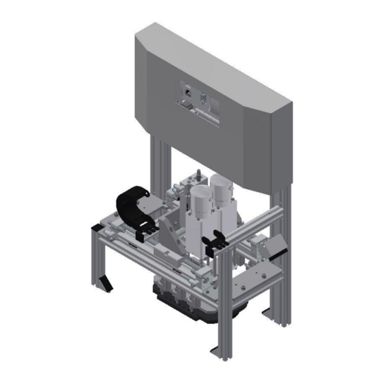
Page 13: The Application Module Idrilling
The drilling unit will make 2 drilled holes into the left part of the housing lower part. Then the drilling unit will be moved to the right by an X-axis, and the additional 2 holes will be drilled. © Festo Didactic CP Factory / CP Lab ° application module drilling... - Page 14 Workpiece request (no upper part available) SOEZ-LLK-SE-2,0-M4 165360 Workpiece request (workpiece available) SOEZ-LLK-SE-2,0-M4 165360 Start-up current limiter 2 150768 Drill 2 drill construction kit 656874 Drill 1 drill construction kit 656874 © Festo Didactic CP Factory / CP Lab ° application module drilling...
-
Page 15: Function
Then the X-axis moves to the right position and the two right drilling holes are drilled. After that, the carrier leaves the application module iDrilling. © Festo Didactic CP Factory / CP Lab ° application module drilling... -
Page 16: Process Description
9. Depending on the drill program, the X axis returns to its initial position 10. The application program is finished, the stopper switches downwards and the goods carrier leaves the station. For parameters for the sequence, see chapter Operation. © Festo Didactic CP Factory / CP Lab ° application module drilling... -
Page 17: Electrical Connections
0= Back cover already available +VN-BG7 KF1 / X2:7 I0.7 Not used I1.0 Not used I1.1 Not used I1.2 Not used I1.3 Not used I1.4 Emergency stop active +VN-XD1:24NA I1.5 © Festo Didactic CP Factory / CP Lab ° application module drilling... - Page 18 +VN-QA4:IN KF1 / X4:3 Q0.3 Z-axis upward +VN-MB5 KF1 / X4:4 Q0.4 Z-axis downward +VN-MB6 KF1 / X4:5 Q0.5 Q0.6 Z-axis clamping open +VN-MB7 KF1 / X4:6 Reserve © Festo Didactic CP Factory / CP Lab ° application module drilling...
-
Page 19: Start Up
All components, pipe connections and wirings are marked clearly in order to guarantee an unproblematic re- establishment of all connections. The graphics for the pneumatic and the electric connections are described exemplarily as follows. © Festo Didactic CP Factory / CP Lab ° application module drilling... -
Page 20: Connection Of Application Module
Put in slot nuts Then you install the application module. The slot nuts must be placed now under the mounting brackets so that the screws can be fixed. © Festo Didactic CP Factory / CP Lab ° application module drilling... - Page 21 Please make sure that the workpieces can be transferred correctly like here at the application module magazine. Once the position has been fixed, you only have to tighten the screws and to put the covers on the mounting brackets. © Festo Didactic CP Factory / CP Lab ° application module drilling...
-
Page 22: Pneumatic Port Of Application Module
You only have to plug the tube (nominal size 4) into the QS plug. Pneumatic connection of the application module 5.2.3 Electrical connection of application modules See design and Function © Festo Didactic CP Factory / CP Lab ° application module drilling... -
Page 23: Adjusting The Sensors
Locking screw for clamping/adjusting the sensor socket vertically Sensor socket with sensor and light deflection/ 165360 (SOEZ-LLK-SE-2,0-M4) Sensor holder / request inserted correctly Sensor holder/ request cover available Sensor holder / request basic body available © Festo Didactic CP Factory / CP Lab ° application module drilling... - Page 24 You have to do this with all 3 light barriers. Please pay special attention to the corresponding function. Documents Data sheets / Operating instructions Fibre-optic unit SOEG_L (165327) and through-beam sensor SOEZ-LLK-SE-2,0-M4 (165360) © Festo Didactic CP Factory / CP Lab ° application module drilling...
-
Page 25: Proximity Switch (X-Axis Cylinder)
The proximity switches are used for checking the end position of the cylinder for the X-axis. The proximity switches react to a permanent magnet on the piston of the cylinder. © Festo Didactic CP Factory / CP Lab ° application module drilling... - Page 26 5. Tighten the locking screw of the proximity switch with an Allen key SW1.3. 6. Please check the position of the proximity switch by repeated test runs of the cylinder. Documents Data sheets / operating instructions Proximity switch SME-10 (173210) © Festo Didactic CP Factory / CP Lab ° application module drilling...
-
Page 27: Proximity Switch (Z-Axis)
Z-axis bottom / 173210 (SME-10-KL-LED-24) The proximity switches are used for checking the end position of the Z-axis. The proximity switches react to a permanent magnet on the piston of the cylinder. © Festo Didactic CP Factory / CP Lab ° application module drilling... - Page 28 5. Tighten the locking screw of the proximity switch with an Allen key SW1.3. 6. Please check the position of the proximity switch by repeated test runs of the cylinder. Documents Data sheets / operating instructions Proximity switch SME-10-KL-LED-24 (173210) © Festo Didactic CP Factory / CP Lab ° application module drilling...
-
Page 29: Adjusting The One-Way Flow Control Valves
The piston is clamped between air cushions by free supply air and throttled exhaust air (improvement of the operating behaviour even if the load changes). © Festo Didactic CP Factory / CP Lab ° application module drilling... -
Page 30: Visual Inspection
(cracks, loose connections etc.) the function of the Emergency-Stop settings Please make sure that all damages discovered are removed before starting the application module! © Festo Didactic CP Factory / CP Lab ° application module drilling... -
Page 31: Operation
If the application module is mounted on a CP Lab transport system or on a CP Factory basic module, the general operation is described in these manuals. All application-specific information is described in the application module manual. - Page 32 Operation Automatic Mode sequence step 1-6 © Festo Didactic CP Factory / CP Lab ° application module drilling...
- Page 33 Operation Automatic Mode sequence step 7-12 © Festo Didactic CP Factory / CP Lab ° application module drilling...
- Page 34 Operation Automatic Mode sequence step 14 © Festo Didactic CP Factory / CP Lab ° application module drilling...
-
Page 35: Setting The Application Module Drilling At Hmi
To set the application module, the application module must be set to setup mode. 1. On the Start screen, click Setup Change to setup page (1) and select application (2) © Festo Didactic CP Factory / CP Lab ° application module drilling... - Page 36 Front cover available: Sensor VN_BG4 indicator (lights up green when front cover is present) Back cover available: Sensor VN_BG8 indicator (lights up green when rear cover is present) © Festo Didactic CP Factory / CP Lab ° application module drilling...
-
Page 37: Transitions Of The Application Module
The transitions are located in the Parameters submenu The transitions can be displayed or changed here. The transitions are used in the default mode, see also the following chapter. © Festo Didactic CP Factory / CP Lab ° application module drilling... -
Page 38: Parameter Of Application
Limitation: 1-3, value: 1, constant 122 Drill both sides 1 Program number [-] Limitation: 1-3, value: 3, constant 123 Drill Program number [-] individually Limitation: 1-3, value: 1, variable © Festo Didactic CP Factory / CP Lab ° application module drilling... - Page 39 Operation Festo Didactic SE Rechbergstraße 3 73770 Denkendorf Germany Internet: www.festo-didactic.com E-mail: did@de.festo.com © Festo Didactic CP Factory / CP Lab ° application module drilling...
Need help?
Do you have a question about the CP Factory and is the answer not in the manual?
Questions and answers