Sign In
Upload
Manuals
Brands
Festo Manuals
Industrial Electrical
FB16
Festo FB16 Manuals
Manuals and User Guides for Festo FB16. We have
1
Festo FB16 manual available for free PDF download: Electronic Manual
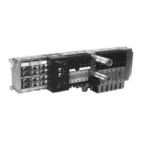
Festo FB16 Electronic Manual (190 pages)
Valve terminal type 03/05, Field bus connection
Brand:
Festo
| Category:
Industrial Electrical
| Size: 1.63 MB
Table of Contents
Table of Contents
5
Vifb16
2
Service
16
Chapter 1 SYSTEM SUMMARY
17
1. System Summary
18
System Structure
19
System Summary
19
Type 03: Description of Components
21
Type 05: Description of Components
25
Description of the Functions
27
Chapter 2 FITTING
29
Fitting the Components
30
Input/Output Modules
32
End Plates
34
Hat Rail Clamping Unit (Type 03)
36
Type 03 Fitting the Valve Terminal
37
Wall Fitting (Type 03)
37
Hat Rail Fitting (Type 03)
38
Type 03
39
Type 05 Fitting the Valve Terminal
40
Wall Fitting (Type 05)
40
Chapter 3 INSTALLATION
43
General Connection Principles
44
Cable Selection - Field Bus Cable
46
Cable Selection - Operating Voltages
46
Connecting the Cables to the Plugs/Sockets
47
Field Bus Node
49
Opening and Closing the Node
49
Configuring the Valve Terminal
51
(Connection Point)
53
Setting the Field Bus Address
53
(Error Reaction of the Outputs)
55
Setting "HOLD/STOP
55
Type 03 Connecting the Operating Voltages
56
Type 05 Connecting the Operating Voltages
63
Connecting the Field Bus
70
Connection Instructions Fipio/Telemecanique
73
Cable Termination/Bus Termination
75
Connecting the Input Modules
76
Pin Assignment
78
Connecting the Output Modules
79
Chapter 4 COMMISSIONING
83
4. Commissioning
84
Basic Principles of Configuration and Addressing
87
General
87
Switching on the Operating Voltage
88
Calculating the Configuration Data
89
Calculating the Number of Inputs/Outputs Type
90
Calculating the Number of Inputs/Outputs Type
91
Address Assignment of the Valve Terminal
92
General (Types 03 and 05)
92
Commissioning
87
Basic Rule 1
93
Basic Rule 2
96
Address Assignment after Extension Conversion
97
General Notes on Configuring for Valve Terminals
101
Field Bus Address (Connecting Point)
101
FIPIO Standard Profile for Festo Valve Terminals
103
Installation under XTEL (from V52)
104
Versions of Software Required
104
Starting the Configuration Software
105
Entering the Valve Terminal
106
Device Family
108
Allocation to the STD_P Device Family
108
Configuring the Valve Terminal as Base Device FSD C8
109
Defining the Parameters of the Valve Terminal
110
Programming under Xtel (V52)
113
Available Objects
113
Addressing the Inputs
115
Addressing the Outputs
116
Addressing Examples
117
April/Software Orphee Controllers
121
FIPIO Standard Profile for Festo
123
Valve Terminals
123
Commissioning under
124
Selecting the Controller and the Processor
124
Software Version Required
124
Entering the Valve Terminal
125
Configuring Valve Terminals
126
Programming under ORPHEE
129
Image of the Inputs of a Valve Terminal
130
Image of the Outputs of the Valve Terminal
132
Addressing Example
133
Valve Terminal
133
Error Word of the Input Table
136
(Hold/Stop)
137
Shutdown Behaviour of Outputs
137
Chapter 5 DIAGNOSIS and ERROR TREATMENT
139
5. Diagnosis and Error Treatment
140
Summary of Diagnostic Possibilities
141
On-The-Spot Diagnosis
142
LED Displays
142
Field Bus Node
142
Valves
144
Input/Output Modules
146
Testing the Valves
147
Starting the Test Routine
148
Stopping the Test Routine
148
Status Bits
149
Position of Status Bits
151
DIAGNOSIS VIA the FIELD BUS (with XTEL)
152
General
152
System Bits and System Words
153
STATUSA Module Diagnosis
154
Validity of the Inputs ("RD" Register)
156
XTEL Diagnosis Tools (Setting Tools)
157
Diagnose Via
158
System Diagnosis
158
Error Treatment
158
Short Circuit/Overload at
160
Evaluating the Error Word of the Input Table
162
Error Treatment
164
Technical Appendix
166
General
167
Technical Specifications
167
VIFB16 - 03/05 Appendix A
167
Operating Voltage of Electronic Components and Inputs
168
Operating Voltage of Outputs/Valves
168
Electronic Input Modules
169
Electronic Output Modules
169
Electromagnetic Compatibility (EMC
170
Field Bus
170
Cable Length and Cross Section
171
Calculating with Graphs
172
Calculating with a Formula
174
Examples of Circuitry
176
Operating Voltage Connection Type 03
176
Operating Voltage Connection Type 05
177
4-Input Module PNP
178
8-Input Module PNP
179
4-Input Module NPN
180
8-Input Module NPN
181
4-Output Module PNP
182
Advertisement
Advertisement
Related Products
Festo IPC FEC FC34
Festo FEC Standard
Festo IPC FEC FC400
Festo FEC Compact
Festo IPC FEC FC30
Festo FB6
Festo FB13
Festo FLSM-6-L
Festo FSLM-8-R
Festo FDG-50
Festo Categories
Industrial Equipment
Control Unit
Controller
Touch terminals
DC Drives
More Festo Manuals
Login
Sign In
OR
Sign in with Facebook
Sign in with Google
Upload manual
Upload from disk
Upload from URL