Festo CPX-FB33 Operating Instructions Manual
Hide thumbs
Also See for CPX-FB33:
- Manual (160 pages) ,
- Electronics description (134 pages) ,
- Operating instructions manual (40 pages)

Related Manuals for Festo CPX-FB33


Summary of Contents for Festo CPX-FB33
- Page 1 CPX-(M)-FB33/34/35/43/44/45 Bus node Operating instructions 548760 548760 2020-04e [8106909]...
- Page 2 Translation of the original instructions ® PI PROFIBUS PROFINET is a registered trademark of its respective trademark holder in certain coun- tries. Festo — CPX-(M)-FB33/34/35/43/44/45 — 2020-04e...
-
Page 3: Table Of Contents
Diagnostics via status bits.................... 23 10.4 Diagnostics via the I/O diagnostics interface (STI)............24 10.5 Diagnostics via CPX-MMI....................24 10.6 Diagnostics via CPX-FMT....................24 10.7 Diagnostics via PROFINET..................... 24 Disposal........................25 Technical data......................26 12.1 General..........................26 12.2 Network.........................27 Festo — CPX-(M)-FB33/34/35/43/44/45 — 2020-04e... -
Page 4: About This Document
About this document About this document Applicable Documents All available documents for the product è www.festo.com/sp. Document Contents CPX system description (CPX-SYS-...) Detailed information on the CPX terminal Brief instructions for bus node Essential information on the product Operating instructions for bus node Detailed information on the product Tab. -
Page 5: Intended Use
Accessories è www.festo.com/catalogue. – Spare parts è www.festo.com/spareparts. Service Contact your regional Festo contact person if you have technical questions è www.festo.com. Product overview Function The bus node as a device in a PROFINET IO network establishes the connection to the higher-order controller. The PROFINET communicates in real-time with the Real-Time Protocol (RT) or the Isochron- ous Real-Time Protocol (IRT). - Page 6 The current GSDML file is required to be able to use all functions of the bus node. The current GSDML file for CPX terminals is located in the Festo Support Portal: è www.festo.com/sp Festo — CPX-(M)-FB33/34/35/43/44/45 — 2020-04e...
-
Page 7: Configuration
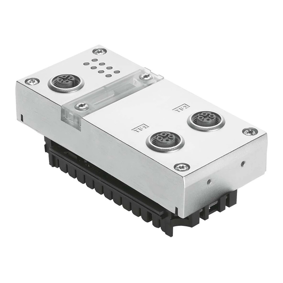
Product overview Consult your local Festo repair service if you have any questions or technical problems. Configuration 5.2.1 Product design 1 LED Displays 4 DIL Switch 2 Memory card (only for FB33/34/35) 5 Service interface 3 Network connection 6 Product labelling Fig. -
Page 8: Led Displays
Tab. 3 Required revision numbers for using the functions The revision numbers of the hardware and software for the bus node can be checked with the control software, the Festo Maintenance Tool (FMT) or the Festo Field Device Tool (FFT). 5.2.3... -
Page 9: Control Elements
2: OFF (factory set- 8 bytes I/8 bytes O ting) 1: OFF Status bits Data field size: 2: ON switched on 16 bytes I/16 bytes O 1: ON I/O diagnostics interface Data field size: 2: OFF switched on 32 bytes I/32 bytes O Festo — CPX-(M)-FB33/34/35/43/44/45 — 2020-04e... - Page 10 The various bus node revisions are only compatible with the corresponding memory card: Memory card Bus bus node revision number CPX-SK From Rev 07 CPX-SK-2 From Rev 12 CPX-SK-3 From Rev 30 Tab. 7 Compatibility of the memory cards depending on the bus node revision Festo — CPX-(M)-FB33/34/35/43/44/45 — 2020-04e...
-
Page 11: Connecting Elements
Product overview 5.2.5 Connecting Elements Pin allocation of the network interface of the bus node CPX-FB33/43 (M12) Bushing Signal Explanation M12, D-coded Transmitted data (Transmit Data) + Received data (Receive Data) + Transmitted data – – Received data – –... - Page 12 An operator unit such as CPX-MMI-1 can be connected to the service interface. Alternatively, the service interface can be connected to a PC via the USB adapter NEFC- M12G5-0.3-U1G5 so that the "Festo Maintenance Tool" software (FMT) can be used. Festo — CPX-(M)-FB33/34/35/43/44/45 — 2020-04e...
-
Page 13: Assembly
Use suitable screws for the interlinking block. • Plastic interlinking block: thread-grooving self-tapping screws. • Metal interlinking block: screws with metric thread. Installation General information about installation Comply with the handling specifications for electrostatically sensitive devices. Festo — CPX-(M)-FB33/34/35/43/44/45 — 2020-04e... -
Page 14: Connecting To The Network
Ensuring the degree of protection – Use connection hardware with the required degree of protection. – Use cover caps to seal unused connections. Connection Connecting hardware Cover cap CPX-FB33/43: Plug: NECU-M-S-D12G4-C2-ET ISK-M12 Network connection (M12) Festo — CPX-(M)-FB33/34/35/43/44/45 — 2020-04e... -
Page 15: Power Supply
1. Define the operating mode and diagnostic mode with the DIL switches of the bus node. 2. Set up an automation project for the higher-order controller using suitable software. 3. Import the device description file into the software è www.festo.com/sp. 4. Configure CPX Terminal in the software: –... -
Page 16: Parameterisation
Parameterisation of the CPX terminal with PROFINET engineering software – Parameterisation with the operator unit – Parameterisation via the Festo Maintenance Tool Detailed description of the specific parameters and basic principles for application è CPX system description (CPX-SYS-…). Parameter lists of the various CPX modules è Descriptions of the modules. -
Page 17: Bus Node Parameters
– Active: Channel alarms (e.g. short circuit or under- voltage) are summarised and transmitted as a common message over the network; the error is also displayed by the corresponding flashing LED on the bus node Festo — CPX-(M)-FB33/34/35/43/44/45 — 2020-04e... -
Page 18: Diagnostics
Depending on the configuration the following options for diagnostics are available in the context of PROFINET: – LED display – Status bits – I/O Diagnostics Interface – Diagnostics via CPX-MMI – Diagnostics via CPX-FMT – Diagnostics via PROFINET Festo — CPX-(M)-FB33/34/35/43/44/45 — 2020-04e... -
Page 19: Diagnostics Via Led Displays
Network connection inter- – Network connection rupted, short-circuited or disturbed Tab. 16 Network status LED NE M/P – Maintenance/PROFIenergy Sequence Status Error handling – Maintenance action not required, PROFIenergy function not activated LED is off Festo — CPX-(M)-FB33/34/35/43/44/45 — 2020-04e... - Page 20 LED is off – Network connection OK LED illumin- ated – – Both LEDs flashing syn- chronously: module loca- tion, e.g. for troubleshoot- ing or during configuration LED flashes Tab. 18 Network status LEDs - TP1 and TP2 Festo — CPX-(M)-FB33/34/35/43/44/45 — 2020-04e...
-
Page 21: Cpx Terminal Status - Leds
LED is off Tab. 19 CPX terminal status LED - PS PL – load voltage supply for the outputs/valves Sequence Status Error handling – No error, load voltage is present LED illumin- ated Festo — CPX-(M)-FB33/34/35/43/44/45 — 2020-04e... - Page 22 Error (error class 2) LED flashes 2x Serious error (error class 3) Description of error numbers è in the CPX system description (CPX-SYS- … LED flashes 3x Tab. 21 CPX terminal status LED – SE Festo — CPX-(M)-FB33/34/35/43/44/45 — 2020-04e...
-
Page 23: Diagnostics Via Status Bits
If all status bits return logic 0, no error will be registered. Diagnostics via status bits enables fast access to error messages in the PLC user program. Festo — CPX-(M)-FB33/34/35/43/44/45 — 2020-04e... -
Page 24: Diagnostics Via The I/O Diagnostics Interface (Sti)
Additional information è Description of the operator unit (CPX-MMI-…). 10.6 Diagnostics via CPX-FMT The Festo Maintenance Tool (FMT) offers PC-based diagnostic functions via a graphical representation of the CPX terminal, e.g. status display, parameterisation. Additional information è Online documentation for the Festo Maintenance Tool (CPX-FMT-…). -
Page 25: Disposal
PROFIsafe addresses (F_Dest_Add) Parameterisation error error in "safe paramet- è erisation" Tab. 24 PROFINET-specific error numbers and types Disposal ENVIRONMENT! Send the packaging and product for environmentally sound recycling in accordance with the current regulations è www.festo.com/sp. Festo — CPX-(M)-FB33/34/35/43/44/45 — 2020-04e... -
Page 26: Technical Data
U by transformer (up by transformer (up by fibre-optic cable EL/SEN to 1500 V) to 1500 V) Mains buffering time 10 ms 10 ms 10 ms Tab. 26 Special characteristics of CPX-(M)-FB33/34/35 Festo — CPX-(M)-FB33/34/35/43/44/45 — 2020-04e... -
Page 27: Network
(operating voltage/load voltage) Tab. 27 Special characteristics of CPX-(M)-FB43/44/45 12.2 Network Characteristics Bus node Network protocol PROFINET IO (PN IO): – based on Industrial Ethernet – based on the standard Ethernet protocol (IEEE 802.3) Festo — CPX-(M)-FB33/34/35/43/44/45 — 2020-04e... - Page 28 Transmission technology Switched Fast Ethernet; 100BaseTX execution in accordance with IEEE 802.3 Tab. 28 General network characteristics Characteristics CPX-FB33/43 CPX-M-FB34/44 CPX-M-FB35/45 Transmission rate 100 Mbit/s 100 Mbit/s 100 Mbit/s – – Wavelength 650 nm (suitable for POF fibre-optic cable) Festo — CPX-(M)-FB33/34/35/43/44/45 — 2020-04e...
- Page 29 Auto MDI Auto MDI Max. addressing volume of out- 64 bytes I, 64 bytes I, 64 bytes I, puts/inputs, 64 bytes O 64 bytes O 64 bytes O operating mode-independent Tab. 29 Special network characteristics CPX-(M)-FB33/34/35/43/44/45 Festo — CPX-(M)-FB33/34/35/43/44/45 — 2020-04e...
- Page 30 Copyright: Festo SE & Co. KG Ruiter Straße 82 73734 Esslingen Germany Phone: +49 711 347-0 Internet: www.festo.com © 2020 all rights reserved to Festo SE & Co. KG...
Need help?
Do you have a question about the CPX-FB33 and is the answer not in the manual?
Questions and answers