Table of Contents
Advertisement
Advertisement
Table of Contents

Subscribe to Our Youtube Channel
Related Manuals for Festo MPS transfersystem


Summary of Contents for Festo MPS transfersystem
- Page 1 MPS transfersystem manual transfer line station...
- Page 2 Autor: Schober Graphics: Schober Layout: Schober © Festo Didactic GmbH & CoKG., D-73770 Denkendorf, 2010 Internet: www.festo.com/didactic e-mail: did@festo.com This manual, all text and illustrations included, is protected by copyright. Any utilization outside the limits of the copyright law and other than training purposes are not permissible without our definite approval.
- Page 3 It contains all information and data required for commissioning, maintenance and operation. Festo Didactic accepts no liability for injury or harm to trainees, the training company and/or any third parties occurring when the installation is used for any purpose apart from training, except Festo Didactic has caused such injury or harm intentionally or by grossly negligence.
- Page 4 © Festo Didactic GmbH & Co.KG. „ MPS-transfer system...
-
Page 5: Table Of Contents
Work pieces and workpiece carriers _______________________________ 33 1.3.1 Workpiece variants_________________________________________ 33 1.3.2 Transportation variants _____________________________________ 34 1.3.3 Workpiece carrier variants ___________________________________ 35 General safety instructions __________________________________________ 37 Use according to regulations _____________________________________ 37 Handling the system____________________________________________ 37 © Festo Didactic GmbH & Co.KG. „ MPS-transfer system... - Page 6 Electrical connection of modules _____________________________ 45 3.2.5 Connection from modules with operation panel _________________ 49 3.2.6 Connection from modules without operation panel ______________ 54 Commissioning ________________________________________________ 60 3.3.1 Pneumatical commissioning _________________________________ 60 © Festo Didactic GmbH & Co.KG. „ MPS-transfer system...
- Page 7 Visual check __________________________________________________ 87 Start-up ______________________________________________________ 87 Operation ________________________________________________________ 89 General notes on operation ______________________________________ 89 4.1.1 Handling regulations _______________________________________ 89 4.1.2 Operating regulations ______________________________________ 89 Transfer line __________________________________________________ 90 Fault finding ______________________________________________________ 91 © Festo Didactic GmbH & Co.KG. „ MPS-transfer system...
- Page 8 Content © Festo Didactic GmbH & Co.KG. „ MPS-transfer system...
-
Page 9: Introduction
1 Introduction General information The Festo Didactic Learning System is designed to meet a number of different MPS transfer system training and vocational requirements. The modules of the MPS transfer system are industry-orientated vocational and further training. The hardware consists of didactically for didactic training industrial components. - Page 10 MW family. In the MP family the workpiece is transported on a workpiece carrier. The carrier is on the belt, the workpiece is processed on the carrier. © Festo Didactic GmbH & Co.KG. „ MPS-transfer system...
- Page 11 Introduction System overview © Festo Didactic GmbH & Co.KG. „ MPS-transfer system...
-
Page 12: Transfer Line
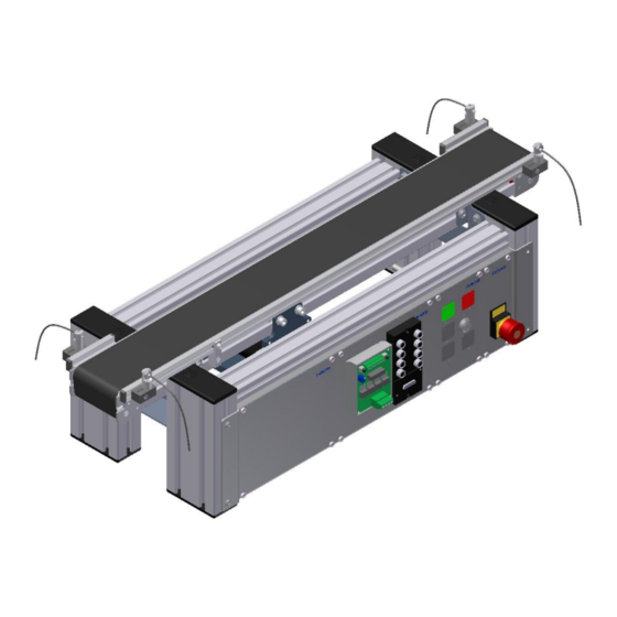
The length of the belt in the transfer line is 700 mm and the width is 80 mm. Transfer line front view Position Description Position Description Empty plate Operation panel Motor controller DC / variant Emergency stop Mini terminal © Festo Didactic GmbH & Co.KG. „ MPS-transfer system... - Page 13 ‟ different variants possible Clamping unit The system ports are realized that all additional modules can easily be connected at the transfer line. The clamping unit is designed for additional customer applications. © Festo Didactic GmbH & Co.KG. „ MPS-transfer system...
-
Page 14: Drive Variants
Position Description Position Description AC-motor variant DC motor variant The AC and DC motor variants are already implemented; other drives are for optional disposal. © Festo Didactic GmbH & Co.KG. „ MPS-transfer system... - Page 15 Connection panel with AS-i ASI Module (56419) interface Drive controller DC 4Q M-MZS-4-30 DC-Motor Voltage: 24 VDC Current: 1,5 A Duty cycle motor: 100 % ED Nominal rotation: 75 U/Min © Festo Didactic GmbH & Co.KG. „ MPS-transfer system...
- Page 16 Current limit: 2 A Time of limiting max. 50 ms Frequency of operation 1 / sec. DC-Motor Voltage: 24 VDC Current: 1,5 A Duty cycle motor: 100 % ED Nominal rotation: 75 U/Min © Festo Didactic GmbH & Co.KG. „ MPS-transfer system...
- Page 17 Current motor: 0,17 A Power: 22 W Engine speed: 2600 U/min Torque: 8,7 Ncm Gear box: 1:35 Frequency converter MM420 Build up in A4 casing with Profibus interface and operation panel © Festo Didactic GmbH & Co.KG. „ MPS-transfer system...
-
Page 18: Extension Of Transfer Line With Operation Panel
Introduction 1.2.2 Extension of transfer line with operation panel Pos. Description Variant without operation panel Variant with operation panel The functions of the operation panel are described in the respective chapter. © Festo Didactic GmbH & Co.KG. „ MPS-transfer system... - Page 19 Plug Sub-D 15 pins (2x available) SYS-link plug 24 pins (2x available) Clamp unit (1x available, parallel wired to Pos. 4) Plug Sub-D 15 pins (1x available, parallel to Pos. 3) © Festo Didactic GmbH & Co.KG. „ MPS-transfer system...
-
Page 20: Extension Of Transfer Line With Sensor Set Mt
Assemble maximum 3 sensor sets. Sensor set MT Description Ordernumber Fibre-optic cable SOEZ-LLK-SE-2,0-M4 165360 Fibre-optic unit SOEG-L-Q30-NA-S-2L 165327 Plug socket with cable SIM-M8-4WD-2,5-PU 158962 Angle for fibre-optic unit Sensor bracket M4 Sensor bracket 12 mm © Festo Didactic GmbH & Co.KG. „ MPS-transfer system... - Page 21 All work pieces should be detected reliably. Documents Data sheets Fibre optic device SOEG (165327) and fibre optic cable SOEZ-(165360) Operating instructions Fibre optic device (369684) and fibre optic cable diffuse (369682) © Festo Didactic GmbH & Co.KG. „ MPS-transfer system...
-
Page 22: Extension Of Transfer Line With Function Modules Mw
An exception is the module RFID which can only be triggered via profibus and the module camera/inspection which is triggered via Ethernet and I/O. Further details you can find in the module specific documentation. © Festo Didactic GmbH & Co.KG. „ MPS-transfer system... - Page 23 Sorting Sorting gate module electrical with C93217 is carried out using a sorting gate, which is Profibus DP operated by an electrical solenoid. © Festo Didactic GmbH & Co.KG. „ MPS-transfer system...
- Page 24 Therefore 3 light barriers are C93231 Measure module digital with ASi arranged one above the other. According the signals, the height can dedicated and C93232 Measure module digital with processed. Profibus DP © Festo Didactic GmbH & Co.KG. „ MPS-transfer system...
-
Page 25: Extension Of Transfer Line With Function Modules Mp
For each transfer line it is possible to use max. 1 module. Standardized all modules are triggered via I/O. Furthermore it is possible to trigger the modules via profibus or AS-Interface. It is not possible to use MW modules with the pallet system. © Festo Didactic GmbH & Co.KG. „ MPS-transfer system... - Page 26 Dependent from different criteria, the work pieces are sorted out. Module The module assembles or disassembles work pieces. The assembly work cartesian is done by a 3 axis handling. 3-axis handling © Festo Didactic GmbH & Co.KG. „ MPS-transfer system...
-
Page 27: Controller Options
Standardized interfaces, A4 mounting frames, the integrated 19“ mounting frame and a wide range of different controller components realize a new benchmark in education. Controller variants Festo IPC Siemens S7 Mitsubishi Rockwell Automation Siemens controller in A4 mounting frame © Festo Didactic GmbH & Co.KG. „ MPS-transfer system... - Page 28 With the training controller FC100 controller programming is getting a child´s FC100 play Programming and controlling with controller and networking with the components from the brand leaders Festo, Siemens, Rockwell or Mitsubishi © Festo Didactic GmbH & Co.KG. „ MPS-transfer system...
-
Page 29: Net Work Possibilities
/ inspection which is not extensible. Net working with AS-Interface CAN Bus Profibus DP Ethernet TCP-IP Profinet IO Profinet CBA ASIsafe PROFIsafe Net work possibilities © Festo Didactic GmbH & Co.KG. „ MPS-transfer system... -
Page 30: Profibus Adresses Module
The Learnline series of laboratory furniture provides the perfect mounting and frame for the MPS® transfer systems. Laboratory furniture with transfer line © Festo Didactic GmbH & Co.KG. „ MPS-transfer system... -
Page 31: Combination Of Transfer Line With A Working Place And Mps Stations
Combining several transfer lines a wide range of layouts can be realized. Without additional components it is possible to combine transfer lines with MPS stations of the modular productions system from Festo Didactic. combination with MPS-stations © Festo Didactic GmbH & Co.KG. „ MPS-transfer system... -
Page 32: Combination Multi Transfer Lines
Without additional modules transfer lines also can arranged „around“. With only 4 transfer lines it is possible to create a circulation system. For operation without workpiece carrier, a redirection at the corners is necessary! Combination with multi transfer lines © Festo Didactic GmbH & Co.KG. „ MPS-transfer system... -
Page 33: Work Pieces And Workpiece Carriers
A workpiece set consists of 4 cylinders each. Work pieces The workpiece „RFID“ consists of a cylindrical basic body with 40mm ø and 25mm height. A workpiece set consist of 12 cylinders. Workpiece RFID © Festo Didactic GmbH & Co.KG. „ MPS-transfer system... -
Page 34: Transportation Variants
The work piece is transported on a work piece carrier, which lies on the belt. For this way of transportation a stopper for exact position is necessary. For module family MP. Variant 2: Workpiece on workpiece carrier © Festo Didactic GmbH & Co.KG. „ MPS-transfer system... -
Page 35: Workpiece Carrier Variants
The second variant is to equip the carrier with a RFID chip ‟ for this system a RFID reading system is necessary. © Festo Didactic GmbH & Co.KG. „ MPS-transfer system... - Page 36 Introduction © Festo Didactic GmbH & Co.KG. „ MPS-transfer system...
-
Page 37: General Safety Instructions
Festo Didactic accepts no liability charges for possible damages to any trainee of the training company and/or further third parties, which might occur during use/operation of the installation, if it is not part of a real training situation;... -
Page 38: Dangers Due To Electric Current
Do not uncouple any tubes under air pressure supply. Exception: Fault finding. In this case, keep on holding the end of the tube. Do not exceed the permitted operating pressure. See data sheets. © Festo Didactic GmbH & Co.KG. „ MPS-transfer system... -
Page 39: Maintenance " Servicing " Malfunction Removal
Special care should be taken regarding safety aspects. 2.3.3 Outside training operations Activities in the areas of maintenance, service and repair are to be carried out by only persons with appropriate technical qualifications. © Festo Didactic GmbH & Co.KG. „ MPS-transfer system... -
Page 40: Safety Symbols
Failure to pay attention to this symbol may result in damages to the machine or to its surroundings. This symbol indicates operational tips and especially useful directions. INFORMATION This symbol assists you to make optimal use of all of your machine’s functions. © Festo Didactic GmbH & Co.KG. „ MPS-transfer system... -
Page 41: Start-Up
The stations are not to be picked up by or even under the mounted feet ‟ increased risk of becoming trapped or contused. © Festo Didactic GmbH & Co.KG. „ MPS-transfer system... -
Page 42: Set-Up
It is possible to put the transfer lines on every horizontal underground. It is not necessary to fix the transfer line to the underground. If the operation is done with several transfer lines it is also not necessary to fix the transfer lines together. © Festo Didactic GmbH & Co.KG. „ MPS-transfer system... -
Page 43: Assembly Of Modules
With lens-head screws M5x8 the assembly angles of the module are connected with the cross profiles ‟ don’t tie up the screws. If all screws are inserted, align the module and tie up all screws. © Festo Didactic GmbH & Co.KG. „ MPS-transfer system... -
Page 44: Pneumatical Connection Of Modules
The tube (nominal size 4) is put in the QS-plug. Install module pneumatically If there are more modules to install, connect each module with the pneumatic distributor on the transfer line. © Festo Didactic GmbH & Co.KG. „ MPS-transfer system... -
Page 45: Electrical Connection Of Modules
Cable with Sub-D connector Mini-Terminal (378355) Plugs for sensors and actuators of the modules Plug for module if a operation panel is used Plug for a module if a module distributor is used © Festo Didactic GmbH & Co.KG. „ MPS-transfer system... - Page 46 Cable with Sub-D connector Mini-Terminal (378355) Plugs for sensors and actuators of the modules Plug for module if a operation panel is used Plug for a module if a module distributor is used © Festo Didactic GmbH & Co.KG. „ MPS-transfer system...
- Page 47 PLC with AS-I card Because a AS-I filter is integrated in the Edu Trainer there is no AS-I powers supply unit necessary. Connect the black cable to 24 V for power supply. © Festo Didactic GmbH & Co.KG. „ MPS-transfer system...
- Page 48 Profibus cable to other participants or to the controller / T-connectors are necessary Plugs for sensors and actors of modules PLC ‟ for example Siemens S7 with Profibus Power supply 24V © Festo Didactic GmbH & Co.KG. „ MPS-transfer system...
-
Page 49: Connection From Modules With Operation Panel
Start up 3.2.5 Connection from modules with operation panel The electrical connection is done like shown in the graphic Connect module with Sub-D © Festo Didactic GmbH & Co.KG. „ MPS-transfer system... - Page 50 The 15 pin Sub-D plugs are exclusive for the connection of modules. It is a danger of confusion with plugs from Festo Didactic which are uses for analog signals! © Festo Didactic GmbH & Co.KG. „ MPS-transfer system...
- Page 51 If a module distributor with 37 pol. Sub-D is implemented, the connections are done like shown in the following drawing. Connect modules at operation panel and modul distributor with 37 pol. SUP-D © Festo Didactic GmbH & Co.KG. „ MPS-transfer system...
- Page 52 The 15 pin Sub-D plugs are exclusive for the connection of modules. It is a danger of confusion with plugs from Festo Didactic which are uses for analog signals! © Festo Didactic GmbH & Co.KG. „ MPS-transfer system...
- Page 53 Syslink for conveyor module (occupied Bit 4-7) and operation panel (occupied Bit 0-3) / possible to connect to a controller (8I/O) Syslink for Module Pos 1 and 2 ‟ possible to connect to a controller (8I/O) © Festo Didactic GmbH & Co.KG. „ MPS-transfer system...
-
Page 54: Connection From Modules Without Operation Panel
Start up 3.2.6 Connection from modules without operation panel The electrical connection is done like shown in the graphic Connect module with Sub-D © Festo Didactic GmbH & Co.KG. „ MPS-transfer system... - Page 55 The 15 pin Sub-D plugs are exclusive for the connection of modules. It is a danger of confusion with plugs from Festo Didactic which are uses for analog signals! © Festo Didactic GmbH & Co.KG. „ MPS-transfer system...
- Page 56 Connector for additional module / wired to SYSlink Pos.6 / occupied Bit 4-7 Syslink for Module Pos 1 and 2 ‟ possible to connect to a controller (8I/O) Syslink for Module Pos 3 and 4 ‟ possible to connect to a controller (8I/O) © Festo Didactic GmbH & Co.KG. „ MPS-transfer system...
- Page 57 Start up The electrical connection is done like shown in the graphic. Connect module to module distributor with 37 pol Sub-D © Festo Didactic GmbH & Co.KG. „ MPS-transfer system...
- Page 58 The 15 pin Sub-D plugs are exclusive for the connection of modules. It is a danger of confusion with plugs from Festo Didactic which are uses for analog signals! © Festo Didactic GmbH & Co.KG. „ MPS-transfer system...
- Page 59 X4 - connector for the conveyor module X5 ‟ connector for a additional module X6 ‟ connector for a additional module X7 ‟ connector for a additional module X8 ‟ connector for a additional module © Festo Didactic GmbH & Co.KG. „ MPS-transfer system...
-
Page 60: Commissioning
The station must be provided with electrical voltage now. The transfer line is provided with a voltage of 24 V which has to be disposed from the customer. This can to be executed only by a trained expert. © Festo Didactic GmbH & Co.KG. „ MPS-transfer system... -
Page 61: Sys Link Interface
Output AX.4 Input EX.4 Output AX.5 Input EX.5 Output AX.6 Input EX.6 Output AX.7 Input EX.7 Power supply Power supply Power supply Power supply Power supply Power supply Power supply Power supply © Festo Didactic GmbH & Co.KG. „ MPS-transfer system... -
Page 62: Pol Sub-D Plug (X1) At Module Distributor
PLC Out / Ao.2 / X7:6 PLC Out / Ao.6 / X8:6 PLC Out / Ao.1 / X7:4 PLC Out / Ao.7 / X8:8 PLC Out / Ao.0 / X7:2 Power supply Power supply © Festo Didactic GmbH & Co.KG. „ MPS-transfer system... -
Page 63: Pol Sub-D Socket (X2) At Module Distributor
PLC IN / Eo.2 / X7:5 PLC IN / Eo.6 / X8:5 PLC IN / Eo.1 / X7:3 PLC IN / Eo.7 / X8:7 PLC IN / Eo.0 / X7:1 Power supply Power supply © Festo Didactic GmbH & Co.KG. „ MPS-transfer system... -
Page 64: Prepare Electrical Connections
24 V power supply Connector module 4 16 I/O Connector module 3 Connector module 1 Operation panel Connector module 2 Connector module 5 Light barrier 1-3 Connector module 6 Pluggable connector motor © Festo Didactic GmbH & Co.KG. „ MPS-transfer system... - Page 65 Connector module 2 Connector module 5 Light barrier 1-3 Connector module 6 Frequency converter If the modules are connected to a controller, it is necessary to take care of the right addresses. © Festo Didactic GmbH & Co.KG. „ MPS-transfer system...
-
Page 66: Prepare Motor Connections Dc-Motor
Start up 3.3.7 Prepare motor connections DC-motor System overview 4Q motor controller Power supply DC motor with operation panel Pos. Description / Function Pluggable connector motor 24 V power supply Operation panel © Festo Didactic GmbH & Co.KG. „ MPS-transfer system... - Page 67 Start up Power supply motor connector at module distributor with 37 pol. Sub-D Pos. Description / Function Pluggable connector motor 24 V power supply Module distributor with 37 pol. Sub-D Operation panel © Festo Didactic GmbH & Co.KG. „ MPS-transfer system...
- Page 68 Start up Power supply DC motor with module distributor Pos. Description / Function Pluggable connector motor 24 V power supply Module distributor © Festo Didactic GmbH & Co.KG. „ MPS-transfer system...
- Page 69 Start up Power supply DC motor at module distributor with 37 pol. Sub-D Pos. Description / Function Pluggable connector motor 24 V power supply Module distributor with 37 pol. Sub-D © Festo Didactic GmbH & Co.KG. „ MPS-transfer system...
- Page 70 Start up System overview starting current limiter Power supply DC motor with operation panel Pos. Description / Function Pluggable connector motor 24 V power supply Operation panel © Festo Didactic GmbH & Co.KG. „ MPS-transfer system...
- Page 71 Start up Power supply motor connector at module distributor with 37 pol. Sub-D Pos. Description / Function Pluggable connector motor 24 V power supply Module distributor with 37 pol. Sub-D Operation panel © Festo Didactic GmbH & Co.KG. „ MPS-transfer system...
- Page 72 Start up Power supply DC motor with module distributor Pos. Description / Function Pluggable connector motor 24 V power supply Module distributor © Festo Didactic GmbH & Co.KG. „ MPS-transfer system...
- Page 73 Start up Power supply DC motor at module distributor with 37 pol. Sub-D Pos. Description / Function Pluggable connector motor 24 V power supply Module distributor with 37 pol. Sub-D © Festo Didactic GmbH & Co.KG. „ MPS-transfer system...
-
Page 74: Prepare Motor Connections Ac-Motor
Digital input 3 Output +24V Output 0V RL1-B Output ‟ relay contact RL1-C Output ‟ relay contact DAC+ Analog output (+) DAC- Analog output (-) RS 485 connector RS 485 connector © Festo Didactic GmbH & Co.KG. „ MPS-transfer system... - Page 75 Control cable set for frequency converter Mini Terminal Operation panel Power supply 230 V Motor connection via variant 1 with 4pol. cable and plug Motor connection via variant 2 with labour plugs © Festo Didactic GmbH & Co.KG. „ MPS-transfer system...
- Page 76 Mini Terminal Operation panel Module distributor 37 pol. Sub-D Power supply 230 V Motor connection via variant 1 with 4pol. cable and plug Motor connection via variant 2 with labour plugs © Festo Didactic GmbH & Co.KG. „ MPS-transfer system...
- Page 77 Control cable set for frequency converter Mini Terminal Module distributor Power supply 230 V Motor connection via variant 1 with 4pol. cable and plug Motor connection via variant 2 with labour plugs © Festo Didactic GmbH & Co.KG. „ MPS-transfer system...
- Page 78 Control cable set for frequency converter Mini Terminal Module distributor 37 pol. Sub-D Power supply 230 V Motor connection via variant 1 with 4pol. cable and plug Motor connection via variant 2 with labour plugs © Festo Didactic GmbH & Co.KG. „ MPS-transfer system...
-
Page 79: Mini Terminal
IN2 / XS4 Output Designation Mini terminal 1 motor clockwise rotation FRBR OUT0 / XS1 motor anti clockwise rotation FRBL OUT1 / XS3 Motor slow OUT2 / XS5 Motor stop OUT3 / XS7 © Festo Didactic GmbH & Co.KG. „ MPS-transfer system... - Page 80 Start up Sub-D Mini terminal 1 IN 0 OUT 0 IN 1 OUT 1 IN 2 OUT 2 IN 3 OUT 3 24 VDC © Festo Didactic GmbH & Co.KG. „ MPS-transfer system...
-
Page 81: Drive Variant With Gear Box
2:1 or the other way 1:2. The gear wheels can be assembled in both ways ‟ it depends on the costumer, it is also possible to assemble two equal gear wheels. © Festo Didactic GmbH & Co.KG. „ MPS-transfer system... - Page 82 5. Remove gear wheels and assembly like favoured. 6. During the assembly of the motor take car for tension of the tooth belt. 7. Control all screws and assemble cover. © Festo Didactic GmbH & Co.KG. „ MPS-transfer system...
-
Page 83: Change Motor
Drive head Drive head transfer line AC motor AC motor Prepared DC-motor Pos. Description Function Axis Axis DC motor Clutch disc Clutch disc Clutch doc Clutch doc 10mm Setscrew Set screw M4x6 © Festo Didactic GmbH & Co.KG. „ MPS-transfer system... - Page 84 7. Align motor flange, the holes for the screws have to be in the same orientation. 8. Assemble screws at flange and tighten them. 9. Connect the cable like described in the manual. © Festo Didactic GmbH & Co.KG. „ MPS-transfer system...
-
Page 85: Emergency Stop System
Emergency stop at mini terminal The emergency stop (E-Stop) is connected to PIN7 (Bit .7) at the mini terminal. The clamp 1 for 24 V and the clamp 4 for the signal are occupied. © Festo Didactic GmbH & Co.KG. „ MPS-transfer system... - Page 86 Emergency-stop at Edu-Trainer The emergency stop is connected directly to the Edu-trainer. If using a Edu-trainer, it is possible to configure the digital module for shut off. Please refer to manual Edu- trainer. © Festo Didactic GmbH & Co.KG. „ MPS-transfer system...
-
Page 87: Visual Check
4. Remove all of the work-pieces from the modules and from the transfer line 5. The magazines of all modules are to be stocked up 6. Now it is possible to work with the transfer lines and modules © Festo Didactic GmbH & Co.KG. „ MPS-transfer system... - Page 88 Start up © Festo Didactic GmbH & Co.KG. „ MPS-transfer system...
-
Page 89: Operation
The stations are to be operated only from trained personnel. Operation is to ensue according to operating instructions. Uncontrolled pressing of the various switches/push-buttons of the control units is to be omitted / prevented. No work-piece carriers should to be removed from the system. © Festo Didactic GmbH & Co.KG. „ MPS-transfer system... -
Page 90: Transfer Line
Key switch Not occupied Not occupied Lamp error display Not occupied Lamp error display The table assists in operating the transfer line. All of the push-buttons and lamps are described within. © Festo Didactic GmbH & Co.KG. „ MPS-transfer system... -
Page 91: Fault Finding
Adjust the screws (pos. 2) that the end of the similar screws is parallel. The tension of the belt is not high enough. Turn the screws (pos.1) inside the redirecting head. © Festo Didactic GmbH & Co.KG. „ MPS-transfer system...
Need help?
Do you have a question about the MPS transfersystem and is the answer not in the manual?
Questions and answers