Festo CPX Series Manual
Description communication profile fhpp for the cmax axis controller
Hide thumbs
Also See for CPX Series:
- Manual (346 pages) ,
- Electronic manual (232 pages) ,
- Description (156 pages)

Related Manuals for Festo CPX Series


Summary of Contents for Festo CPX Series
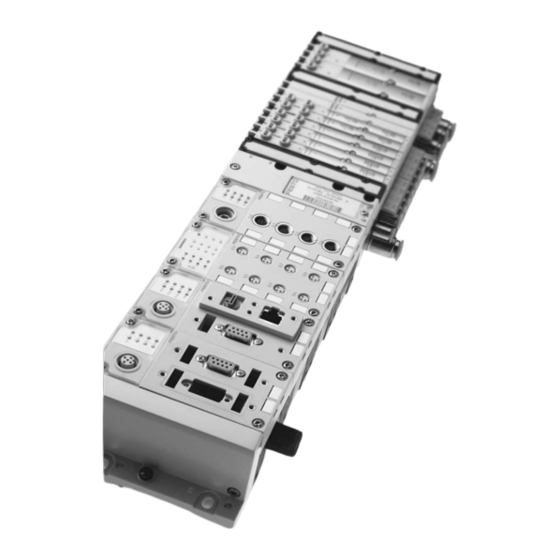
- Page 1 CPX terminal Description Communication profile FHPP for the CMAX axis controller Activation and diagnostics via CPX node Typ CPX−CMAX−C1−1 Description 559 757 en 0908NH [727 411]...
- Page 3 ....... . . 559 757 © (Festo AG & Co. KG, D 73726 Esslingen, 2009) Internet: http://www.festo.com E−mail: service_international@festo.com...
- Page 4 ® ® ® ® ® ® Interbus , DeviceNet , PROFIBUS , CC−Link , EtherNet/IP , PROFINET , Adobe ® ® Reader and TORX are registered trademarks of the respective trademark owners in certain countries. Festo P.BE−CPX−CMA X−CONTROL−EN en 0908NH...
-
Page 5: Table Of Contents
2.2.6 I/O data in parametrising mode ......2−27 Festo P.BE−CPX−CMA X−CONTROL−EN en 0908NH... - Page 6 ....... . . 3−70 3.4.2 Continuous setpoint specification (tracking mode) ... . . 3−73 Festo P.BE−CPX−CMA X−CONTROL−EN en 0908NH...
- Page 7 ..........5−52 Festo P.BE−CPX−CMA X−CONTROL−EN en 0908NH...
- Page 8 ....... . 6−15 6.3.4 Festo Parameter Channel FPC (function 1) ....6−18 Notes on commissioning and service .
- Page 9 B.8.4 Behaviour of standstill control ......B−43 Festo P.BE−CPX−CMA X−CONTROL−EN en 0908NH...
- Page 10 ............D−1 VIII Festo P.BE−CPX−CMA X−CONTROL−EN en 0908NH...
- Page 11 This description contains the communication profile for the axis controller type CPX−CMAX−C1−1. The profile is based on the Festo Handling and Positioning Profile (FHPP). This provides you with supplementary information about con trolling, diagnosing and parameterising the axis controller via the fieldbus.
- Page 12 Warning Errors in the parameterisation can cause personal injuries and damage to property. Enable the controller only if the axis system has been cor rectly installed and parameterised. Festo P.BE−CPX−CMA X−CONTROL−EN en 0908NH...
- Page 13 Service Please consult your local Festo Service or write to the follow ing e−mail address if you have any technical problems: service_international@festo.com Festo P.BE−CPX−CMA X−CONTROL−EN en 0908NH...
- Page 14 ... means that failure to observe this instruction may result in material damage. The following pictogram marks passages in the text which describe activities with electrostatically sensitive devices: Electrostatically sensitive devices: Inappropriate handling can result in damage to components. Festo P.BE−CPX−CMA X−CONTROL−EN en 0908NH...
- Page 15 Recommendations, tips and references to other sources of information. Accessories: Information about necessary or useful accessories for the Festo product. Environment: Information on the environmentally friendly use of Festo products. Text designations Bullet points indicate activities that may be carried out in · any order.
- Page 16 This description refers to the following versions: Axis controller CPX−CMAX−C1−1 starting from software version V 1.0 This description contains special information about the con trol, programming and diagnosis of a CMAX with the used CPX nodes. Festo P.BE−CPX−CMAX−CONTROL−EN en 0908NH...
- Page 17 Help for Festo Configuration Configuration and commissioning of the CMAX posi Tool with CMAX plug−in tioning module with the FCT è www.festo.com è Downloads è Download Area: Software, drivers and firmware è Enter string: CMAX Operating Operating instructions for the components used.
- Page 18 (FCT) device types. The special requirements of a device type are supported with the necessary descriptions and dialogues by means of plug−ins. Festo Handling and Fieldbus data profile for Festo position controllers. Positioning Profile (FHPP) Festo P.BE−CPX−CMA X−CONTROL−EN en 0908NH...
- Page 19 Control mode where a defined position is approached under electronic con trol and is kept. Pressure/force control Control mode for which a defined force is built up via pressure control. In the following, the term force control" will be used. XVII Festo P.BE−CPX−CMA X−CONTROL−EN en 0908NH...
- Page 20 Software end position, pos. (upper): max. limit position in the positive direction (increasing actual values). Software end position, neg. (lower): max. limit position in the negative direction (decreasing actual values). Tab. 0/2: Terms and abbreviations XVIII Festo P.BE−CPX−CMA X−CONTROL−EN en 0908NH...
-
Page 21: Cpx Terminal Configuration And Fhpp Overview
CPX terminal configuration and FHPP overview Chapter 1 1−1 Festo P.BE−CPX−CMA X−CONTROL−EN en 0908NH... - Page 22 ..... . 1−7 Commissioning instructions via the CPX node (fieldbus) ....1−8 1−2 Festo P.BE−CPX−CMA X−CONTROL−EN en 0908NH...
-
Page 23: Planning Aspects When Parametrising The Cmax
Revisions version (Rev...), see name plate. Older revisions are not suitable for use with the CMAX and can lead to unpredictable behaviour. Tab. 1/1: Instructions/special features/references for CPX nodes General parametrisation instructions are provided in the description for the used CPX node. 1−3 Festo P.BE−CPX−CMA X−CONTROL−EN en 0908NH... -
Page 24: Cmax Parameters And Cpx Node Parameters
CMAX. The internal CMAX parameters can be changed with the fol lowing functions: Festo Configuration Tool with CMAX plug−in Cyclical fieldbus communication with the control and status data of the FHPP (parametrising mode). See sections 2.2.6 and 6.2. -
Page 25: Data Format
7 6 5 4 3 2 1 0 7 6 5 4 3 2 1 0 7 6 5 4 3 2 1 0 7 6 5 4 3 2 1 0 0 0 0 0 0 0 0 1 0 1 0 0 0 1 0 0 0 1 0 0 0 1 0 0 0 0 1 0 0 0 1 0 1−5 Festo P.BE−CPX−CMA X−CONTROL−EN en 0908NH... - Page 26 After changing the para meter, wait for about 2 seconds until the CMAX conversion has been reliably executed. The CMAX swaps the values, both in the cyclical (I/O data) as well as acyclical data (parameters). 1−6 Festo P.BE−CPX−CMA X−CONTROL−EN en 0908NH...
-
Page 27: Cpx Parametrisation
CPX node. In this case, it is imperative that the CMAX be correctly parametrised, as during the initial start−up. See section 1.1.2. Follow the instructions for exchanging components in the CMAX system description. 1−7 Festo P.BE−CPX−CMA X−CONTROL−EN en 0908NH... -
Page 28: Commissioning Instructions Via The Cpx Node (Fieldbus)
Commissioning operations Section 3.2 tions Tab. 1/2: Information on how to commission via the CPX node Also follow the instructions in the CMAX system description. 1−8 Festo P.BE−CPX−CMA X−CONTROL−EN en 0908NH... -
Page 29: I/O Data And Sequence Control
I/O data and sequence control Chapter 2 2−1 Festo P.BE−CPX−CMA X−CONTROL−EN en 0908NH... - Page 30 ..........2−32 2.3.3 Special features depending on operating mode ....2−33 2−2 Festo P.BE−CPX−CMA X−CONTROL−EN en 0908NH...
-
Page 31: Operating Modes
(which arise from the transfer in the fieldbus and the PLC’s cycle time) having an effect. Detailed information on record select mode can be found in section 3.3. An overview of the I/O data can be found in section 2.2.3. 2−3 Festo P.BE−CPX−CMA X−CONTROL−EN en 0908NH... -
Page 32: Direct Operating Mode
Information about the commissioning functions can be found in section 3.1, and an overview of the I/O data can be found in section 2.2.5. 2−4 Festo P.BE−CPX−CMA X−CONTROL−EN en 0908NH... -
Page 33: Parametrisation
CMAX. Here, the first control byte CCON is transferred for controlling the enabling and operating mode of the CMAX. The seven other bytes are occupied by the Festo Parameter Channel (FPC). Parametrising mode can be activated in the states Drive/ controller disabled"... -
Page 34: Overview Of The Available Functions In The Operating Modes
Point−to−point force setpoint value On−the−fly setpoint switching (new job before MC) Identification Movement test Only permissible for STOP = 0 e.g. DPV1 Tab. 2/1: Available functions in the operating modes The drive functions are described in section 2−6 Festo P.BE−CPX−CMA X−CONTROL−EN en 0908NH... -
Page 35: Structure Of The Cyclical I/O Data In The Operating Modes
CCON.LOCK. This way, the PLC can ensure that the pro grammed sequence cannot be disturbed by access with the FCT. Evaluate the status bit SCON.FCT_MMI, and take the missing control access into consideration in the program sequence of the PLC. 2−7 Festo P.BE−CPX−CMA X−CONTROL−EN en 0908NH... -
Page 36: Ccon/Scon Structure
The operating mode is defined with CCON.OPM1 and OPM2 and is acknowledged in SCON.OPM1 and OPM2. How the control bits work together can be found under the sequence control description in section 3. 2−8 Festo P.BE−CPX−CMA X−CONTROL−EN en 0908NH... - Page 37 Operation mode OPM1 Operating Record select mode, see section 2.2.3 Mode Mode Direct operating mode see section 2 2 4 Direct operating mode, see section 2.2.4 Commissioning, see section 2.2.5 OPM2 Parametrising, see section 2.2.6 2−9 Festo P.BE−CPX−CMA X−CONTROL−EN en 0908NH...
- Page 38 FCT_MMI by Software = 1: Device control by software (FCT) (FCT/MMI) Display Oper Bit 7 6 Operation mode acknowledgment OPM1 ating Mode Record select mode Direct operating mode Direct operating mode Commissioning OPM2 Parametrising 2−10 Festo P.BE−CPX−CMA X−CONTROL−EN en 0908NH...
-
Page 39: Defining The Operating Mode With Ccon
(CCON.STOP = 0). Switching between record select mode and direct operating mode is additionally permitted for the status Ready", if MC (SPOS.MC = 1). The operating mode can also be switched if there is a Fault" status. 2−11 Festo P.BE−CPX−CMA X−CONTROL−EN en 0908NH... -
Page 40: I/O Data In The Record Select Operating Mode
Jog nega Jog posi Start Start value tive tive homing position ing task Record Byte 3: Record number of the starting record (1 to 64) Byte 3 res. Reserved = 0 Bytes 4 to 8 2−12 Festo P.BE−CPX−CMA X−CONTROL−EN en 0908NH... - Page 41 Primary Depending on the parametrisation: Actual position or actual force according to the FHPP actual setting (PNU 523:04 or 523:08) in the set system of units (section B.1). value Bytes 5 to 8 2−13 Festo P.BE−CPX−CMA X−CONTROL−EN en 0908NH...
- Page 42 Value register of the currently addressed record. Reserved, must be set to 0. CLEAR A warning is signaled for logic 1. Reserved, must be set to 0. A warning is signaled for logic 1. 2−14 Festo P.BE−CPX−CMA X−CONTROL−EN en 0908NH...
- Page 43 When programming the handshake between CPOS.START and SPOS.ACK, the registered faults must always be taken into consideration as well, since SPOS.ACK is not set in the event of a fault. MC is set for the first time after switching on (Drive disabled" status). 2−15 Festo P.BE−CPX−CMA X−CONTROL−EN en 0908NH...
- Page 44 Switching to next record: Position set sequencing Z Record Chaining The RSB (record status byte) is transferred as byte 4 in record select mode. All bits are reset at the start and are updated dynamically. 2−16 Festo P.BE−CPX−CMA X−CONTROL−EN en 0908NH...
-
Page 45: I/O Data In Direct Operating Mode
Setpoint value of the position or force in the set system of units (section B.1). The setpoint value is transferred to CPOS.START with a positive edge. setpoint During tracking mode, the setpoint position is transferred continuously after the start until Bytes tracking mode is ended. 5 to 8 2−17 Festo P.BE−CPX−CMA X−CONTROL−EN en 0908NH... - Page 46 FHPP setting (PNU 523). value Bytes 5 to 8 The status bit only changes when the job is transferred (starting edge). All other status bits in the SDIR and RSB are updated cyclically. 2−18 Festo P.BE−CPX−CMA X−CONTROL−EN en 0908NH...
- Page 47 A fault is signaled for logic 1. Reserved, must be set to 0. CLEAR A warning is signaled for logic 1. Reserved, must be set to 0. A warning is signaled for logic 1. 2−19 Festo P.BE−CPX−CMA X−CONTROL−EN en 0908NH...
- Page 48 See section 3.1.4. SPOS.MC is only set when the job is completed according to the quality class. In the event of a fast stop, the standstill monitoring is deactivated. 2−20 Festo P.BE−CPX−CMA X−CONTROL−EN en 0908NH...
- Page 49 When programming the handshake between CPOS.START and SPOS.ACK, the registered faults must always be taken into consideration as well, since SPOS.ACK might not be set in the event of a fault. MC is set for the first time after switching on (Drive disabled" status). 2−21 Festo P.BE−CPX−CMA X−CONTROL−EN en 0908NH...
- Page 50 Reserved (= 0). The SDIR status byte is the acknowledgement of positioning mode in direct mode. All bits except for B0 (ABS) and B6 (FAST) are reset at the START and then updated dynamically. 2−22 Festo P.BE−CPX−CMA X−CONTROL−EN en 0908NH...
-
Page 51: I/O Data In Commissioning Mode
Only for Identification" commissioning operation: Current workpiece mass in the set system of Bytes units (see section B.1). 5 to 8 A zero (0=) must be transferred in setpoint value bytes which aren’t used. 2−23 Festo P.BE−CPX−CMA X−CONTROL−EN en 0908NH... - Page 52 Primary Depending on the parametrisation: Actual position or actual force according to the FHPP set actual ting (PNU 523:04 or 523:08) in the set system of units (section B.1). value Bytes 5 to 8 2−24 Festo P.BE−CPX−CMA X−CONTROL−EN en 0908NH...
- Page 53 (teach target in parameter 1, see section 3.2.7). Reserved, must be set to 0. CLEAR A warning is signaled for logic 1. Reserved, must be set to 0. A warning is signaled for logic 1. 2−25 Festo P.BE−CPX−CMA X−CONTROL−EN en 0908NH...
- Page 54 When programming the handshake between CPOS.START and SPOS.ACK, the registered faults must always be taken into consideration as well, since SPOS.ACK might not be set in the event of a fault. MC is set for the first time after switching on (Drive disabled" status). 2−26 Festo P.BE−CPX−CMA X−CONTROL−EN en 0908NH...
-
Page 55: I/O Data In Parametrising Mode
Parameter number of the parameter to be transferred 12 to 15ReqID Job identifier, e.g. reading, writing, see section 6.1.1 Param. Value of the parameter to be transferred value (32−bit number) Bytes 5 to 8 2−27 Festo P.BE−CPX−CMA X−CONTROL−EN en 0908NH... - Page 56 Bytes 3+4 0...11 Parameter number of the parameter to be transferred 12 to 15 ResID Reply identifier, see section 6.1.1 Param. Value of the parameter to be transferred value (32−bit number) Bytes 5 to 8 2−28 Festo P.BE−CPX−CMA X−CONTROL−EN en 0908NH...
-
Page 57: Fhpp Finite State Machine
Reaction to faults switched on Controller Fault disabled Controller enabled (stop) Jog positive TA10 Homing is being Ready carried out TA11 Jog negative TA12 Positioning task active Operation enabled Fig. 2/1: Finite state machine 2−29 Festo P.BE−CPX−CMA X−CONTROL−EN en 0908NH... - Page 58 Transitions T4, T6 and T7* are executed from every sub−state SAx and automatically have a higher priority than any transi tion TAx. Reaction to faults T7 (Fault recognised") has the highest priority (and is marked with an asterisk *"). 2−30 Festo P.BE−CPX−CMA X−CONTROL−EN en 0908NH...
-
Page 59: Establish Ready Status
CCON = xxx0.Pxx1 Reset fault" = 0 → 1 Fault still exists. CCON = xxx0.Pxx1 Key: P = positive edge, N = negative edge, x = any Tab. 2/3: Establish transitions to ready status 2−31 Festo P.BE−CPX−CMA X−CONTROL−EN en 0908NH... -
Page 60: Positioning
Jog negative = 1 → 0 TA12 CPOS = 00xN.xxx0 Key: P = positive edge, N = negative edge, x = any TA3, TA4 and TA6 are reserved for future extensions. Tab. 2/4: Positioning transitions 2−32 Festo P.BE−CPX−CMA X−CONTROL−EN en 0908NH... -
Page 61: Special Features Depending On Operating Mode
Parametrising mode is not a positioning mode, but is only meant for transfer ring parameters. Transition T3 is not permissible. The drive, then, cannot switch to the S4 status. Tab. 2/5: Special features depending on the operating mode 2−33 Festo P.BE−CPX−CMA X−CONTROL−EN en 0908NH... - Page 62 2. I/O data and sequence control 2−34 Festo P.BE−CPX−CMA X−CONTROL−EN en 0908NH...
-
Page 63: Drive Functions
Drive functions Chapter 3 3−1 Festo P.BE−CPX−CMA X−CONTROL−EN en 0908NH... - Page 64 ....... . . 3−70 3.4.2 Continuous setpoint specification (tracking mode) ... . . 3−73 3−2 Festo P.BE−CPX−CMA X−CONTROL−EN en 0908NH...
-
Page 65: General Functional Description
Otherwise, the task is executed with the default values of the free profile and a warning message is output. Properties: The mass can be set separately for every task. Stop behaviour: Braking ramp (if possible), otherwise setpoint position = actual position. 3−3 Festo P.BE−CPX−CMA X−CONTROL−EN en 0908NH... - Page 66 The following generally applies for position control: Setpoint values are filtered (low−pass) to smoothen" jump−like changes. Following error monitoring (signal, if following error is greater than the monitoring window). Monitoring of software end positions (end position limita tion and warning). 3−4 Festo P.BE−CPX−CMA X−CONTROL−EN en 0908NH...
-
Page 67: Force Control
Stop behaviour: Setpoint position is identical to the actual position. Force ramp (modification speed) can be set. The force signaled as the actual force does not include gravity as long as the workpiece mass was given correctly in the positioning task. 3−5 Festo P.BE−CPX−CMA X−CONTROL−EN en 0908NH... - Page 68 V , and then switches to posi feed tioning mode and moves in the direction of the target force until the counteracting force increases and the con troller switches back to force control. 3−6 Festo P.BE−CPX−CMA X−CONTROL−EN en 0908NH...
- Page 69 Force control outside the software end positions is not permitted and will lead to a fault. With force control, it might be necessary to optimize the control factors more often than with position control. 3−7 Festo P.BE−CPX−CMA X−CONTROL−EN en 0908NH...
- Page 70 The stroke is limited for force control with stroke monitoring, e.g. when the workpiece being approached is not present. Speed monitoring Speed monitoring limits the speed during force control. This can prevent the drive from hitting a stop at excessive speed. 3−8 Festo P.BE−CPX−CMA X−CONTROL−EN en 0908NH...
- Page 71 I.e., the axis only moves with force control, and only limit monitoring is active. If limit monitoring is also deacti vated, the axis could crash into the end position without braking. 3−9 Festo P.BE−CPX−CMA X−CONTROL−EN en 0908NH...
-
Page 72: Standstill Control
For this reason, the standstill force can also vary in the range of the static friction. The force which is displayed at standstill therefore varies from stroke to stroke. 3−10 Festo P.BE−CPX−CMA X−CONTROL−EN en 0908NH... -
Page 73: Quality Classes
The task is completed as soon as the drive is within the tolerance. Tab. 3/1: Quality classes MC (Motion Complete, SPOS.MC) is only output when the record or task is completed according to the quality class. See section 3.1.6. 3−11 Festo P.BE−CPX−CMA X−CONTROL−EN en 0908NH... -
Page 74: Handling The Clamping Unit Or Brake
(see also CMAX system description): Pin 2: 0 V = clamping unit/brake closed Pin 2: 24 V = clamping unit/brake open. 3−12 Festo P.BE−CPX−CMA X−CONTROL−EN en 0908NH... - Page 75 (except if the controller is activated at the same time. See below). The brake then becomes active directly, even if the drive is still moving or a force has built up. Make sure that the clamping unit/brake allows this · operating state. 3−13 Festo P.BE−CPX−CMA X−CONTROL−EN en 0908NH...
- Page 76 The controller takes the workpiece mass of the last task into account. If the mass specification is incorrect (e.g. workpiece mass has changed), when the clamping unit/ brake is released, there could be compensational move ment. 3−14 Festo P.BE−CPX−CMA X−CONTROL−EN en 0908NH...
- Page 77 An overview of different cases for setting and releasing the brake is shown in Tab. 3/3. An overview of different cases for for activating and deactivat ing the controller is shown in Tab. 3/4. 3−15 Festo P.BE−CPX−CMA X−CONTROL−EN en 0908NH...
- Page 78 3. Force control with 0 force Brake is open 4. Position control with Disable controller Set = Actual (SCON.ENABLED = 0) 5. SCON.ENABLED = 1 Tab. 3/4: Behaviour for activating and deactivating the controller 3−16 Festo P.BE−CPX−CMA X−CONTROL−EN en 0908NH...
-
Page 79: Motion Complete (Mc)
MC condition possibly being met already at the beginning of the task. Here, the criteria for the MC condi tion can be influenced by the monitoring time, tolerance, and other parameters. 3−17 Festo P.BE−CPX−CMA X−CONTROL−EN en 0908NH... - Page 80 MC occurs. It is possible that the toler ance could be exited again. Due to the fast stop, the positioning time is shortened accord ingly (= time to MC). This is suitable for positions which do not require high precision. 3−18 Festo P.BE−CPX−CMA X−CONTROL−EN en 0908NH...
- Page 81 Fig. 3/4: Motion Complete (position control) Information regarding monitoring time in Fig. 3/4: Setting with PNU 1154, default = 30 ms. Setting with FCT only in expert mode under controller data, position control, monitoring time. 3−19 Festo P.BE−CPX−CMA X−CONTROL−EN en 0908NH...
-
Page 82: Mov, Dev And Still
3.1.7 Dynamically updated controller status bits MOV, DEV and STILL The status byte SPOS delivers three dynamically updated controller status bits. Description SPOS.MOV Axis is moving SPOS.DEV Following error / outside of tolerance SPOS.STILL Standstill warning Tab. 3/6: Controller status bits 3−20 Festo P.BE−CPX−CMA X−CONTROL−EN en 0908NH... - Page 83 Switch−off time T Fig. 3/5: Movement monitoring Overview of parameters involved Parameters involved Description Speed tolerance (fixed: ±4 mm/s or 0.16 in/s) Switch−off time T (fixed: 30 ms) Tab. 3/7: Parameters involved in movement monitoring 3−21 Festo P.BE−CPX−CMA X−CONTROL−EN en 0908NH...
- Page 84 Reference setpoint value Actual value Position tolerance Following error toler ance Control faults Motion Complete (SPOS.MC, B2) Deviation (SPOS.DEV, B5) Following error Outside of position ing tolerance Fig. 3/6: Following error or tolerance monitoring 3−22 Festo P.BE−CPX−CMA X−CONTROL−EN en 0908NH...
- Page 85 Force deviation 301:03 Following error tolerance (fixed: 5 N or 1.12 lbf ) Force tolerance 411:xx or 552 No parameter defined, but available in trace Tab. 3/8: Involved following error or tolerance monitoring parameters 3−23 Festo P.BE−CPX−CMA X−CONTROL−EN en 0908NH...
- Page 86 Here, no warning is entered in the diagnostic memory. The warning bit is reset when the next positioning task is started. SPOS.STILL is reset when the controller is disabled. 3−24 Festo P.BE−CPX−CMA X−CONTROL−EN en 0908NH...
- Page 87 Standstill tolerance Speed tolerance Standstill monitoring active Motion Complete (SPOS.MC, B2) Standstill error aJ aA (SPOS.STILL) Position condition met: Standstill tolerance exited Speed condition met: Drive moved for 30 ms. Fig. 3/7: Standstill monitoring 3−25 Festo P.BE−CPX−CMA X−CONTROL−EN en 0908NH...
- Page 88 545) Monitoring time 1132:04 Start (FHPP) SPOS.MC = positive edge: Motion Complete Acknowledgement SPOS.STILL = 1: The drive has moved outside the standstill tolerance win (FHPP) Tab. 3/10: Parameters involved in standstill monitoring 3−26 Festo P.BE−CPX−CMA X−CONTROL−EN en 0908NH...
-
Page 89: Limitation Of Setpoint Values
Limits" tab in expert mode. If dynamic identification is not carried out, the maximum per mitted values for acceleration must be determined by the user. By using these determined limits as setpoint values, overshoot−free positioning is guaranteed. 3−27 Festo P.BE−CPX−CMA X−CONTROL−EN en 0908NH... - Page 90 If position control was active, the last setpoint value is always 0 N. The starting and target positions are also valid, but are not displayed by the FCT. The respective actual position is used here. 3−28 Festo P.BE−CPX−CMA X−CONTROL−EN en 0908NH...
- Page 91 The maximum acceleration is determined from identification data and depends on the mass, start and target position. Deceleration Accel. That is the deceleration setpoint desired by the user. setpoint value Units index 3−29 Festo P.BE−CPX−CMA X−CONTROL−EN en 0908NH...
- Page 92 Force ramp Force The maximum force ramp determined by the controller. maximum ramp value Starting force Force For force control only: Starting force (last setpoint value) Units index Tab. 3/11: Limiting values 3−30 Festo P.BE−CPX−CMA X−CONTROL−EN en 0908NH...
- Page 93 The user has no way of controlling the read−out. If the data from the second record are to be determined, this must be carried out individually or with a correspondingly long pause. 3−31 Festo P.BE−CPX−CMA X−CONTROL−EN en 0908NH...
-
Page 94: Commissioning Operations
CMAX in the event of faults E01 and E08. If a movement test is to be carried out at a later time (e.g. after exchanging hardware), the status of the move ment test might have to be reset manually. 3−32 Festo P.BE−CPX−CMA X−CONTROL−EN en 0908NH... - Page 95 3. With the positive edge at CPOS.START, the movement test is started when commissioning operation number 2 is registered. The two parameters must have the value 0 here. When another function or positioning is started, the error E14 is signaled. 3−33 Festo P.BE−CPX−CMA X−CONTROL−EN en 0908NH...
- Page 96 = 0: Tubing connection error = 1: Tubing connection OK = 0: Movement test was not skipped = 1: Movement test was skipped 5 ... 31 Not relevant (reserved) Tab. 3/12: Status movement test 3−34 Festo P.BE−CPX−CMA X−CONTROL−EN en 0908NH...
- Page 97 2 −−> 3 ... moves in the direction of decreas ing actual values Closed Closed ... does not move +100% 1 −−> 2 4 −−> 5 ... moves in the direction of increas ing actual values 3−35 Festo P.BE−CPX−CMA X−CONTROL−EN en 0908NH...
-
Page 98: Homing
If the drive has a position measuring system with an abso lute encoder, homing is not possible. An edge at the CPOS.HOME input leads to a fault. No movement is in itiated. 3−36 Festo P.BE−CPX−CMA X−CONTROL−EN en 0908NH... -
Page 99: Homing Sequence And Parametrisation
Homing speed 1132 Start (FHPP) CPOS.HOME = positive edge: Start homing Acknowledgement SPOS.ACK = positive edge: Acknowledge Start (FHPP) SPOS.MC = 1: Movement completed SPOS.REF = 1: Drive referenced Tab. 3/13: Parameters involved in homing 3−37 Festo P.BE−CPX−CMA X−CONTROL−EN en 0908NH... - Page 100 Note If the offset is imprecisely entered, the drive could end up vibrating strongly depending on the setting of the involved parameters. Always carry out identification again after the offset has · been corrected. 3−38 Festo P.BE−CPX−CMA X−CONTROL−EN en 0908NH...
-
Page 101: Homing Run Methods
This position is saved as a reference point. Positive stop −18 Run at reference speed in positive direction to · stop. This position is saved as a reference point. Tab. 3/14: Overview of homing methods 3−39 Festo P.BE−CPX−CMA X−CONTROL−EN en 0908NH... -
Page 102: Identification And Adaptation
The CMAX signals a warning if identification should be carried out due to a change. The CMAX signals a fault if identification must be carried out due to a change. The identification status parameter (PNU 1171) contains information about the identification status. 3−40 Festo P.BE−CPX−CMA X−CONTROL−EN en 0908NH... - Page 103 It might be necessary to manually optimise these values. Carrying out identification Only for pneumatic drives with incremental position measur ing system (e.g. type DNCI−...): Homing must be carried out before the identification run. 3−41 Festo P.BE−CPX−CMA X−CONTROL−EN en 0908NH...
- Page 104 2. Dynamic identification (if configured). 3. If dynamic identification has been carried out: Determina tion of the maximum values for acceleration and deceler ation for a stroke of 90% of the effective stroke in both directions. 3−42 Festo P.BE−CPX−CMA X−CONTROL−EN en 0908NH...
- Page 105 If the mass changes considerably during operation, identification should be carried out both with and without the workpiece. If the identification run is interrupted while in progress, static or dynamic identification data determined up to that point remains active. 3−43 Festo P.BE−CPX−CMA X−CONTROL−EN en 0908NH...
- Page 106 E30 messages piling up. For this reason, one should only deactivate adapta tion if this is justified. 3−44 Festo P.BE−CPX−CMA X−CONTROL−EN en 0908NH...
- Page 107 In these cases, adaptation could be responsible. If this is your guess, deactivate adaptation and carry out identification again afterwards. If the positioning behaviour doesn’t change again afterwards, adaptation was probably the cause and should remain deacti vated. 3−45 Festo P.BE−CPX−CMA X−CONTROL−EN en 0908NH...
-
Page 108: Jog Mode
The software end position is not passed; the travel for stopping is taken into account in accordance with the set ramp. Here, too, Jog mode is only exited again after CPOS.JOGx = 0. 3−46 Festo P.BE−CPX−CMA X−CONTROL−EN en 0908NH... - Page 109 Jogging must be restarted at the end position. The drive moves at creeping speed to the hardware end positions by means of an edge( } teaching the software end positions). When the software end positions are passed, warning W35 is signaled. 3−47 Festo P.BE−CPX−CMA X−CONTROL−EN en 0908NH...
- Page 110 To avoid a timeout here, the status bit SPOS.MOV should be evaluated. If this is a logic 0 for at least 50 ms, jogging should be terminated. 3−48 Festo P.BE−CPX−CMA X−CONTROL−EN en 0908NH...
- Page 111 Depending on the parametrisation (PNU521), the default value is used for the workpiece mass. See section 5.3. Tab. 3/16: Parameters involved in jog mode The ratio of the speeds to one another is not limited. PNU 531 can be less than or equal to PNU 530. 3−49 Festo P.BE−CPX−CMA X−CONTROL−EN en 0908NH...
-
Page 112: Teaching
2. Via jog mode, the drive is put into the desired position by positioning or manually (by moving by hand in Drive disabled" state). 3. Teaching is done via the bit handshake in the control and status bytes CPOS/SPOS (Fig. 3/9). 3−50 Festo P.BE−CPX−CMA X−CONTROL−EN en 0908NH... - Page 113 Here, the position is fundamentally taught. Only absolute setpoint values are taught. During teach ing, bit RCB1.ABS = 0 is therefore set in record control byte 1 of the taught record. 3−51 Festo P.BE−CPX−CMA X−CONTROL−EN en 0908NH...
- Page 114 SPOS Function Param. 1: Primary actual value data Teach target Teach target (byte 4) Value Applies to What’s taught is 500:00 Project zero point 501:01 Negative software end position 501:02 Positive software end position 3−52 Festo P.BE−CPX−CMA X−CONTROL−EN en 0908NH...
- Page 115 The upper software end position is then automatically set to the upper hardware end posi tion by the CMAX. 3−53 Festo P.BE−CPX−CMA X−CONTROL−EN en 0908NH...
- Page 116 Commissioning: Teaching is not permissible while a commissioning operation is being executed. Tab. 3/17: Causes for error E44 during teaching The cause for E44 during teaching is shown in the diagnostic memory in accordance with Tab. 3/17. 3−54 Festo P.BE−CPX−CMA X−CONTROL−EN en 0908NH...
-
Page 117: Record Select Operating Mode (Record Select Mode)
Tab. 3/18 shows the suppor ted controller functions during record selection. Controller function is supported Point−to−point (PTP) positioning PTP force control Continuous positioning Continuous force control On−the−fly setpoint switching Tab. 3/18: Supported controller functions 3−55 Festo P.BE−CPX−CMA X−CONTROL−EN en 0908NH... - Page 118 SPOS.MOV = 1: Drive is moving Depending on parametrisation (PNU403), instead of record data in PNU 406 to 412, the default values are used from PNU 600 to 608. See section 5.3. Tab. 3/19: Record Select parameters involved 3−56 Festo P.BE−CPX−CMA X−CONTROL−EN en 0908NH...
-
Page 119: Start Of A Record
SCON.FAULT must be 0 during the entire sequence. 2 If SPOS.ACK (Acknowledge Start) = 0, the PLC can initiate execution of the record with a rising edge at CPOS.START. 3−57 Festo P.BE−CPX−CMA X−CONTROL−EN en 0908NH... - Page 120 Typical causes of error in applications: Referencing has not been carried out. Selection of an invalid record number or a record that has not been initialised. The target value lies outside the software end positions. 3−58 Festo P.BE−CPX−CMA X−CONTROL−EN en 0908NH...
- Page 121 If there is a stop or error type F1 (controlled), there is a switch to position control (set = actual, etc.). Force tasks following positioning tasks with a relative setpoint value refer to force 0. 3−59 Festo P.BE−CPX−CMA X−CONTROL−EN en 0908NH...
-
Page 122: Record Structure
Force ramp not used Force ramp The default values are used depending on PNU 403 (RPC). See Tab. 3/19. The acceleration and deceleration parameters are not used for force control. Tab. 3/20: Record parameters 3−60 Festo P.BE−CPX−CMA X−CONTROL−EN en 0908NH... -
Page 123: Conditional Record Switching / Record Chaining (Pnu 402)
Numerical value 0 to 128: Switching condition as a list, see Tab. 3/23 0 to 6 Bit 7 = 0: Record switching (bit 0 to 6) is not disabled (default) = 1: Record switching disabled Tab. 3/21: Settings for conditional record switching and record chaining 3−61 Festo P.BE−CPX−CMA X−CONTROL−EN en 0908NH... - Page 124 A record switch to a record with an automatic profile is only possible with the switch condition MC". If such a switch is set, a warning (W37) is signaled during execution and the free profile is used. 3−62 Festo P.BE−CPX−CMA X−CONTROL−EN en 0908NH...
- Page 125 Only when the axis is positioned against a spring force, for example, and the force which occurs here is more than twice the frictional forces, including the acceleration force, does the switch result in more−or− less reproducible behaviour. 3−63 Festo P.BE−CPX−CMA X−CONTROL−EN en 0908NH...
- Page 126 T1 1. Speed The time T1 is started at the beginning of positioning. The next record is switched to once the time has elapsed 2. MC can already be reached here. 3−64 Festo P.BE−CPX−CMA X−CONTROL−EN en 0908NH...
- Page 127 Note: Motion Complete is also not set to 1 for this switching condition while the record is being processed, but only when the CMAX has carried out the last chained record. 3−65 Festo P.BE−CPX−CMA X−CONTROL−EN en 0908NH...
- Page 128 SPOS.MC is set to 1 and a diagnostic message (W28/E28) is output. If the timeout time for force control is deactivated (set to 0), the drive waits indefinitely for the switching position to be reached. 3−66 Festo P.BE−CPX−CMA X−CONTROL−EN en 0908NH...
- Page 129 SPOS.MC is set to 1 and a diagnostic message (W28/E28) is output. If the timeout time for force control is deactivated (set to 0), the drive waits indefinitely for the switching position to be reached. 15 ... Reserved Tab. 3/23: Switching conditions 3−67 Festo P.BE−CPX−CMA X−CONTROL−EN en 0908NH...
-
Page 130: Direct Operating Mode (Direct Mode)
Typical causes of error in applications No referencing carried out. Target position or target force cannot be reached or are outside of the software end positions. Timeout (target position or target force are not reached). 3−68 Festo P.BE−CPX−CMA X−CONTROL−EN en 0908NH... - Page 131 PNU 600 to 608. See section 5.3. The PLC transfers a percent value in the control bytes, which is multiplied by the basic value in order to get the final setpoint value. Tab. 3/24: Parameters involved, direct mode 3−69 Festo P.BE−CPX−CMA X−CONTROL−EN en 0908NH...
-
Page 132: Start Of A Positioning Task
SCON.FAULT must be 0 during the entire sequence. 2 With the rising edge at CPOS.START, the CMAX accepts the setpoint values, starts the positioning task, sets SPOS.MC = 0 and acknowledges the starting edge with SPOS.ACK. 3−70 Festo P.BE−CPX−CMA X−CONTROL−EN en 0908NH... - Page 133 MC can occur at the same time as the rising edge at ACK. In the event of faults, the task might not be acknowledged with SPOS.ACK. For this reason, the SCON.FAULT bit must always be evaluated in addition. 3−71 Festo P.BE−CPX−CMA X−CONTROL−EN en 0908NH...
- Page 134 The sum of the tool and workpiece masses must not exceed 2000 kg. The setpoint values are limited to the software or hardware end positions or the set force limit. Tab. 3/25: Setpoint value limitation in direct mode 3−72 Festo P.BE−CPX−CMA X−CONTROL−EN en 0908NH...
-
Page 135: Continuous Setpoint Specification (Tracking Mode)
4 The setpoint tracking is ended 4 with a falling edge at CPOS.START 3. The drive is stopped with a stop ramp. 3−73 Festo P.BE−CPX−CMA X−CONTROL−EN en 0908NH... - Page 136 3. Drive functions 3−74 Festo P.BE−CPX−CMA X−CONTROL−EN en 0908NH...
-
Page 137: Faults And Diagnostics
Faults and diagnostics Chapter 4 4−1 Festo P.BE−CPX−CMA X−CONTROL−EN en 0908NH... - Page 138 ....4−48 4.5.3 Split up: Parametrising via the I/O diagnostic interface ..4−51 4−2 Festo P.BE−CPX−CMA X−CONTROL−EN en 0908NH...
-
Page 139: Overview Of Diagnostics Options
CPX module concept. FHPP diagnostics Diagnostic parameters Section 4.3 via communi via communi Diagnostic memory Section 4.3.2 cations profile The CPX diagnostics only show the fault groups of the CMAX. Tab. 4/1: Diagnostics options 4−3 Festo P.BE−CPX−CMA X−CONTROL−EN en 0908NH... -
Page 140: Faults And Warnings
(level F2), drive moves using residual energy until it comes to a standstill. The CMAX display always indicates the fault that occurred first. If additional faults occur, they are not indicated even if they are more serious. 4−4 Festo P.BE−CPX−CMA X−CONTROL−EN en 0908NH... - Page 141 Acknowledging warnings Depending on the warning, SCON.WARN = 0 as soon as the cause has been eliminated. with positive edge on CCON.START or CCON.RESET (pro vided the cause was eliminated). 4−5 Festo P.BE−CPX−CMA X−CONTROL−EN en 0908NH...
-
Page 142: Error Numbers On The Cpx Terminal
Record error [Record error] Control error [Control error] System error A [System error A] System error B [System error B] Error in valve [Error in valve] Controller error [Controller error] Measuring system error [Encoder error] 4−6 Festo P.BE−CPX−CMA X−CONTROL−EN en 0908NH... -
Page 143: Fault Level: Classification According To The Response To The Fault
Should communication with the measuring system/sensor interface fail, the reference may be lost (SPOS.REF = 0). System error FS : Serious error in firmware (No firmware, ...): It may no longer be possible to up date the I/O data. Tab. 4/2: Fault levels 4−7 Festo P.BE−CPX−CMA X−CONTROL−EN en 0908NH... -
Page 144: Reset Types: Behaviour In The Event Of Fault Acknowledgement
Tab. 4/3: Acknowledging fault messages reset types Acknowledging warnings In the event of warnings, the CMAX does not have the Fault" status, but remains Ready". Warnings are deleted in the event of CCON.RESET or CPOS.START (provided the cause was eliminated). 4−8 Festo P.BE−CPX−CMA X−CONTROL−EN en 0908NH... -
Page 145: Error Number And Warning Numbers
= no info; x = additional info, see FCT or section 4.3.3 The movement test is reset to avoid tubing errors. The CMAX has C03 status. The movement test should then be run once more. 4−9 Festo P.BE−CPX−CMA X−CONTROL−EN en 0908NH... - Page 146 = no info; x = additional info, see FCT or section 4.3.3 The movement test is reset to avoid tubing errors. The CMAX has C03 status. The movement test should then be run once more. 4−10 Festo P.BE−CPX−CMA X−CONTROL−EN en 0908NH...
- Page 147 · valve and cylinder (emergency stop) are closed. Level: fault level, see section 4.2.3 Reset: behaviour upon reset, see section 4.2.4 Info: = no info; x = additional info, see FCT or section 4.3.3 4−11 Festo P.BE−CPX−CMA X−CONTROL−EN en 0908NH...
- Page 148 Level: fault level, see section 4.2.3 Reset: behaviour upon reset, see section 4.2.4 Info: = no info; x = additional info, see FCT or section 4.3.3 Parameter 2: Byte 4 ... 8 in commissioning mode. 4−12 Festo P.BE−CPX−CMA X−CONTROL−EN en 0908NH...
- Page 149 SPOS.MC = 1 (CCON.STOP = 1). Level: fault level, see section 4.2.3 Reset: behaviour upon reset, see section 4.2.4 Info: = no info; x = additional info, see FCT or section 4.3.3 4−13 Festo P.BE−CPX−CMA X−CONTROL−EN en 0908NH...
- Page 150 Level: fault level, see section 4.2.3 Reset: behaviour upon reset, see section 4.2.4 Info: = no info; x = additional info, see FCT or section 4.3.3 4−14 Festo P.BE−CPX−CMA X−CONTROL−EN en 0908NH...
- Page 151 Level: fault level, see section 4.2.3; (can alternatively be parametrised as a warning or error) Reset: behaviour upon reset, see section 4.2.4 Info: = no info; x = additional info, see FCT or section 4.3.3 4−15 Festo P.BE−CPX−CMA X−CONTROL−EN en 0908NH...
- Page 152 = no info; x = additional info, see FCT or section 4.3.3 The drive did not reach the target tolerance on time. (MC monitoring). Record chaining is cancelled. Can, for instance, occur during positioning or jogging on a stop within the effective stroke. 4−16 Festo P.BE−CPX−CMA X−CONTROL−EN en 0908NH...
- Page 153 = no info; x = additional info, see FCT or section 4.3.3 e.g. setoff timeout, i.e. the drive did not perform the minimal stroke of 11 mm within the timeout time, or during identification. 4−17 Festo P.BE−CPX−CMA X−CONTROL−EN en 0908NH...
- Page 154 Reset: behaviour upon reset, see section 4.2.4 Info: = no info; x = additional info, see FCT or section 4.3.3 The actual position has exceeded a software end position during active closed loop position con trol. 4−18 Festo P.BE−CPX−CMA X−CONTROL−EN en 0908NH...
- Page 155 Level: fault level, see section 4.2.3; (can alternatively be parametrised as a warning or error) Reset: behaviour upon reset, see section 4.2.4 Info: = no info; x = additional info, see FCT or section 4.3.3 The actual position has exceeded a software end position during active force control. 4−19 Festo P.BE−CPX−CMA X−CONTROL−EN en 0908NH...
- Page 156 Level: fault level, see section 4.2.3; (can alternatively be parametrised as a warning or error) Reset: behaviour upon reset, see section 4.2.4 Info: = no info; x = additional info, see FCT or section 4.3.3 4−20 Festo P.BE−CPX−CMA X−CONTROL−EN en 0908NH...
- Page 157 Level: fault level, see section 4.2.3; (can alternatively be parametrised as a warning or error) Reset: behaviour upon reset, see section 4.2.4 Info: = no info; x = additional info, see FCT or section 4.3.3 4−21 Festo P.BE−CPX−CMA X−CONTROL−EN en 0908NH...
- Page 158 Level: fault level, see section 4.2.3; (can alternatively be parametrised as a warning or error) Reset: behaviour upon reset, see section 4.2.4 Info: = no info; x = additional info, see FCT or section 4.3.3 For exact cause, see diagnostic memory. 4−22 Festo P.BE−CPX−CMA X−CONTROL−EN en 0908NH...
- Page 159 Reset: behaviour upon reset, see section 4.2.4 Info: = no info; x = additional info, see FCT or section 4.3.3 For exact cause, see diagnostic memory. See I/O data in the description CMAX communication profile" 4−23 Festo P.BE−CPX−CMA X−CONTROL−EN en 0908NH...
- Page 160 Level: fault level, see section 4.2.3; (can alternatively be parametrised as a warning or error) Reset: behaviour upon reset, see section 4.2.4 Info: = no info; x = additional info, see FCT or section 4.3.3 Enable command, but no supply pressure. 4−24 Festo P.BE−CPX−CMA X−CONTROL−EN en 0908NH...
- Page 161 Level: fault level, see section 4.2.3; (can alternatively be parametrised as a warning or error) Reset: behaviour upon reset, see section 4.2.4 Info: = no info; x = additional info, see FCT or section 4.3.3 4−25 Festo P.BE−CPX−CMA X−CONTROL−EN en 0908NH...
- Page 162 Level: fault level, see section 4.2.3; (can alternatively be parametrised as a warning or error) Reset: behaviour upon reset, see section 4.2.4 Info: = no info; x = additional info, see FCT or section 4.3.3 4−26 Festo P.BE−CPX−CMA X−CONTROL−EN en 0908NH...
- Page 163 Level: fault level, see section 4.2.3; (can alternatively be parametrised as a warning or error) Reset: behaviour upon reset, see section 4.2.4 Info: = no info; x = additional info, see FCT or section 4.3.3 4−27 Festo P.BE−CPX−CMA X−CONTROL−EN en 0908NH...
- Page 164 Level: fault level, see section 4.2.3; (can alternatively be parametrised as a warning or error) Reset: behaviour upon reset, see section 4.2.4 Info: = no info; x = additional info, see FCT or section 4.3.3 4−28 Festo P.BE−CPX−CMA X−CONTROL−EN en 0908NH...
- Page 165 Level: fault level, see section 4.2.3; (can alternatively be parametrised as a warning or error) Reset: behaviour upon reset, see section 4.2.4 Info: = no info; x = additional info, see FCT or section 4.3.3 4−29 Festo P.BE−CPX−CMA X−CONTROL−EN en 0908NH...
- Page 166 Level: fault level, see section 4.2.3; (can alternatively be parametrised as a warning or error) Reset: behaviour upon reset, see section 4.2.4 Info: = no info; x = additional info, see FCT or section 4.3.3 4−30 Festo P.BE−CPX−CMA X−CONTROL−EN en 0908NH...
-
Page 167: Diagnostic Parameters
CMAX possible. It is always the fault that occurred first that is displayed. PNU 226 The PNU 226 contains the warning number the FCT is supposed to display. The warning is not shown on the CMAX display. 4−31 Festo P.BE−CPX−CMA X−CONTROL−EN en 0908NH... -
Page 168: Diagnostic Memory
When reading, the newest entry is read first (LIFO principle). Number (subindex) Diagnostic memory entry Newest (last) diagnostic message. Last but one diagnostic message. Oldest diagnostic message. Tab. 4/6: Structure of the diagnostic memory 4−32 Festo P.BE−CPX−CMA X−CONTROL−EN en 0908NH... - Page 169 Detailed information on the fault. The evaluation is complex and therefore PNU 203 suitable for a PLC program to a limited extent only. For description see section 4.3.3. Tab. 4/8: Parameters of the diagnostic memory 4−33 Festo P.BE−CPX−CMA X−CONTROL−EN en 0908NH...
- Page 170 Depending on the event, the FCT can provide detailed in formation on the respective entry with the help of the addi tional information. Fig. 4/1: Example of display of the diagnostic memory in FCT 4−34 Festo P.BE−CPX−CMA X−CONTROL−EN en 0908NH...
- Page 171 Number of unread entries. Is set to 0 when index 4 is read. With every new entry into the diagnostic memory, the value is increased by 1. Tab. 4/11: Administration of the diagnostic memory 4−35 Festo P.BE−CPX−CMA X−CONTROL−EN en 0908NH...
-
Page 172: Fault Status (Pnu 227) And Additional Information (Pnu 203)
A S Reset Level Info Details The coding is the same for PNU 203 and 227, but it only con tains the information that is useful and available for the re spective parameter. 4−36 Festo P.BE−CPX−CMA X−CONTROL−EN en 0908NH... - Page 173 Describes what the error details refer to (203/−−) see Tab. 4/13. Bit 7..0 Details Additional details on the cause of the fault (203/−−) see Tab. 4/13. Tab. 4/12: Assignment of the additional information for future faults. 4−37 Festo P.BE−CPX−CMA X−CONTROL−EN en 0908NH...
- Page 174 The upper software end position is larger than the upper hard ware end position. The lower software end position is larger than or the same as the upper software end position. 4−38 Festo P.BE−CPX−CMA X−CONTROL−EN en 0908NH...
- Page 175 Value range nn: 0 to 255 Commissioning In the event of a general fault in commissioning mode, operation the commissioning operation started last is entered. Value range nn: 0 to 255 4−39 Festo P.BE−CPX−CMA X−CONTROL−EN en 0908NH...
- Page 176 Jog mode in positive direction (JogP). Teaching Teach setpoint value in record list. Teach lower software end position. Teach upper software end position. Teach offset project zero point. Tab. 4/13: Information and details for future faults 4−40 Festo P.BE−CPX−CMA X−CONTROL−EN en 0908NH...
-
Page 177: Diagnostic Code And Additional Information With Reset Switching On And Configuration
New start of the axis performed. Additional information Info Description Byte 1 Number of resets so far Byte 2 reserved Byte 3 + 4 In case value > 0: Reset duration in milliseconds after restart of the axis 4−41 Festo P.BE−CPX−CMA X−CONTROL−EN en 0908NH... - Page 178 Start in configuration mode C03: Movement test must be carried out. Additional information Info Description Byte 1 Number of switch−on processes so far Byte 2 reserved Byte 3 + 4 Duty cycle in milliseconds 4−42 Festo P.BE−CPX−CMA X−CONTROL−EN en 0908NH...
- Page 179 Identification reset, identification data were deleted. Additional information Info Description Byte 1 = 1: Successfully carried out = 2: Execution cancelled Byte 2 reserved Byte 3 + 4 Duration of the function in 0.1 seconds 4−43 Festo P.BE−CPX−CMA X−CONTROL−EN en 0908NH...
-
Page 180: Configuration Of Diagnostic Messages And Faults
Specifi cation Record warnings Record configuration events (data reset, identification etc.) Record reset commands Record switch−on processes 4 ... 31 reserved (=: 0 !) Tab. 4/15: Configuration of the diagnostic messages diagnostic events filter 4−44 Festo P.BE−CPX−CMA X−CONTROL−EN en 0908NH... - Page 181 Often the right correct reaction depends on the application in these cases. With faults where both reactions are possible you can define the behaviour of the CMAX. 4−45 Festo P.BE−CPX−CMA X−CONTROL−EN en 0908NH...
- Page 182 9 ... 31 reserved (= 0 !) 0 = The message is treated as a fault; 1 = The message is treated as a warning Tab. 4/17: Configuration of the diagnostic messages configuration of fault messages 4−46 Festo P.BE−CPX−CMA X−CONTROL−EN en 0908NH...
-
Page 183: Diagnostics Via Standard Functions Of The Cpx Terminal
Error at input Error on analogue module/ Bit 3 is set for all errors of the CMAX. technology module Undervoltage Type of error Short circuit/overload Wire break Other error Tab. 4/18: Overview of status bits 4−47 Festo P.BE−CPX−CMA X−CONTROL−EN en 0908NH... -
Page 184: I/O Diagnostic Interface And Diagnostic Memory
(diagnostic event) [NB] = 0 ... 39 ; most current diagnostic event = 0 Tab. 4/19: Diagnostic memory data of the CMAX Instructions on diagnostics with the I/O diagnostic interface can be found in the CPX system manual. 4−48 Festo P.BE−CPX−CMA X−CONTROL−EN en 0908NH... - Page 185 5 ... 0 Description 10000001 0 ... 0 Error in I channel Error number [FN] CPX error number: 105 01101001 Following channels Always 0 for the CMAX 00000000 Tab. 4/20: Example of diagnostic memory entry 4−49 Festo P.BE−CPX−CMA X−CONTROL−EN en 0908NH...
- Page 186 Description Error number Bit 0 ... 7 : error number Values 100 ... 108: CPX error number, (see example Tab. 4/20) Note For CMAX error messages, see section 4.2.2. Tab. 4/22: Module error number 4−50 Festo P.BE−CPX−CMA X−CONTROL−EN en 0908NH...
-
Page 187: Split Up: Parametrising Via The I/O Diagnostic Interface
4828 + m*64 + 8 ... 11 Task control 4828 + m*64 + 12 ... 61 50 byte data (depending on the task). 4828 + m*64 + 62, 63 reserved m = module number Tab. 4/23: I/O diagnostic interface 4−51 Festo P.BE−CPX−CMA X−CONTROL−EN en 0908NH... - Page 188 Specifies the serial number of the module (8 digits). Structure: YMNNNNNN Y=Year, M=Month, NNNNNN = continuous number (BCD−encoded) Example: 37 12 34 56 Date = July 2003 (Year: 0 ... F = 2000 ... 2015; month: 0 ... C) 123456: continuous number 4−52 Festo P.BE−CPX−CMA X−CONTROL−EN en 0908NH...
-
Page 189: Parameter
Parameter Chapter 5 5−1 Festo P.BE−CPX−CMA X−CONTROL−EN en 0908NH... - Page 190 ..........5−93 5−2 Festo P.BE−CPX−CMA X−CONTROL−EN en 0908NH...
-
Page 191: General Parameter Structure Of The Cmax
Cylinder lengths and diameter, valve type, ... Controller data 1150 ... 1189 Amplification factors, identification, adapta tion. Commissioning data 1190 ... 1199 Actual configuration, system of measure ment, data reset ... Tab. 5/1: Parameter structure 5−3 Festo P.BE−CPX−CMA X−CONTROL−EN en 0908NH... - Page 192 Tab. 5/2: Parameter classes for the CMAX Data types Attribute / use bitarray 4−byte value whose individual bits have separate meanings. char 8−bit ASCII characters. int32 4−byte integer value with sign. Tab. 5/3: Data types for the CMAX 5−4 Festo P.BE−CPX−CMA X−CONTROL−EN en 0908NH...
-
Page 193: Access Protection
Areas that are protected are the modification of parameters and the controlling of inputs, start, stop, teaching and firm ware download. Permissible is the display of parameters, project upload, the display of actual values, setpoint values, diagnostic data. 5−5 Festo P.BE−CPX−CMA X−CONTROL−EN en 0908NH... - Page 194 The password is implemented as a string in CMAX and con sists of 8 bytes (ASCII code: 32 to 127). This permits upper and lower case letters, numerals and special characters such as dash ’−’, smaller ’< ’, at ’@’ etc. 5−6 Festo P.BE−CPX−CMA X−CONTROL−EN en 0908NH...
- Page 195 FCT, not via the PLC. Information on the password protection can be found in the CMAX FCT−PlugIn Help and in the PNU in section 5.4.2 and PNU 1192 in section 5.4.16. 5−7 Festo P.BE−CPX−CMA X−CONTROL−EN en 0908NH...
-
Page 196: Access Via Plc And Fct
SCON.FCT_MMI indicates that the drive is controlled by the FCT and that no control over the drive is possible via the I/O data. The PLC can react by switching to stop or manual oper ation. 5−8 Festo P.BE−CPX−CMA X−CONTROL−EN en 0908NH... -
Page 197: Status−Dependent And Operating Mode Dependent Lock
Each parameter also states which operating status is needed. To write a commissioning parameter commissioning mode or parametrising mode must be active, the controller must be locked (CCON.ENABLE = 0) 5−9 Festo P.BE−CPX−CMA X−CONTROL−EN en 0908NH... -
Page 198: Enable And Stop With Parametrisation
.ENABLE .STOP .ENABLE .STOP Record selection Direct mode Commissioning Parametrisation 0 / x x / 0 With commissioning parameters CCON.ENABLE = 0 must be set Tab. 5/6: Effect of the parameter transfer to CCON 5−10 Festo P.BE−CPX−CMA X−CONTROL−EN en 0908NH... -
Page 199: Default Values
In order to use values other than the default values in an indi vidual record, you only need to specify the values for the re cord parameter in this one record. 5−11 Festo P.BE−CPX−CMA X−CONTROL−EN en 0908NH... - Page 200 Record Parameter Control (RPC) Direct Mode Parameter Control (DMPC) Direct mode for position Direct Mode Parameter Control (DMPC) Direct mode for force Direct Mode Parameter Control (DMPC) Tab. 5/7: Control of the default values 5−12 Festo P.BE−CPX−CMA X−CONTROL−EN en 0908NH...
- Page 201 Bit = 0 Bit = 1 Record Position Force select mode Speed, position Force speed Acceleration Deceleration (reserved) Workpiece mass Position tolerance Force tolerance Force ramp 9 ... 29 (reserved) Tab. 5/9: Parameters used 5−13 Festo P.BE−CPX−CMA X−CONTROL−EN en 0908NH...
- Page 202 From the unloading position 4 the slide can return to the initial position 1 at full speed. Tab. 5/10: Example of default values: Steps 5−14 Festo P.BE−CPX−CMA X−CONTROL−EN en 0908NH...
- Page 203 Bit 3 Bit 5 Bit 6 Bit 8 0001 0004 0008 0020h 0040h 0100h C000 0000 7500 C000 0020 14550 C000 002D 20520 C000 0000 2000 Tab. 5/12: Example of default values: Record list 5−15 Festo P.BE−CPX−CMA X−CONTROL−EN en 0908NH...
- Page 204 205.2 mm 0.4 m/s 0.2 m/s 0.2 m/s 25.0 kg 0.5 mm 205.2 mm 20.0 mm 1.0 m/s 1.0 m/s 1.0 m/s 0.0 kg 0.5 mm Tab. 5/13: Example of default values: Movements performed 5−16 Festo P.BE−CPX−CMA X−CONTROL−EN en 0908NH...
-
Page 205: Description Of The Parameters
Password Array char Secret system password int32 System time: Qty. operating Struct int32 days System time: millisec. of the Struct int32 Name of X−axis Array char Name of Y−axis Array char see Tab. 5/15 5−17 Festo P.BE−CPX−CMAX−CONTROL−EN en 0908NH... - Page 206 Struct int32 mands Count of force commands Struct int32 Cumulated stroke length Struct int32 Cumulated stroke length fract. Struct int32 Current speed int32 Extended axis status bitarray 0 Valve output value int32 see Tab. 5/15 5−18 Festo P.BE−CPX−CMAX−CONTROL−EN en 0908NH...
- Page 207 Direct mode force parameter Array bitarray 0 control FHPP: Control/Status bits: Struct int32 SH IB CPOS.HALT support FHPP: Control/Status bits: Struct int32 SH IB CCON.BRAKE level FHPP: Setpoint/actual values Struct int32 see Tab. 5/15 5−19 Festo P.BE−CPX−CMAX−CONTROL−EN en 0908NH...
- Page 208 Default values, see section 5.4.10 Speed position mode int32 Speed force mode int32 Acceleration int32 Deceleration int32 Workpiece mass int32 NB UL Tolerance position mode int32 Tolerance force mode int32 Force ramp int32 see Tab. 5/15 5−20 Festo P.BE−CPX−CMAX−CONTROL−EN en 0908NH...
- Page 209 NB UL 1152 1 Pos. contr. filter factor int32 NB UL 1153 1 Pos. contr. timeout int32 NB UL 1154 1 Pos. contr. damping time for int32 NB UL exact stop see Tab. 5/15 5−21 Festo P.BE−CPX−CMAX−CONTROL−EN en 0908NH...
- Page 210 System of meas. units Struct int32 1194 X System of meas. resolution Struct int32 1195 X Start configuration Struct int32 1199 X Manufacturing data Array int32 see Tab. 5/15 Tab. 5/14: Overview of CMAX parameters 5−22 Festo P.BE−CPX−CMAX−CONTROL−EN en 0908NH...
- Page 211 Commissioning parameters, writing only in commissioning or parametrising mode with disabled controller Recalculation of the controller is performed after writing Limit values are taken into account when making changes Tab. 5/15: Key on CMAX parameter overview 5−23 Festo P.BE−CPX−CMAX−CONTROL−EN en 0908NH...
- Page 212 Strings (char) are specified with their default values and the permissible charac ters during writing. Description of the parameter Information about access restrictions and effects on the controller Fig. 5/4: Representation of the parameter entries 5−24 Festo P.BE−CPX−CMAX−CONTROL−EN en 0908NH...
-
Page 213: Device Data
ý The parameter value cannot be changed. o Writing permissible only in commissioning/parametrising mode with disabled controller. o This parameter can be written by FCT without higher−order controller. o After writing, controller recalculation is carried out. 5−25 Festo P.BE−CPX−CMAX−CONTROL−EN en 0908NH... - Page 214 ý The parameter value cannot be changed. o Writing permissible only in commissioning/parametrising mode with disabled controller. o This parameter can be written by FCT without higher−order controller. o After writing, controller recalculation is carried out. 5−26 Festo P.BE−CPX−CMAX−CONTROL−EN en 0908NH...
- Page 215 The parameter value cannot be changed. o Writing permissible only in commissioning/parametrising mode with disabled controller. ý This parameter can be written by FCT without higher−order controller. o After writing, controller recalculation is carried out. 5−27 Festo P.BE−CPX−CMAX−CONTROL−EN en 0908NH...
- Page 216 Max index: 30 Class: Array Data type: char Values Default: Festo AG & Co. KG Impermissible characters: − Controller manufacturer’s name Unused characters are filled with zero (=00h=’0’). ý The parameter value cannot be changed. o Writing permissible only in commissioning/parametrising mode with disabled controller.
- Page 217 548932" Impermissible characters: − Festo order number. This number can be used to order an identical device. Unused characters are filled with zero (=00h=’0’). ý The parameter value cannot be changed. o Writing permissible only in commissioning/parametrising mode with disabled controller.
- Page 218 The number of operating days is counted by the CMAX, saved when switching off and re−loaded when switching on. 1 oper ating day consists of: 24 * 60 * 60 * 1000 ms = 86.400.000 ms 5−30 Festo P.BE−CPX−CMAX−CONTROL−EN en 0908NH...
- Page 219 The parameter value cannot be changed. o Writing permissible only in commissioning/parametrising mode with disabled controller. o This parameter can be written by FCT without higher−order controller. o After writing, controller recalculation is carried out. 5−31 Festo P.BE−CPX−CMAX−CONTROL−EN en 0908NH...
-
Page 220: Diagnostic Memory
ý The parameter value cannot be changed. o Writing permissible only in commissioning/parametrising mode with disabled controller. o This parameter can be written by FCT without higher−order controller. o After writing, controller recalculation is carried out. 5−32 Festo P.BE−CPX−CMAX−CONTROL−EN en 0908NH... - Page 221 ý The parameter value cannot be changed. o Writing permissible only in commissioning/parametrising mode with disabled controller. o This parameter can be written by FCT without higher−order controller. o After writing, controller recalculation is carried out. 5−33 Festo P.BE−CPX−CMAX−CONTROL−EN en 0908NH...
- Page 222 ý The parameter value cannot be changed. o Writing permissible only in commissioning/parametrising mode with disabled controller. o This parameter can be written by FCT without higher−order controller. o After writing, controller recalculation is carried out. 5−34 Festo P.BE−CPX−CMAX−CONTROL−EN en 0908NH...
- Page 223 ý The parameter value cannot be changed. o Writing permissible only in commissioning/parametrising mode with disabled controller. o This parameter can be written by FCT without higher−order controller. o After writing, controller recalculation is carried out. 5−35 Festo P.BE−CPX−CMAX−CONTROL−EN en 0908NH...
- Page 224 ý The parameter value cannot be changed. o Writing permissible only in commissioning/parametrising mode with disabled controller. o This parameter can be written by FCT without higher−order controller. o After writing, controller recalculation is carried out. 5−36 Festo P.BE−CPX−CMAX−CONTROL−EN en 0908NH...
- Page 225 The parameter value cannot be changed. o Writing permissible only in commissioning/parametrising mode with disabled controller. o This parameter can be written by FCT without higher−order controller. o After writing, controller recalculation is carried out. 5−37 Festo P.BE−CPX−CMAX−CONTROL−EN en 0908NH...
- Page 226 The parameter value cannot be changed. o Writing permissible only in commissioning/parametrising mode with disabled controller. o This parameter can be written by FCT without higher−order controller. o After writing, controller recalculation is carried out. 5−38 Festo P.BE−CPX−CMAX−CONTROL−EN en 0908NH...
-
Page 227: Process Data
ý The parameter value cannot be changed. o Writing permissible only in commissioning/parametrising mode with disabled controller. o This parameter can be written by FCT without higher−order controller. o After writing, controller recalculation is carried out. 5−39 Festo P.BE−CPX−CMAX−CONTROL−EN en 0908NH... - Page 228 ý The parameter value cannot be changed. o Writing permissible only in commissioning/parametrising mode with disabled controller. o This parameter can be written by FCT without higher−order controller. o After writing, controller recalculation is carried out. 5−40 Festo P.BE−CPX−CMAX−CONTROL−EN en 0908NH...
- Page 229 ý The parameter value cannot be changed. o Writing permissible only in commissioning/parametrising mode with disabled controller. o This parameter can be written by FCT without higher−order controller. o After writing, controller recalculation is carried out. 5−41 Festo P.BE−CPX−CMAX−CONTROL−EN en 0908NH...
- Page 230 ý The parameter value cannot be changed. o Writing permissible only in commissioning/parametrising mode with disabled controller. o This parameter can be written by FCT without higher−order controller. o After writing, controller recalculation is carried out. 5−42 Festo P.BE−CPX−CMAX−CONTROL−EN en 0908NH...
-
Page 231: Record List
ý The parameter value cannot be changed. o Writing permissible only in commissioning/parametrising mode with disabled controller. o This parameter can be written by FCT without higher−order controller. o After writing, controller recalculation is carried out. 5−43 Festo P.BE−CPX−CMAX−CONTROL−EN en 0908NH... - Page 232 The parameter value cannot be changed. o Writing permissible only in commissioning/parametrising mode with disabled controller. o This parameter can be written by FCT without higher−order controller. o After writing, controller recalculation is carried out. 5−44 Festo P.BE−CPX−CMAX−CONTROL−EN en 0908NH...
- Page 233 The parameter value cannot be changed. o Writing permissible only in commissioning/parametrising mode with disabled controller. o This parameter can be written by FCT without higher−order controller. o After writing, controller recalculation is carried out. 5−45 Festo P.BE−CPX−CMAX−CONTROL−EN en 0908NH...
- Page 234 The parameter value cannot be changed. o Writing permissible only in commissioning/parametrising mode with disabled controller. o This parameter can be written by FCT without higher−order controller. o After writing, controller recalculation is carried out. 5−46 Festo P.BE−CPX−CMAX−CONTROL−EN en 0908NH...
- Page 235 The parameter value cannot be changed. o Writing permissible only in commissioning/parametrising mode with disabled controller. o This parameter can be written by FCT without higher−order controller. o After writing, controller recalculation is carried out. 5−47 Festo P.BE−CPX−CMAX−CONTROL−EN en 0908NH...
- Page 236 The parameter value cannot be changed. o Writing permissible only in commissioning/parametrising mode with disabled controller. ý This parameter can be written by FCT without higher−order controller. o After writing, controller recalculation is carried out. 5−48 Festo P.BE−CPX−CMAX−CONTROL−EN en 0908NH...
- Page 237 The parameter value cannot be changed. o Writing permissible only in commissioning/parametrising mode with disabled controller. ý This parameter can be written by FCT without higher−order controller. o After writing, controller recalculation is carried out. 5−49 Festo P.BE−CPX−CMAX−CONTROL−EN en 0908NH...
- Page 238 The parameter value cannot be changed. o Writing permissible only in commissioning/parametrising mode with disabled controller. o This parameter can be written by FCT without higher−order controller. o After writing, controller recalculation is carried out. 5−50 Festo P.BE−CPX−CMAX−CONTROL−EN en 0908NH...
- Page 239 The parameter value cannot be changed. o Writing permissible only in commissioning/parametrising mode with disabled controller. o This parameter can be written by FCT without higher−order controller. o After writing, controller recalculation is carried out. 5−51 Festo P.BE−CPX−CMAX−CONTROL−EN en 0908NH...
-
Page 240: Project Data
The parameter value cannot be changed. o Writing permissible only in commissioning/parametrising mode with disabled controller. o This parameter can be written by FCT without higher−order controller. ý After writing, controller recalculation is carried out. 5−52 Festo P.BE−CPX−CMAX−CONTROL−EN en 0908NH... - Page 241 The parameter value cannot be changed. o Writing permissible only in commissioning/parametrising mode with disabled controller. o This parameter can be written by FCT without higher−order controller. o After writing, controller recalculation is carried out. 5−53 Festo P.BE−CPX−CMAX−CONTROL−EN en 0908NH...
- Page 242 The parameter value cannot be changed. o Writing permissible only in commissioning/parametrising mode with disabled controller. o This parameter can be written by FCT without higher−order controller. ý After writing, controller recalculation is carried out. 5−54 Festo P.BE−CPX−CMAX−CONTROL−EN en 0908NH...
- Page 243 The parameter value cannot be changed. o Writing permissible only in commissioning/parametrising mode with disabled controller. o This parameter can be written by FCT without higher−order controller. o After writing, controller recalculation is carried out. 5−55 Festo P.BE−CPX−CMAX−CONTROL−EN en 0908NH...
- Page 244 The parameter value cannot be changed. o Writing permissible only in commissioning/parametrising mode with disabled controller. o This parameter can be written by FCT without higher−order controller. o After writing, controller recalculation is carried out. 5−56 Festo P.BE−CPX−CMAX−CONTROL−EN en 0908NH...
- Page 245 The parameter value cannot be changed. ý Writing permissible only in commissioning/parametrising mode with disabled controller. o This parameter can be written by FCT without higher−order controller. o After writing, controller recalculation is carried out. 5−57 Festo P.BE−CPX−CMAX−CONTROL−EN en 0908NH...
- Page 246 The parameter value cannot be changed. o Writing permissible only in commissioning/parametrising mode with disabled controller. o This parameter can be written by FCT without higher−order controller. o After writing, controller recalculation is carried out. 5−58 Festo P.BE−CPX−CMAX−CONTROL−EN en 0908NH...
-
Page 247: Setpoint Values For Jog Mode
The parameter value cannot be changed. o Writing permissible only in commissioning/parametrising mode with disabled controller. o This parameter can be written by FCT without higher−order controller. o After writing, controller recalculation is carried out. 5−59 Festo P.BE−CPX−CMAX−CONTROL−EN en 0908NH... - Page 248 The parameter value cannot be changed. o Writing permissible only in commissioning/parametrising mode with disabled controller. o This parameter can be written by FCT without higher−order controller. o After writing, controller recalculation is carried out. 5−60 Festo P.BE−CPX−CMAX−CONTROL−EN en 0908NH...
- Page 249 The parameter value cannot be changed. o Writing permissible only in commissioning/parametrising mode with disabled controller. o This parameter can be written by FCT without higher−order controller. o After writing, controller recalculation is carried out. 5−61 Festo P.BE−CPX−CMAX−CONTROL−EN en 0908NH...
-
Page 250: Direct Operating Mode: Positioning
The parameter value cannot be changed. o Writing permissible only in commissioning/parametrising mode with disabled controller. o This parameter can be written by FCT without higher−order controller. o After writing, controller recalculation is carried out. 5−62 Festo P.BE−CPX−CMAX−CONTROL−EN en 0908NH... - Page 251 The parameter value cannot be changed. o Writing permissible only in commissioning/parametrising mode with disabled controller. o This parameter can be written by FCT without higher−order controller. o After writing, controller recalculation is carried out. 5−63 Festo P.BE−CPX−CMAX−CONTROL−EN en 0908NH...
- Page 252 The parameter value cannot be changed. o Writing permissible only in commissioning/parametrising mode with disabled controller. o This parameter can be written by FCT without higher−order controller. o After writing, controller recalculation is carried out. 5−64 Festo P.BE−CPX−CMAX−CONTROL−EN en 0908NH...
-
Page 253: Direct Operating Mode: Force Control
The parameter value cannot be changed. o Writing permissible only in commissioning/parametrising mode with disabled controller. o This parameter can be written by FCT without higher−order controller. o After writing, controller recalculation is carried out. 5−65 Festo P.BE−CPX−CMAX−CONTROL−EN en 0908NH... - Page 254 The parameter value cannot be changed. o Writing permissible only in commissioning/parametrising mode with disabled controller. o This parameter can be written by FCT without higher−order controller. o After writing, controller recalculation is carried out. 5−66 Festo P.BE−CPX−CMAX−CONTROL−EN en 0908NH...
-
Page 255: Parameters Of The Default Values
The parameter value cannot be changed. o Writing permissible only in commissioning/parametrising mode with disabled controller. o This parameter can be written by FCT without higher−order controller. o After writing, controller recalculation is carried out. 5−67 Festo P.BE−CPX−CMAX−CONTROL−EN en 0908NH... - Page 256 The parameter value cannot be changed. o Writing permissible only in commissioning/parametrising mode with disabled controller. o This parameter can be written by FCT without higher−order controller. o After writing, controller recalculation is carried out. 5−68 Festo P.BE−CPX−CMAX−CONTROL−EN en 0908NH...
- Page 257 The parameter value cannot be changed. o Writing permissible only in commissioning/parametrising mode with disabled controller. o This parameter can be written by FCT without higher−order controller. o After writing, controller recalculation is carried out. 5−69 Festo P.BE−CPX−CMAX−CONTROL−EN en 0908NH...
- Page 258 The parameter value cannot be changed. o Writing permissible only in commissioning/parametrising mode with disabled controller. o This parameter can be written by FCT without higher−order controller. o After writing, controller recalculation is carried out. 5−70 Festo P.BE−CPX−CMAX−CONTROL−EN en 0908NH...
-
Page 259: Drive Configuration
The parameter value cannot be changed. ý Writing permissible only in commissioning/parametrising mode with disabled controller. o This parameter can be written by FCT without higher−order controller. ý After writing, controller recalculation is carried out. 5−71 Festo P.BE−CPX−CMAX−CONTROL−EN en 0908NH... - Page 260 The parameter value cannot be changed. ý Writing permissible only in commissioning/parametrising mode with disabled controller. o This parameter can be written by FCT without higher−order controller. ý After writing, controller recalculation is carried out. 5−72 Festo P.BE−CPX−CMAX−CONTROL−EN en 0908NH...
- Page 261 20.000 0.01 mm 20.000 The piston rod diameter cannot be recognized automatically. However, the Festo standard drives have a fixed allocation of cylinder diameters to piston rod diameters. This allocation is stored in the FCT. With other drives and special applications, the piston rod diameter can be parametrised as required by using the user−defined type.
- Page 262 The parameter value cannot be changed. o Writing permissible only in commissioning/parametrising mode with disabled controller. o This parameter can be written by FCT without higher−order controller. o After writing, controller recalculation is carried out. 5−74 Festo P.BE−CPX−CMAX−CONTROL−EN en 0908NH...
- Page 263 The parameter value cannot be changed. o Writing permissible only in commissioning/parametrising mode with disabled controller. o This parameter can be written by FCT without higher−order controller. o After writing, controller recalculation is carried out. 5−75 Festo P.BE−CPX−CMAX−CONTROL−EN en 0908NH...
- Page 264 The parameter value cannot be changed. o Writing permissible only in commissioning/parametrising mode with disabled controller. o This parameter can be written by FCT without higher−order controller. o After writing, controller recalculation is carried out. 5−76 Festo P.BE−CPX−CMAX−CONTROL−EN en 0908NH...
-
Page 265: Application Settings
The parameter value cannot be changed. ý Writing permissible only in commissioning/parametrising mode with disabled controller. o This parameter can be written by FCT without higher−order controller. o After writing, controller recalculation is carried out. 5−77 Festo P.BE−CPX−CMAX−CONTROL−EN en 0908NH... - Page 266 The parameter value cannot be changed. ý Writing permissible only in commissioning/parametrising mode with disabled controller. o This parameter can be written by FCT without higher−order controller. ý After writing, controller recalculation is carried out. 5−78 Festo P.BE−CPX−CMAX−CONTROL−EN en 0908NH...
- Page 267 The parameter value cannot be changed. ý Writing permissible only in commissioning/parametrising mode with disabled controller. o This parameter can be written by FCT without higher−order controller. ý After writing, controller recalculation is carried out. 5−79 Festo P.BE−CPX−CMAX−CONTROL−EN en 0908NH...
- Page 268 The parameter value cannot be changed. ý Writing permissible only in commissioning/parametrising mode with disabled controller. o This parameter can be written by FCT without higher−order controller. ý After writing, controller recalculation is carried out. 5−80 Festo P.BE−CPX−CMAX−CONTROL−EN en 0908NH...
- Page 269 The parameter value cannot be changed. ý Writing permissible only in commissioning/parametrising mode with disabled controller. o This parameter can be written by FCT without higher−order controller. ý After writing, controller recalculation is carried out. 5−81 Festo P.BE−CPX−CMAX−CONTROL−EN en 0908NH...
-
Page 270: Controller Data Of Position Controller
The parameter value cannot be changed. o Writing permissible only in commissioning/parametrising mode with disabled controller. ý This parameter can be written by FCT without higher−order controller. ý After writing, controller recalculation is carried out. 5−82 Festo P.BE−CPX−CMAX−CONTROL−EN en 0908NH... - Page 271 The parameter value cannot be changed. o Writing permissible only in commissioning/parametrising mode with disabled controller. o This parameter can be written by FCT without higher−order controller. ý After writing, controller recalculation is carried out. 5−83 Festo P.BE−CPX−CMAX−CONTROL−EN en 0908NH...
- Page 272 The parameter value cannot be changed. o Writing permissible only in commissioning/parametrising mode with disabled controller. o This parameter can be written by FCT without higher−order controller. ý After writing, controller recalculation is carried out. 5−84 Festo P.BE−CPX−CMAX−CONTROL−EN en 0908NH...
-
Page 273: Force Controller Data
The parameter value cannot be changed. o Writing permissible only in commissioning/parametrising mode with disabled controller. ý This parameter can be written by FCT without higher−order controller. ý After writing, controller recalculation is carried out. 5−85 Festo P.BE−CPX−CMAX−CONTROL−EN en 0908NH... - Page 274 The parameter value cannot be changed. o Writing permissible only in commissioning/parametrising mode with disabled controller. o This parameter can be written by FCT without higher−order controller. ý After writing, controller recalculation is carried out. 5−86 Festo P.BE−CPX−CMAX−CONTROL−EN en 0908NH...
- Page 275 The parameter value cannot be changed. o Writing permissible only in commissioning/parametrising mode with disabled controller. o This parameter can be written by FCT without higher−order controller. ý After writing, controller recalculation is carried out. 5−87 Festo P.BE−CPX−CMAX−CONTROL−EN en 0908NH...
-
Page 276: Identification
ý The parameter value cannot be changed. o Writing permissible only in commissioning/parametrising mode with disabled controller. o This parameter can be written by FCT without higher−order controller. o After writing, controller recalculation is carried out. 5−88 Festo P.BE−CPX−CMAX−CONTROL−EN en 0908NH... - Page 277 ý The parameter value cannot be changed. o Writing permissible only in commissioning/parametrising mode with disabled controller. o This parameter can be written by FCT without higher−order controller. o After writing, controller recalculation is carried out. 5−89 Festo P.BE−CPX−CMAX−CONTROL−EN en 0908NH...
- Page 278 ý The parameter value cannot be changed. o Writing permissible only in commissioning/parametrising mode with disabled controller. o This parameter can be written by FCT without higher−order controller. o After writing, controller recalculation is carried out. 5−90 Festo P.BE−CPX−CMAX−CONTROL−EN en 0908NH...
- Page 279 ý The parameter value cannot be changed. o Writing permissible only in commissioning/parametrising mode with disabled controller. o This parameter can be written by FCT without higher−order controller. o After writing, controller recalculation is carried out. 5−91 Festo P.BE−CPX−CMAX−CONTROL−EN en 0908NH...
- Page 280 ý The parameter value cannot be changed. o Writing permissible only in commissioning/parametrising mode with disabled controller. o This parameter can be written by FCT without higher−order controller. o After writing, controller recalculation is carried out. 5−92 Festo P.BE−CPX−CMAX−CONTROL−EN en 0908NH...
-
Page 281: System Data
ý The parameter value cannot be changed. o Writing permissible only in commissioning/parametrising mode with disabled controller. o This parameter can be written by FCT without higher−order controller. o After writing, controller recalculation is carried out. 5−93 Festo P.BE−CPX−CMAX−CONTROL−EN en 0908NH... - Page 282 0. Ho wever, since this is a valid value for rodless drives, the value 0 is not consider ed as not recognized" in the case of the piston rod diameter. Therefore no SETPOINT−ACTUAL check is performed after switching on. 5−94 Festo P.BE−CPX−CMAX−CONTROL−EN en 0908NH...
- Page 283 The parameter value cannot be changed. o Writing permissible only in commissioning/parametrising mode with disabled controller. o This parameter can be written by FCT without higher−order controller. ý After writing, controller recalculation is carried out. 5−95 Festo P.BE−CPX−CMAX−CONTROL−EN en 0908NH...
- Page 284 ý The parameter value cannot be changed. o Writing permissible only in commissioning/parametrising mode with disabled controller. o This parameter can be written by FCT without higher−order controller. o After writing, controller recalculation is carried out. 5−96 Festo P.BE−CPX−CMAX−CONTROL−EN en 0908NH...
- Page 285 The parameter value cannot be changed. ý Writing permissible only in commissioning/parametrising mode with disabled controller. o This parameter can be written by FCT without higher−order controller. ý After writing, controller recalculation is carried out. 5−97 Festo P.BE−CPX−CMAX−CONTROL−EN en 0908NH...
- Page 286 The parameter value cannot be changed. ý Writing permissible only in commissioning/parametrising mode with disabled controller. o This parameter can be written by FCT without higher−order controller. ý After writing, controller recalculation is carried out. 5−98 Festo P.BE−CPX−CMAX−CONTROL−EN en 0908NH...
- Page 287 The parameter value cannot be changed. ý Writing permissible only in commissioning/parametrising mode with disabled controller. o This parameter can be written by FCT without higher−order controller. o After writing, controller recalculation is carried out. 5−99 Festo P.BE−CPX−CMAX−CONTROL−EN en 0908NH...
- Page 288 ý The parameter value cannot be changed. o Writing permissible only in commissioning/parametrising mode with disabled controller. o This parameter can be written by FCT without higher−order controller. o After writing, controller recalculation is carried out. 5−100 Festo P.BE−CPX−CMAX−CONTROL−EN en 0908NH...
- Page 289 E01 (configuration error) is issued. The application data is used to check whether certain changes are permissible without resetting the identification data. Only automatically recognized configuration data can be compared to the setpoint configuration. 5−101 Festo P.BE−CPX−CMAX−CONTROL−EN en 0908NH...
- Page 290 ý The parameter value cannot be changed. o Writing permissible only in commissioning/parametrising mode with disabled controller. o This parameter can be written by FCT without higher−order controller. o After writing, controller recalculation is carried out. 5−102 Festo P.BE−CPX−CMAX−CONTROL−EN en 0908NH...
-
Page 291: Parametrisation
Parametrisation Chapter 6 6−1 Festo P.BE−CPX−CMA X−CONTROL−EN en 0908NH... - Page 292 ....... . 6−15 6.3.4 Festo Parameter Channel FPC (function 1) ....6−18 6−2...
-
Page 293: Festo Parameter Channel (Fpc)
Parameter number for addressing a parameter. Subindex Subindex for addressing an array element. Parameter value Value Parameter value (in the event of an error the error number as a response) Tab. 6/3: FPC components 6−3 Festo P.BE−CPX−CMA X−CONTROL−EN en 0908NH... -
Page 294: Request Identifiers, Response Identifiers And Error Numbers
The value 0 corresponds to not used". It is recommend able to set the subindex to 1 as if the parameter were an array with a component. Values that are > 1 are rejected with error 3. 6−4 Festo P.BE−CPX−CMA X−CONTROL−EN en 0908NH... - Page 295 The parameter value does not match the hardware recognised. (Note: the cylinder type must match the measuring system) Serial numbers cannot be changed before the identification data has been reset. Tab. 6/5: Error numbers for parameter transmission 6−5 Festo P.BE−CPX−CMA X−CONTROL−EN en 0908NH...
-
Page 296: Special Features Of The System Of Measurement
This de fines the movement type translatorily / rotatorily. Only when the system of measurement has been defined, can PNUs be accessed that are larger than PNU 300 (ex ceptions: PNU 1100, 1190). 6−6 Festo P.BE−CPX−CMA X−CONTROL−EN en 0908NH... -
Page 297: Cyclic Parametrising In Parametrising Mode
SCON status byte. Please note that the CCON.STOP bit must not be set since the CMAX cannot switch to operation enabled" status in para− metrising mode. CCON.STOP = 1 leads to a warning. 6−7 Festo P.BE−CPX−CMA X−CONTROL−EN en 0908NH... -
Page 298: Example Of Parametrising
Feedback from the CMAX: Check operational status in status byte. SCON.OPEN must be 0. Allocation of the status bytes (prepare mode switch) SCON OPM2 OPM1 FCT_MMI 24VL FAULT WARN OPEN ENABLED Byte 1 not relevant. Byte 5...8 6−8 Festo P.BE−CPX−CMA X−CONTROL−EN en 0908NH... - Page 299 Feedback from the CMAX: Parametrising mode. SPOS.OPM1 and OPM2 must be 1. Allocation of the status bytes (switch to parametrising mode) SCON OPM2 OPM1 FCT_MMI 24VL FAULT WARN OPEN ENABLED Byte 1 Not relevant Byte 5...8 6−9 Festo P.BE−CPX−CMA X−CONTROL−EN en 0908NH...
- Page 300 Byte 2 Para PNU = not relevant meter identifier identifier ResID = 0 (0000b) PNU = not relevant Byte 3+4 Byte 3+4 Para Value of the transmitted parameter: not relevant meter value Byte 5...8 6−10 Festo P.BE−CPX−CMA X−CONTROL−EN en 0908NH...
- Page 301 Byte 3+4 Para Value of the transmitted parameter: 2789 meter (0000 0000 0000 0000 0001 1110 1001 0101 , 32−bit number) value Byte 5...8 3. Step: Complete parametrising with No request" See step 1. 6−11 Festo P.BE−CPX−CMA X−CONTROL−EN en 0908NH...
-
Page 302: Sequence Chart
(Check PNU, Error IND, value) ResID = 5 Step 3 Set in output data: Send Send No request" after evaluation Value No Request" of the response. ReqID = 0 Fig. 6/6: Parametrisation flow chart 6−12 Festo P.BE−CPX−CMA X−CONTROL−EN en 0908NH... -
Page 303: Cpx Module Parameter And Acyclic Parametrising
4828 + m * 64 + 61 Data byte 50 4828 + m * 64 + 62 Byte 62 Not used (reserved). 4828 + m * 64 + 63 Byte 63 Tab. 6/7: CPX module parameter of the CMAX 6−13 Festo P.BE−CPX−CMA X−CONTROL−EN en 0908NH... -
Page 304: Startup Parameter
Module configuration (byte 6 and 7) Module configuration 1 and 2 Byte Name Description 0 ... 7 Module configuration 1 =: 0 ! (reserved) 0 ... 7 Module configuration 2 =: 0 ! (reserved) 6−14 Festo P.BE−CPX−CMA X−CONTROL−EN en 0908NH... -
Page 305: Acyclic Parameter Request
Function head for request control 12 ... 61 Data range (depending on the desired function) Currently only function 1 = Festo Parameter Channel FPC is available which permits exchanging acyclic parameters be tween PLC and CMAX. The PLC transmits up to seven parameters in this data range, while a handshake is required between PLC and CMAX. - Page 306 Faulty function number (FFB) −3 = system initialisation: Request cannot be executed −4 = A request is already being processed Error concerning function 1 (Festo Parameter Channel) −10 = FPC: Number of parameters (byte 12) is wrong (permissible 1...7) Function number Parameter...
- Page 307 PLC with 0, so that the contents unequal to 0 are reliably from the current request. If a request is already being processed, new ones are rejected and not processed (PSB = −4). 6−17 Festo P.BE−CPX−CMA X−CONTROL−EN en 0908NH...
-
Page 308: Festo Parameter Channel Fpc (Function 1)
6. Parametrisation 6.3.4 Festo Parameter Channel FPC (function 1) Request control and data bytes Byte Contents Description Function head Para. control byte PCB = 1 1= Request request for axis X Para. status byte PSB = 0 Set status to 0 at start Para. - Page 309 Notes on commissioning and service Appendix A A−1 Festo P.BE−CPX−CMA X−CONTROL−EN en 0908NH...
-
Page 310: A. Notes On Commissioning And Service
Switch over operating mode ....... A−33 A−2 Festo P.BE−CPX−CMA X−CONTROL−EN en 0908NH... -
Page 311: A.1 Preparations And Overview For Commissioning
2. the power supply for the electronics/sensors 3. the load voltage supply for the outputs/valves Always make sure that the compressed air supply and power supply are switched off and locked before work ing in the machine area. A−3 Festo P.BE−CPX−CMA X−CONTROL−EN en 0908NH... - Page 312 The FCT PlugIn can read these values from the controller, they must not be entered in the FCT project. The ascertained data cannot be overwritten. Parametrisation executed": Each parameter from the area of axis data/mechanical system (also homing with DNCI) receives appropriate data. A−4 Festo P.BE−CPX−CMA X−CONTROL−EN en 0908NH...
- Page 313 In order to indicate the status of parametrisation, the display reads status C00 ... C03 (can also be queried by reading PNU 1102:02) These statuses mark the respective action re quired next. A−5 Festo P.BE−CPX−CMA X−CONTROL−EN en 0908NH...
- Page 314 Initial start−up executed, CMAX ready Status when switching on for the first for operation time (in delivery status or after data reset) Waiting for initial start−up Faults see chapter 4 Fig. A/1: Switch−on behaviour A−6 Festo P.BE−CPX−CMA X−CONTROL−EN en 0908NH...
- Page 315 1190:11 type 1192:03 Read/write carry out data reset 1192:05 Read/write System of measurement units 1192:06 Read System of measurement units table Tab. A/1: Access to parameters in status C00 A−7 Festo P.BE−CPX−CMA X−CONTROL−EN en 0908NH...
- Page 316 A movement text can be performed. In the course of this, PNU 1192:02 = 3 the drive is checked for correct tubing connection. The movement test can be skipped by writing PNU 1192:02 = 2 (not recommended). A−8 Festo P.BE−CPX−CMA X−CONTROL−EN en 0908NH...
- Page 317 E52, memory error E7x, controller enable before reaching status C03 (causes E05). More information on the status display can be found in the CMAX system description (Chapter 5). A−9 Festo P.BE−CPX−CMA X−CONTROL−EN en 0908NH...
-
Page 318: A.2 Commissioning Via The Cpx Node (Fieldbus)
Block download OFF PNU 1192:01 = 0 CMAX waiting for movement test A data reset resets the axis data to the delivery status, the device and diagnostic data are retained. Fig. A/2: Basic parametrising A−10 Festo P.BE−CPX−CMA X−CONTROL−EN en 0908NH... - Page 319 Resetting deletes the axis data and the identification data. So you will always need to repeat commissioning and identifica tion after a reset. A−11 Festo P.BE−CPX−CMA X−CONTROL−EN en 0908NH...
-
Page 320: A.2.2 Step−For−Step Instructions For Basic Parametrising
If the parameters are to transmitted via the cyclical I/O data of the PLC, Parametrising" mode must be selected. OPM2 OPM1 Operating Transmit parameters via mode Commissioning CI/DIAG or module para meters, e.g. DPV1 Parametrisa Usage of cyclical I/O data tion bytes 2..8 A−12 Festo P.BE−CPX−CMA X−CONTROL−EN en 0908NH... - Page 321 The parameters are only checked for limit values during writing. Dependencies between parameters are not chek ked. This function permits loading parameters in any order. Example of dependent parameters: the software end positions depend on the cylinder length. A−13 Festo P.BE−CPX−CMA X−CONTROL−EN en 0908NH...
- Page 322 PNU 1142 5 kg Moving mass without workpiece (basic load) All the other parameters contain appropriate default values. This data can, but does not need to be over− written. The record list is not initialised. A−14 Festo P.BE−CPX−CMA X−CONTROL−EN en 0908NH...
-
Page 323: A.2.3 Parametrising Without Hardware
When commissioning without hardware, the nominal length must be parametrised since the effective length is no known. The CMAX accepts both effective and nominal lengths for nominal/actual comparison. A−15 Festo P.BE−CPX−CMA X−CONTROL−EN en 0908NH... - Page 324 (measuring system) are also not known when commissioning offline. This data is auto matically adopted after connecting the hardware, if the remaining data complies with the connected components. A−16 Festo P.BE−CPX−CMA X−CONTROL−EN en 0908NH...
-
Page 325: A.2.4 C03: Movement Test
Information on executing the movement test can be found in section 3.2.1. A.2.5 Homing and identification After the successful movement test, the following functions need to be executed: Homing, see section 3.2.2 (only with measuring type "encoder"). Identification, see section 3.2.5 A−17 Festo P.BE−CPX−CMA X−CONTROL−EN en 0908NH... -
Page 326: A.3 Operation And Service
The serial numbers are transferred when a movement test, start, or homing is performed for the first time. The serial numbers and corresponding configuration data are transferred each time the user performs the identification. A−18 Festo P.BE−CPX−CMA X−CONTROL−EN en 0908NH... - Page 327 The cylinder length can, for example, be modified by up to 5.00 mm in order to be able to move right up to cylinder end position with force control. A−19 Festo P.BE−CPX−CMA X−CONTROL−EN en 0908NH...
- Page 328 Clamping unit any changes any changes any changes Through piston rod any changes any changes no deviation Workpiece mass(mass moment of inertia when switching on Tab. A/3: Permissible deviations for nominal/actual comparison A−20 Festo P.BE−CPX−CMA X−CONTROL−EN en 0908NH...
-
Page 329: A.3.2 Exchanging Components
Sensor interface Recognition based on serial number Recognition based on type information Tab. A/4: Exchange of a component − recognition by the CMAX A−21 Festo P.BE−CPX−CMA X−CONTROL−EN en 0908NH... - Page 330 If the cylinder was exchanged, it must in any case be re− identified, even if the CMAX does not report an error! Adjust setpoint parameters The parameters of the mechanical system can only be modi fied once the identification data have been deleted. A−22 Festo P.BE−CPX−CMA X−CONTROL−EN en 0908NH...
- Page 331 Valve (type) does not correspond to the set point configuration. A component (cylinder, sensor or valve) was Identification should be repeated, but oper replaced for another. ation is still possible. A−23 Festo P.BE−CPX−CMA X−CONTROL−EN en 0908NH...
-
Page 332: A.3.3 Reconfigure Axis
There are identification and adaptation data in the CMAX that prevent modifying the current configuration. This data must be reset first." As the user, you can then decide whether to delete all the data or only the identification data. A−24 Festo P.BE−CPX−CMA X−CONTROL−EN en 0908NH... -
Page 333: A.3.4 Data Reset
3 flashing dashes −−−". The CPX terminal must be switched off and then back on again. Tab. A/5: Types of data reset When speaking about a data reset in general, this refers to an axis data reset. A−25 Festo P.BE−CPX−CMA X−CONTROL−EN en 0908NH... -
Page 334: A.3.5 Firmware Update
CMAX be become inoperative. The download can be started again. The firmware files contain compatibility information to ensure that the bootloader and the firmware harmonize. A−26 Festo P.BE−CPX−CMA X−CONTROL−EN en 0908NH... -
Page 335: A.3.6 Switch−On Behaviour And Power−Down
If the supply voltage returns to the valid range within 10 ms, this mains drop has no external effect. If the voltage drops lasts longer than 10 ms (do not switch off), fault E52 is issued. A−27 Festo P.BE−CPX−CMA X−CONTROL−EN en 0908NH... -
Page 336: A.4 Programming Flow Charts
A.4.4. If the CMAX reports a faults, depending on this fault, not all of the expected status signals can be indicated. Evalu ation of SCON.ENABLED or SCON.OPEN, for example, should then be aborted. A−28 Festo P.BE−CPX−CMA X−CONTROL−EN en 0908NH... - Page 337 The supply pressure should be fully built up at the valve within 50 msec. Switch on pressure Otherwise allow for additional time after this step, or parametrise E50 as a warning. Cancel SCON.FAULT = 1 Error handling SCON.FAULT = 0 SCON.24VL = 0 SCON.24VL = 1 Page A−29 Festo P.BE−CPX−CMA X−CONTROL−EN en 0908NH...
- Page 338 SCON.FAULT = 0 SCON.ENABLED = 0 SCON.ENABLED = 1 Release clamping unit, CCON.BRAKE = 1 if present CCON.STOP = 1 SCON.FAULT = 1 Cancel Error handling SCON.FAULT = 0 SCON.OPEN = 0 SCON.OPEN = 1 Ready A−30 Festo P.BE−CPX−CMA X−CONTROL−EN en 0908NH...
-
Page 339: A.4.2 Start Record
SCON.ACK = 1 SCON.ACK = 0 It is only required to wait for MC if reaching the target position is SCON.MC = 0 necessary for the further process. SCON.MC = 1 Record carried out A−31 Festo P.BE−CPX−CMA X−CONTROL−EN en 0908NH... -
Page 340: A.4.3 Reset Fault
CCON.RESET = 0 Reset successful SCON.FAULT = 1 Timer running Timer expired Extended diagnostics required, e.g. with FCT. Reset counter = 3 Reset not possible Reset counter < 3 Increase reset counter by 1 A−32 Festo P.BE−CPX−CMA X−CONTROL−EN en 0908NH... -
Page 341: A.4.4 Switch Over Operating Mode
2 ... 8 cannot be evaluated, because they cannot be clearly assigned to an CCON.OPM1 = SCON.OPM1 operating mode. CCON.OPM2 = SCON.OPM2 CCON.STOP = 1 If necessary: Reenable operation SCON.OPEN = 0 SCON.OPEN = 1 New operating mode active A−33 Festo P.BE−CPX−CMA X−CONTROL−EN en 0908NH... - Page 342 A. Notes on commissioning and service A−34 Festo P.BE−CPX−CMA X−CONTROL−EN en 0908NH...
- Page 343 Basic controlling principles Appendix B B−1 Festo P.BE−CPX−CMA X−CONTROL−EN en 0908NH...
-
Page 344: B. Basic Controlling Principles
Changing an external force ....... . B−54 B−2 Festo P.BE−CPX−CMA X−CONTROL−EN en 0908NH... -
Page 345: B.1 Cmax System Of Measurement Units
Here the exponent of 10 is given. A specification of −3 for scal −3 ing results in a factor of 1/1000 (=10 Hence for each physical variable, a table with 12 entries for the unit and the scaling can be given. B−3 Festo P.BE−CPX−CMA X−CONTROL−EN en 0908NH... - Page 346 1,000 degree per second 1000 °/s Drive type: A=All, L=Linear, D=Rotary/Semi−rotary drive Cannot be configured (internally used definition or only for information) In FCT: Display/Entry in mm and additionally display in inches in parentheses B−4 Festo P.BE−CPX−CMA X−CONTROL−EN en 0908NH...
- Page 347 Drive type: A=All, L=Linear, D=Rotary/Semi−rotary drive Cannot be configured (internally used definition or only for information) In FCT: Display/Entry in mm and additionally display in inches in parentheses Tab. B/1: Units and their conversion B−5 Festo P.BE−CPX−CMA X−CONTROL−EN en 0908NH...
- Page 348 PNU 1193:07 contains the value 60, i.e. metre per second squared". PNU 1194:07 contains the value −3, so the resol −3 ution is 0.001 (=10 } So a value of 2,550 corresponds to 2.550 m/s B−6 Festo P.BE−CPX−CMA X−CONTROL−EN en 0908NH...
- Page 349 Force ramp Pound−force per second lbf/s Time Milliseconds Gain (without) −2 Diameter Millimetre −2 Mounting angle Degrees ° −1 In the FCT additional display in inches Tab. B/4: Linear drive imperial (PNU 1192:05 = 2) B−7 Festo P.BE−CPX−CMA X−CONTROL−EN en 0908NH...
- Page 350 Pound−force−foot per second lbf ft/s Time Milliseconds Gain (without) −2 Diameter Millimetre −2 Mounting angle Degrees ° −1 In the FCT additional display in inches Tab. B/6: Semi−rotary drive imperial (PNU 1192:05 = 4) B−8 Festo P.BE−CPX−CMA X−CONTROL−EN en 0908NH...
-
Page 351: B.2 Dimension Reference System For Pneumatic Drives
(e. g. cylinder and measuring system length with the DGCI). The axis zero point always has to be on the cylinder zero point! This is necessary because the controller requires the absolute piston position within the cylinder. B−9 Festo P.BE−CPX−CMA X−CONTROL−EN en 0908NH... - Page 352 Offset software end posi tions: Upper software end position Effective stroke TP, AP Target/actual position Working stroke Stroke reserve, 5° with the DSMI Nominal stroke Tab. B/8: Dimension reference system for swivel modules B−10 Festo P.BE−CPX−CMA X−CONTROL−EN en 0908NH...
-
Page 353: B.2.2 Dimension Reference System With Incremental Measuring System
The axis zero point always has to be on the cylinder zero point! This is necessary because the controller requires the absolute piston position within the cylinder. This means that the vector a must always be specified. B−11 Festo P.BE−CPX−CMA X−CONTROL−EN en 0908NH... -
Page 354: B.2.3 Calculating Specifications For The Measuring Reference System
Tab. B/11: Calculation rules for the measuring reference system with incremental measur ing systems Note on incremental measuring systems The "offset axis zero point" must always be specified as a negative due to the definition of the axis zero point = cylinder zero point. B−12 Festo P.BE−CPX−CMA X−CONTROL−EN en 0908NH... -
Page 355: B.2.4 Software End Positions / Hardware End Positions
If position control is active, the set tolerance is taken into account, so that minor overswings when starting up the soft ware end positions do not lead to an error. B−13 Festo P.BE−CPX−CMA X−CONTROL−EN en 0908NH... - Page 356 DNCI: Offset to the axis zero point: PNU 1130 <= 0 Cylinder PNU 1111 = PNU 1101 } Min. permissible lower software end position = 0 Measuring system Max. permissible upper software end position = PNU 1111 PNU 1101 B−14 Festo P.BE−CPX−CMA X−CONTROL−EN en 0908NH...
- Page 357 25.5 mm < upper software end posi minimum lower software end tion position 501:02 Upper hardware end position, > lower software end posi 280 − 25.5 = 254.5 mm maximum upper software end tion position B−15 Festo P.BE−CPX−CMA X−CONTROL−EN en 0908NH...
-
Page 358: B.3 Drives And Measuring Systems
Piston rod diameter Smaller than cylinder diameter In the CMAX cylinders with smaller or larger diameters will lead to errors here. A DNCI with a diameter of e.g. 57 mm would be permissible, however. B−16 Festo P.BE−CPX−CMA X−CONTROL−EN en 0908NH... - Page 359 The hardware end positions describe the range where cylinder and sensor overlap, i.e. where the piston can actually move. However, the max. positioning range must always be larger than 5 mm. B−17 Festo P.BE−CPX−CMA X−CONTROL−EN en 0908NH...
-
Page 360: B.4 Taking Into Account The Load
Example: Only workpieces of the same mass are transported. The workpieces are pushed from pos 1 to pos 2, the drive returns empty. For the return stroke, the workpiece mass is specified as = 0 in the record list. B−18 Festo P.BE−CPX−CMA X−CONTROL−EN en 0908NH... -
Page 361: B.5 Basic Information On Position Control
With adaptation, the positioning behaviour is continuously monitored during operation. Internal controller data is adapted here to the actual state of the axis, e.g. in order to compensate for system wear etc. during the service period. B−19 Festo P.BE−CPX−CMA X−CONTROL−EN en 0908NH... - Page 362 Note that the programmed speed and acceleration values are automatically limited to implementable values depending on the positioning stroke. The implementable maximum values are ascertained by the CMAX individually for each axis during the identification travel. B−20 Festo P.BE−CPX−CMA X−CONTROL−EN en 0908NH...
- Page 363 Fig. B/1: Speed setpoint value curve, unassigned profile With dynamic identification, the maximum speed and the maximum acceleration values of the positioning system con cerned are ascertained. These cannot be exceeded when using the free profile either. B−21 Festo P.BE−CPX−CMA X−CONTROL−EN en 0908NH...
- Page 364 = braking time braking time + v a Braking phase = time with constant speed = approach path = approach path = braking path = path with constant speed = complete path Consistent movement −(s B−22 Festo P.BE−CPX−CMA X−CONTROL−EN en 0908NH...
-
Page 365: B.6 Optimisation Of The Mechanical Structure And The Pneumatic Installation
CMAX system description. Make sure especially that the supply pressure is stable, that the tub ing is of the correct length and diameter and that the cor rect screw connectors are used. B−23 Festo P.BE−CPX−CMA X−CONTROL−EN en 0908NH... -
Page 366: B.6.1 Proceed As Follows If The Compressed Air Supply Is Unstable:
2. Lower the supply pressure statically to this level. 3. Now carry out the dynamic identification travel again. 4. When system identification is concluded, increase the supply pressure again to the value set in the application data. B−24 Festo P.BE−CPX−CMA X−CONTROL−EN en 0908NH... -
Page 367: B.7 Optimisation Of The Controller
Bad positioning accuracy or high contouring error as Increase well as long positioning time. The positioning process is carried out quickly and Optimal accurately. B−25 Festo P.BE−CPX−CMA X−CONTROL−EN en 0908NH... - Page 368 The drive tends towards instability (despite low gain Reduce and good cushioning). Noise" or loud valve noises (observe gain; this may Increase be too high). The positioning process is carried out quickly and Optimal accurately, low valve noises. B−26 Festo P.BE−CPX−CMA X−CONTROL−EN en 0908NH...
-
Page 369: B.7.2 Optimize Positioning Behaviour
The following problems may typically occur during position ing: The axis stops prematurely on several occasions, Swinging around the setpoint position, Stability problem, higher−frequency swinging around the setpoint position, Overswing, Underswing. B−27 Festo P.BE−CPX−CMA X−CONTROL−EN en 0908NH... - Page 370 PlugIn with the following examples. 3. In order to optimize the positioning behaviour, proceed as described in the table of the corresponding example. Check first from top to bottom the most probable causes and their remedial measures. B−28 Festo P.BE−CPX−CMA X−CONTROL−EN en 0908NH...
- Page 371 Incorrect mass load confi Correct configuration or pro · gured or programmed gram High performance of cylinder Carry out identification again · (friction has changed) Amplification gain set too Correct the parameter · Setpoint position Actual position B−29 Festo P.BE−CPX−CMA X−CONTROL−EN en 0908NH...
- Page 372 Increase signal filter factor · signal with high amplitude Minimum mass load not Increase basic load · reached Too small tolerance Increase tolerance · demanded Setpoint position Actual position Speed B−30 Festo P.BE−CPX−CMA X−CONTROL−EN en 0908NH...
- Page 373 Reduce mass load · (in some cases causes over dampened controller) Overstressing (too high, Adapt setpoint values or · fast" setpoint values) carry out dynamic identifica tion travel (automatic limiting) Setpoint position Actual position B−31 Festo P.BE−CPX−CMA X−CONTROL−EN en 0908NH...
-
Page 374: B.7.3 Description Of The Controller Factors For Force Control
During force build−up the actual value cannot follow Increase the setpoint value. During force build−up the actual value runs ahead of Reduce the setpoint value. The force build−up is performed fast and accurately. Optimal B−32 Festo P.BE−CPX−CMA X−CONTROL−EN en 0908NH... - Page 375 Reduce the signal filter factor to suppress valve humming. This may be necessary, for example, if the demanded control precision can only be achieved by increasing the amplification and if in that context the valve tends to hum. B−33 Festo P.BE−CPX−CMA X−CONTROL−EN en 0908NH...
-
Page 376: B.8 Basic Principles Of Force Control/Standstill Control
Force values become smaller Piston surface A (Prefix ) Cylinder chamber 2: Position values become larger, Force values become larger Chamber pressure p (Prefix +) Piston surface A Moving mass Fig. B/2: Reference values for force control B−34 Festo P.BE−CPX−CMA X−CONTROL−EN en 0908NH... - Page 377 The two piston surfaces of the cylinder: they are calculated by the CMAX based on the cylinder type and cylinder diam eter. The controller knows the piston rod diameters of Festo cylinders. If the cylinder type is not known, the diameter of the piston rod can be entered with the help of the FCT.
-
Page 378: B.8.1 Influence Of The Mass On Force Control
The workpiece mass in the records should therefore be specified precisely, so that the standstill force can be tracked as best as possible. B−36 Festo P.BE−CPX−CMA X−CONTROL−EN en 0908NH... - Page 379 α + (m ) * g * sin piston setpoint delta error Error F will then be: α F = m * g * sin error B−37 Festo P.BE−CPX−CMA X−CONTROL−EN en 0908NH...
-
Page 380: B.8.2 Influence Of The Mass On Standstill Control
Warning: When positioning, the drive comes to a standstill within the static friction, so the standstill force can also vary in the area of static friction. So the force the FCT displays dur ing standstill varies from stroke to stroke. B−38 Festo P.BE−CPX−CMA X−CONTROL−EN en 0908NH... -
Page 381: B.8.3 Behaviour Of The Force Control
= actual position. The FCT PlugIn supports the correct parametrisation of force control. It calculates the theoretical maximum force values, dependent on the cylinder (type and diameter). B−39 Festo P.BE−CPX−CMA X−CONTROL−EN en 0908NH... - Page 382 Force tolerance 1.000 Force ramp 1.000 10.000 Speed limit value mm/s Stroke limit value 10.000 The speed and stroke limit values can be deactivated for every force record, so entering 0 is not permissible. B−40 Festo P.BE−CPX−CMA X−CONTROL−EN en 0908NH...
- Page 383 0 N. If the drive is to be positioned force−neutrally after stop, a force record with 0 N should be executed before setting CCON.STOP = 0. B−41 Festo P.BE−CPX−CMA X−CONTROL−EN en 0908NH...
- Page 384 On−the−fly reversing": The current force task is ended with a configured ramp, as soon as the force value reaches 0" the new force task is started. MC always remains = 0. B−42 Festo P.BE−CPX−CMA X−CONTROL−EN en 0908NH...
-
Page 385: B.8.4 Behaviour Of Standstill Control
If the drive has reached the target position and the standstill conditions, standstill control is re−activated, provided one of the stated conditions for the delay time or force control is fulfilled. B−43 Festo P.BE−CPX−CMA X−CONTROL−EN en 0908NH... -
Page 386: B.8.5 Individual Value Mode
no workpiece". The drive simply moves right up to the software end position or to the configured stroke limit and stops there. With the help of record sequencing, it is possible to switch between position control and force control anytime. B−44 Festo P.BE−CPX−CMA X−CONTROL−EN en 0908NH... - Page 387 If revers ing was deactivated, limit monitoring is still active, pro vided it was not switched off as well. The force setpoint value may have the value 0 N. B−45 Festo P.BE−CPX−CMA X−CONTROL−EN en 0908NH...
- Page 388 MC conditions, MC is set. MC then remains set until the next task is started, even if the target force is no longer present. The monitoring functions are explained in detail in section B.8.10. B−46 Festo P.BE−CPX−CMA X−CONTROL−EN en 0908NH...
-
Page 389: B.8.6 Position Control During A Force Task
Until then the force controller is always ac tive. Preventing position control If the user wants to prevent reversing to position control, the setpoint speed must be set to 0.000 m/s. This deactivates the position control during a force task. B−47 Festo P.BE−CPX−CMA X−CONTROL−EN en 0908NH... -
Page 390: B.8.7 Force Ramp
In this case, force build−up with the force ramp can therefore not occur. Setpoint force final Force [N] value Setpoint force ramp Setpoint force, smoothed with sin Actual force Start value Time [s] Fig. B/4: Force ramp B−48 Festo P.BE−CPX−CMA X−CONTROL−EN en 0908NH... -
Page 391: B.8.8 Controller Amplifications
The signal filter factor can be used to influence the noise of the pressure signals. When increasing the factor, the filter becomes faster and consequently the noise louder. At the same time the phase shift decreases. B−49 Festo P.BE−CPX−CMA X−CONTROL−EN en 0908NH... -
Page 392: B.8.9 Influence Of The Static Identification On Force Control
0 N and speed and stroke monitoring switched off, the drive is at a standstill and can be moved in both directions by man ually applying approximately the same force. B−50 Festo P.BE−CPX−CMA X−CONTROL−EN en 0908NH... -
Page 393: B.8.10 Monitoring Function
If the actual position changes by a larger value than the parametrised stroke limit value (PNU 510) while a force com mand is being executed, error E38 is indicated and the bit SDIR.XLIM (direct mode) or RSB.XLIM (record select mode) is set. B−51 Festo P.BE−CPX−CMA X−CONTROL−EN en 0908NH... - Page 394 If, during activated force control, the velocity limit V is ex ceeded, the axis is stopped and error message E39 is issued. SDIR.VLIM or RSB1.VLIM is set. Monitoring can be deactivated by setting CDIR.VLIM or RCB1.VLIM. B−52 Festo P.BE−CPX−CMA X−CONTROL−EN en 0908NH...
- Page 395 MC condition being ful filled even at the beginning of the task. Here the criteria for the MC condition can be influenced via the parameters moni toring time, tolerance etc. B−53 Festo P.BE−CPX−CMA X−CONTROL−EN en 0908NH...
-
Page 396: B.9 Notes On Application, Special Operating Statuses
1st record: F = 430 N −−> Cylinder1 moves cylinder2 until cylinder1 is in the stop. 2nd record: F = 200 N −−> Cylinder2 moves cylinder1 out of the stop to position 160 mm. −−> This causes bouncing with 2 to 3 impacts. B−54 Festo P.BE−CPX−CMA X−CONTROL−EN en 0908NH... - Page 397 Cylinder1 has kinetic energy during transition from the fault force. The setpoint force counteracts the direction of move ment, the inert system needs to be braked and accelerated in the opposite direction. Then the inert mass hits an elastic stop. B−55 Festo P.BE−CPX−CMA X−CONTROL−EN en 0908NH...
- Page 398 B. Basic controlling principles B−56 Festo P.BE−CPX−CMA X−CONTROL−EN en 0908NH...
- Page 399 Configuration with CPX node Appendix C C−1 Festo P.BE−CPX−CMA X−CONTROL−EN en 0908NH...
-
Page 400: C. Configuration With Cpx Node
..........C−37 C−2 Festo P.BE−CPX−CMA X−CONTROL−EN en 0908NH... -
Page 401: C.1 Cpx−Fb13
, 87 Device master file (GSD file) and icon files Sources of supply Current GSD files and icon files can be found on the Festo Internet pages at: è www.festo.com è Downloads è Download Area: Soft ware, drivers and firmware è Enter string: CMAX or GSD... -
Page 402: C.1.2 Configuration With Step 7
CPX−FB13, as per the description. 2. Fill the configuration table with the modules of your CPX system. Open the module Festo CPX terminal" (folder\PROFIBUS− DP\Additional FIELD DEVICES\Valves\...) in the hardware catalogue. 3 . There are two entries for the CMAX:... - Page 403 C. Configuration with CPX node Fig. C/1: Configuration with STEP7 Hardware catalogue C−5 Festo P.BE−CPX−CMA X−CONTROL−EN en 0908NH...
-
Page 404: C.1.3 Start Parametrisation
After each interruption of the field bus system (e.g. after interruption of the power supply to the field bus node), the start parameter set will be sent again by the PROFIBUS master to the fieldbus node. C−6 Festo P.BE−CPX−CMA X−CONTROL−EN en 0908NH... - Page 405 CMAX, see section 1.1.2. The CMAX cannot be parametrised via the start−up parame trisation. This must always be done via the FCT or via the special parametrisation function. Fig. C/3: No specific parameters C−7 Festo P.BE−CPX−CMA X−CONTROL−EN en 0908NH...
- Page 406 Fault Mode". The byte va lues as per Tab. C/1 must be entered into the F ault Mode Mask" for the corresponding channel. This results in a parametrisation as per Fig. C/4. C−8 Festo P.BE−CPX−CMA X−CONTROL−EN en 0908NH...
- Page 407 C. Configuration with CPX node Fig. C/4: Fail Safe parametrising In order for the settings to take effect, the global system parameter must be set to Output fault mode". C−9 Festo P.BE−CPX−CMA X−CONTROL−EN en 0908NH...
-
Page 408: C.1.4 Addressing
Analogue input module (A: CPX4AE−I) 18 ... 21 MPA pneumatic interface (passive module) MPA1 pneumatic module (VI VMPA1 FB EMS 8) (VI: VMPA1−FB−EMS−8) Tab. C/2: Input and output addresses for the example, see Fig. C/5 C−10 Festo P.BE−CPX−CMA X−CONTROL−EN en 0908NH... - Page 409 E15.0 ... 7 AB16 A16.0 ... 7 EB16 E16.0 ... 7 AB17 A17.0 ... 7 EB17 E17.0 ... 7 Tab. C/3: Addresses of the CMAX control and status bytes in the example Fig. C/5 C−11 Festo P.BE−CPX−CMA X−CONTROL−EN en 0908NH...
- Page 410 C. Configuration with CPX node If the actual values are supposed to be treated as marker double−words, the byte structure must be taken into account according to the CPX parameter Data format for analogue values...", see section 1.2. C−12 Festo P.BE−CPX−CMA X−CONTROL−EN en 0908NH...
-
Page 411: C.1.5 Acyclical Parametrisation With Dpv1, Parameter Read/Write
Name Length Access Record number (Siemens) [byte] Command box Read Box Write Box Command box: Access to CMAX module parameters Byte Contents Slot no. Index module data Offset data CMAX 100 + module number C−13 Festo P.BE−CPX−CMA X−CONTROL−EN en 0908NH... - Page 412 The data in the command box should be deleted, i.e. set to 0. This is not mandatory, but prevents the possibility of module data being overwritten due to a faulty access to the Write Box. C−14 Festo P.BE−CPX−CMA X−CONTROL−EN en 0908NH...
- Page 413 CPX data at the same time as the PLC, modifying the command box without the PLC knowing of this, for example. The programmer(s) of the overall application must apply ap propriate measures to ensure they always access the correct data. C−15 Festo P.BE−CPX−CMA X−CONTROL−EN en 0908NH...
-
Page 414: C.2 Cpx−Fb11 (Devicenet)
Sources of supply Current EDS files and picture files (icons) can be found in the Internet under the following address: è www.festo.com è Downloads è Download Area: Soft ware, drivers and firmware è Enter string: Fieldbus GSD/ EDS or CMAX C−16... - Page 415 The CPX terminal or the modules will then be repre sented accordingly in the configuration program. Notes on installing the EDS files and the icon files can be found in the documentation for your configuration program. C−17 Festo P.BE−CPX−CMA X−CONTROL−EN en 0908NH...
-
Page 416: C.2.2 Parametrisation (Rsnetworx Example)
CPX terminal. Double clicking on the module in the configuration table brings you to the window for setting the parameters. Buttons for uploading and System parameters and data downloading the parameters Module parameters Fig. C/6: Parametrisation with modular EDS C−18 Festo P.BE−CPX−CMA X−CONTROL−EN en 0908NH... - Page 417 Set the module parameters in the displayed window in the Advanced Parameters" register. Confirm twice with OK. CMAX parameters Fig. C/7: Example of parametrising the CMAX with RSNetworx The settings saved in the project are displayed in offline mode. C−19 Festo P.BE−CPX−CMA X−CONTROL−EN en 0908NH...
- Page 418 This setting applies to both Fail Safe and Idle Mode. The global system parameter of the CPX−FB11 must also be set for the settings to take effect: Fail Safe Options": Set Fail Safe State". Idle Mode Options": Set Idle Mode State". C−20 Festo P.BE−CPX−CMA X−CONTROL−EN en 0908NH...
-
Page 419: C.2.3 Addressing
1. Double−click on the scanner in the network. A dialog box will open. 2. With the registers Input" and Output", you assign the I/O addresses of the CPX terminal to the PLC operands. Fig. C/8: Input address assignment C−21 Festo P.BE−CPX−CMA X−CONTROL−EN en 0908NH... - Page 420 C. Configuration with CPX node Fig. C/9: Output address assignment C−22 Festo P.BE−CPX−CMA X−CONTROL−EN en 0908NH...
- Page 421 Module no.: 0 CPX−FB11 (with status bits) Analogue I/O modules Digital I/O modules MPA pneumatics (2 pneumatic modules) Technology module CMAX Fig. C/10: CPX example terminal 3 (address example for scanner 1747−SDN, see Tab. C/6) C−23 Festo P.BE−CPX−CMA X−CONTROL−EN en 0908NH...
- Page 422 I:1.7.0 ... I:1.7.15 O:1.4.0 ... O:1.4.15 Analogue 2−input module O:1.2.0 ... O:1.2.15 CPX−2AE O:1.3.0 ... O:1.3.15 MPA1 pneumatic module O:1.5.8 ... O:1.5.15 MPA1 pneumatic module O:1.6.0 ... O:1.6.7 Tab. C/6: Addressing example for scanner 1747−SDN C−24 Festo P.BE−CPX−CMA X−CONTROL−EN en 0908NH...
- Page 423 O:1.6.0 ... 15 IW:1.3 Primary actual value I:1.3.0 ... 15 OW:1.7 O:1.7.0 ... 15 IW:1.4 (int32) I:1.4.0 ... 15 Tab. C/7: Addresses of the CMAX control and status bytes in the example Fig. C/10 C−25 Festo P.BE−CPX−CMA X−CONTROL−EN en 0908NH...
-
Page 424: C.2.4 Examples Of Error Display With Rsnetworx
Therefore, always take into account the cycle time to ensure consistent setpoint values. C.2.4 Examples of error display with RSNetWorx Fig. C/11: Error via strobe byte 104 − E43 Fig. C/12: Error via remote I/O operating mode (I/O diagnostics interface) 105 − E50 C−26 Festo P.BE−CPX−CMA X−CONTROL−EN en 0908NH... -
Page 425: C.3 Cpx−Fec
Detailed information on operating the FST can be found in the FST manual P.BE−FST... C.3.1 Configuration Use Festo Software Tools (FST 4.1 or higher) with the Hard ware Configurator in order to configure your CPX terminal with CPX−FEC. To configure the CMAX, this must be in the catalogue of the CPX configurator (CPX terminal / Technology modules / CPX−CMAX...). - Page 426 With manual configuration, the CMAX can initially be confi gured without a connection to the CPX terminal. Configuration with drag & drop Configured modules in the configuration table Fig. C/13: Manual configuration of the CPX terminal in the Hardware Configurator C−28 Festo P.BE−CPX−CMA X−CONTROL−EN en 0908NH...
-
Page 427: C.3.2 Cmax Parametrisation
4 Output words mode, see section 2.2. (8 bytes) For an example, see section C.3.4. Tab. C/8: Technology module CMAX C.3.2 CMAX parametrisation The CMAX has no module parameters. Fig. C/14: No module parameters C−29 Festo P.BE−CPX−CMA X−CONTROL−EN en 0908NH... - Page 428 (reserved = 0) Idle mode Value for channel 0 Value for channel 1 Value for channels 2 ... 8 Tab. C/9: Example of idle mode parametrisation This results in a parametrisation as per Fig. C/15. C−30 Festo P.BE−CPX−CMA X−CONTROL−EN en 0908NH...
-
Page 429: C.3.3 Save Actual Configuration As The Nominal Configuration
CPX−FEC (a pro gram must exist for this). Note Make sure that you have supplied taught parameters, or parameters edited via the keyboard or the CPX−MMI, to the CPX configurator. C−31 Festo P.BE−CPX−CMA X−CONTROL−EN en 0908NH... -
Page 430: C.3.4 Address Assignment
For assignments, see Tab. C/11 2−way analogue input module (2AI) 64, 65 MPA pneumatic interface Passive module. MPA pneumatic module (CPX type32 1 8V) (CPX−type32: 1−8V) Tab. C/10: Configuration of address assignment for example Fig. C/16 C−32 Festo P.BE−CPX−CMA X−CONTROL−EN en 0908NH... - Page 431 EW131 Primary actual value E131.0...15 (4 bytes int32) (4 bytes, int32) AW132 A132.0...15 EW132 E132.0...15 Tab. C/11: Addresses of the control and status bytes in the example Fig. C/16, example of record select mode C−33 Festo P.BE−CPX−CMA X−CONTROL−EN en 0908NH...
- Page 432 (4 bytes int32) (4 bytes, int32) (4 bytes int32) (4 bytes, int32) AW132 A132.0...15 EW132 E132.0...15 Tab. C/12: Addresses of the control and status bytes in the example Fig. C/16, example of direct mode C−34 Festo P.BE−CPX−CMA X−CONTROL−EN en 0908NH...
- Page 433 Actual position E131.0...15 (4 bytes int32) (4 bytes, int32) (4 bytes int32) (4 bytes, int32) AW132 A132.0...15 EW132 E132.0...15 Tab. C/13: Addresses of the control and status bytes commissioning in the example Fig. C/16 C−35 Festo P.BE−CPX−CMA X−CONTROL−EN en 0908NH...
- Page 434 A131.0...15 EW131 E131.0...15 (4 bytes int32) (4 bytes, int32) (4 bytes int32) (4 bytes, int32) AW132 A132.0...15 EW132 E132.0...15 Tab. C/14: Addresses of the control and status bytes parametrisation in the example Fig. C/16 C−36 Festo P.BE−CPX−CMA X−CONTROL−EN en 0908NH...
-
Page 435: C.3.5 Diagnostics
View current diagnostic message View diagnostic memory (Properties or module entry) (context menu) Fig. C/17: Warning icon as diagnostic message in the Hardware Configurator View current diagnostic message Diagnostic message in the Hardware Configurator. · C−37 Festo P.BE−CPX−CMA X−CONTROL−EN en 0908NH... - Page 436 C. Configuration with CPX node Display the Diagnostic" tab of the Module..." dialog, by · double−clicking or via the [Properties] context menu. Fig. C/18: Diagnostic message in the properties dialog C−38 Festo P.BE−CPX−CMA X−CONTROL−EN en 0908NH...
- Page 437 Fig. C/19: Diagnostic memory Diagnostics with the online control panel Select [Online] [Control panel]. · Coded diagnostic information is displayed under Error": Error type, CPX error number, module number Fig. C/20: FST online control panel C−39 Festo P.BE−CPX−CMA X−CONTROL−EN en 0908NH...
- Page 438 Enter it as Error program" in the PLC settings" of the Run time behaviour" tab . STEP “Wait for error acknowledgement I0.7 ’Reset FEC Error THEN RESET ’Error LOAD ’Fault word RESET ’Error acknowledgement ’General - organisation Fig. C/21: Sample extract from an error program C−40 Festo P.BE−CPX−CMA X−CONTROL−EN en 0908NH...
- Page 439 Index Appendix D D−1 Festo P.BE−CPX−CMA X−CONTROL−EN en 0908NH...
-
Page 440: D. Index
D. Index D−2 Festo P.BE−CPX−CMA X−CONTROL−EN en 0908NH... - Page 441 Examples ......B−30 , B−31 D−3 Festo P.BE−CPX−CMA X−CONTROL−EN en 0908NH...
- Page 442 ..... . Festo Handling and Positioning Profile ....
- Page 443 ......4−50 Number of the first faulty channel ....4−50 D−5 Festo P.BE−CPX−CMA X−CONTROL−EN en 0908NH...
- Page 444 ......... . 2−16 D−6 Festo P.BE−CPX−CMA X−CONTROL−EN en 0908NH...
- Page 445 User instructions ....... . . D−7 Festo P.BE−CPX−CMA X−CONTROL−EN en 0908NH...
- Page 446 ........Warnings, Warning numbers ..... . . 4−9 D−8 Festo P.BE−CPX−CMA X−CONTROL−EN en 0908NH...
Need help?
Do you have a question about the CPX Series and is the answer not in the manual?
Questions and answers