Festo CPX Series Manual
Bus node fieldbus protocol cc-link
Hide thumbs
Also See for CPX Series:
- Manual (446 pages) ,
- Electronic manual (232 pages) ,
- Description (156 pages)

Subscribe to Our Youtube Channel
Related Manuals for Festo CPX Series


Summary of Contents for Festo CPX Series
- Page 1 CPX terminal Bus node CPX-FB23, CPX-FB23-24 Description Electronics Fieldbus protocol CC-Link Description 526404 1305a [8026122]...
-
Page 2: Cpx-Fb23, Cpx-Fb23-24
Essential or useful accessories. Information on environmentally sound usage. Text designations: • Activities that may be carried out in any order. 1. Activities that should be carried out in the order stated. – General lists. Festo – P.BE-CPX-FB23-24-EN – 1305a –... -
Page 3: Table Of Contents
........Festo – P.BE-CPX-FB23-24-EN – 1305a – English... - Page 4 ....... . . Festo – P.BE-CPX-FB23-24-EN – 1305a – English...
- Page 5 ............Festo – P.BE-CPX-FB23-24-EN – 1305a – English...
- Page 6 CPX terminals can be found in the CPX system description (P.BE-CPX-SYS-…). Information about additional CPX modules can be found in the description for the respective module. Service Please consult your regional Festo contact if you have any technical problems. Festo – P.BE-CPX-FB23-24-EN – 1305a – English...
-
Page 7: Safety And Requirements For Product Use
The bus node documented in this description is intended as participant on the fieldbus system Control & Communication link (CC-Link) Mitsubishi exclusively for use in the Festo CPX terminal for installation in machines or automated systems and used as follows: –... -
Page 8: Requirements For Product Use
A.1) and of all connected components. Only compliance with the limit values or load limits permits operation of the product in accordance with the relevant safety regulations. • Observe the instructions and warnings in this documentation. Festo – P.BE-CPX-FB23-24-EN – 1305a – English... -
Page 9: Qualification Of The Specialists (Requirements For The Personnel)
A.1). The product-relevant EU directives can be found in the declaration of conformity. Certificates and the declaration of conformity for this product is found on the internet page of Festo ( www.festo.com). Festo – P.BE-CPX-FB23-24-EN – 1305a – English... -
Page 10: Installation As Function Module F24
• Observe the handling specifications for electrostatically sensitive devices. They will help you avoid damage to the electronics. Note Handle all modules and components with great care. Pay particular attention to the following: – Comply with the specified torques Festo – P.BE-CPX-FB23-24-EN – 1305a – English... -
Page 11: Electrical Connection And Display Components
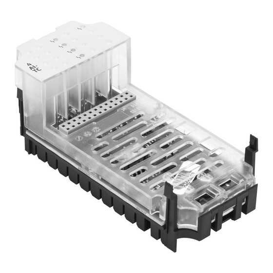
Field bus status and CPX-specific LEDs Fieldbus connection (9-pin Sub-D socket) DIL switch cover Service interface for handheld terminal (CPX-MMI) or Festo Maintenance Tool (CPX-FMT) Fig. 2.1 Connection and display components on the bus node Festo – P.BE-CPX-FB23-24-EN – 1305a – English... -
Page 12: Dismantling And Mounting
– for plastic interlinking blocks: self-tapping screws – for metal interlinking blocks: Screws with metric thread. Both types of screws are enclosed respectively when ordering the bus node as a single part. Festo – P.BE-CPX-FB23-24-EN – 1305a – English... -
Page 13: Mounting
• Disconnect the power supply before removing the DIL switch cover. • Make sure that the seal is seated correctly when fitting the cover. • Tighten the two fastening screws at first by hand and then with max. 0.4 Nm. Festo – P.BE-CPX-FB23-24-EN – 1305a – English... -
Page 14: Arrangement Of The Dil-Switches
3. Carry out the required settings ( Section2.4.4 … 2.4.10). 4. Attach the DIL switch cover again ( Section2.4.1). Note The parameterisation via DIL switch settings is taken over only when the power supply is activated. Festo – P.BE-CPX-FB23-24-EN – 1305a – English... -
Page 15: Setting The Operating Mode
CC-Link for supplementary functions (e.g. interrogating of status information). Tab. 2.1 Operating mode Note The setting of the operating mode with the DIL switch has priority over all other set- tings. Festo – P.BE-CPX-FB23-24-EN – 1305a – English... -
Page 16: Setting The Baud Rate
10 MBd 1.2: 2.1: 2.2: (factory setting) Switch position combinations that are not presented are impermissible. Tab. 2.2 Baud rate The maximum range per segment is dependent on the baud rate ( Section2.5.2). Festo – P.BE-CPX-FB23-24-EN – 1305a – English... -
Page 17: Configuration As Function Module F24 Or F23
The factory setting of the DIP switch 3.8 is dependent on the order of the bus node. If the bus node is ordered as part of a CPX terminal, either the function module F24 or F23 can be selected during the configuration of the CPX terminal. Festo – P.BE-CPX-FB23-24-EN – 1305a – English... -
Page 18: Setting The Cc-Link Slave Address
CPX terminal. CC-Link slave addresses may only be assigned once per field bus line. Example: address 05 Example: address 26 – – × 10= – – – – – – – Address: Address: Tab. 2.5 Examples of set addresses Festo – P.BE-CPX-FB23-24-EN – 1305a – English... - Page 19 OFF OFF OFF OFF OFF OFF OFF OFF OFF OFF OFF OFF OFF Switch position combinations that are not presented are impermissible. Tab. 2.6 Setting of the addresses 33 … 64: entry of the DIL switch Festo – P.BE-CPX-FB23-24-EN – 1305a – English...
- Page 20 OFF OFF OFF OFF OFF OFF OFF OFF OFF OFF OFF OFF Switch position combinations that are not presented are impermissible. Tab. 2.7 Setting of the addresses 1 … 32: entry of the DIL switch Festo – P.BE-CPX-FB23-24-EN – 1305a – English...
-
Page 21: Setting Of Mapping Optimisation
The number of stations required and cycles is automatically determined by the bus node according to the selected type of optimisation (cycle time optimised or station optimised). Festo – P.BE-CPX-FB23-24-EN – 1305a – English... - Page 22 – 2 byte = Useful data volume = 10 byte = 38 byte for more than 1 cycle, required for each cycle Tab. 2.10 Determine the actual useful data in the bit range Festo – P.BE-CPX-FB23-24-EN – 1305a – English...
-
Page 23: Setting The Hold/Clear Function
– Timeout of communication Warning • Ensure that valves and outputs are put into a safe status if the stated malfunctions occur. Incorrect status of valves and outputs can lead to dangerous situations. Festo – P.BE-CPX-FB23-24-EN – 1305a – English... -
Page 24: Setting The System Diagnostics
The system diagnostics is only available in the operating mode Remote I/O. In the Remote Controller operating mode the DIL switch 5.2 has function. Further information on the status bits and I/O diagnostic interface are found Sections 3.2 and 4.5. Festo – P.BE-CPX-FB23-24-EN – 1305a – English... -
Page 25: Connecting The Fieldbus
Note the relevant regulations in IEC/EN 60204-1. Exact details on the bus length is found in section 2.5.2 and in the manuals for your control system. Festo – P.BE-CPX-FB23-24-EN – 1305a – English... -
Page 26: Fieldbus Baud Rate And Fieldbus Length
Total cable length CPX terminal with bus node CPX-FB23-24 = Remote device station Tab. 2.13 Baud rate and fieldbus length For setting the baud rate, observe the instructions in section 2.4.5. Festo – P.BE-CPX-FB23-24-EN – 1305a – English... - Page 27 More than 1 m if only remote I/Os and remote device stations are available. More than 2 m if local or intelligent device stations are available. Tab. 2.14 Specification for branch lines Festo – P.BE-CPX-FB23-24-EN – 1305a – English...
-
Page 28: Pin Allocation Of The Fieldbus Interface
Intended CC-Link cable Earthing (SLD and FG connected in the CC-Link slave (Remote Device Station) module) 1) The three cables for connection to BDA, CM and DG are twisted. Fig. 2.4 Connection assignment of CC-Link Festo – P.BE-CPX-FB23-24-EN – 1305a – English... - Page 29 Protection class IP20 Tab. 2.16 Sub-base/plug for field bus connection Note Only the Sub-D plug from Festo will comply with standard IP 65/IP67. Before using fieldbus plugs from other manufacturers: • Replace the two flat screws with bolts (type UNC-4-40/M3x6).
- Page 30 Alternatively, you can connect the CPX terminal with sub-D plug from Festo. • Observe the assembly instructions for the fieldbus plug. • Clamp the screening of the field bus cable under the clamp strap of the sub-D plug from Festo. Note The clamp strap in the field bus plug is connected internally with the metal housing of the sub-D plug.
-
Page 31: Field Bus Connection With Terminating Resistors
Installation as function module F24 Note • Note that only the Festo sub-D plug guarantees compliance with protection class IP65/IP67. To comply with protection class IP65/IP67: • Fit the DIL switch cover. • Seal the service interface with the protective cap supplied. -
Page 32: Pin Assignment Of Power Supply
The current consumption of a CPX terminal depends on the number and type of integrated modules and components. In the CPX system description, read the information on power supply as well as on the earthing measures to be carried out (P.BE-CPX-SYS-…). Festo – P.BE-CPX-FB23-24-EN – 1305a – English... -
Page 33: Commissioning As Function Module F24
For operation of the bus node CPX-FB23-24 as a function module F24 (CC-Link version 2. 0), the DIL switch element 3. 8 of the DIP-switch 3 must be set on “ON” section 2.4.6). Festo – P.BE-CPX-FB23-24-EN – 1305a – English... - Page 34 In the I / O modules, the module indicator is depicted in the upper region of the module besides the LEDs (for example, 8DI for a module with 8 digital in- puts). Detailed information on the electric and pneumatic CPX modules are found in the Festo Support Portal ( www.festo.com).
-
Page 35: Addressing Rules
– The status bits and the I/O diagnostic interface of the system diagnostics occupy, if activated, the first 2 bytes respectively of the inputs and outputs of the word range of the 1st station e.g. Fig. 3.1). Festo – P.BE-CPX-FB23-24-EN – 1305a – English... - Page 36 – CPX-CMAX-C1-2 installation position in the CPX terminal (from left to right). Only with activated system diagnostics Type of electronic module contained. Tab. 3.1 I/O counting mode: addressing rules for the CPX modules Festo – P.BE-CPX-FB23-24-EN – 1305a – English...
-
Page 37: Addressing Examples (Examples Of Address Assignment)
X1050 Remote Ready (RR = Bit 11) Y1050 D1009 AI9 D2009 D1010 AI10 AO10 D2010 D1011 AI11 AO11 D2011 Available address space Allocated address space Fig. 3.1 Example for cycle time optimised CC-Link memory mapping Festo – P.BE-CPX-FB23-24-EN – 1305a – English... - Page 38 AO12 D2012 4nd cycle X1070 Y1070 D1013 AI13 AO13 D2013 D1014 AI14 AO14 D2014 D1015 AI15 AO15 D2015 Available address space Allocated address space Fig. 3.2 Example for station optimised CC-Link memory mapping Festo – P.BE-CPX-FB23-24-EN – 1305a – English...
- Page 39 (9 words) (3 words) Module identifiers on the Festo Maintenance Tool (CPX-FMT) or handheld (CPX-MMI) for I/O mod- ules these are shown in the inspection window of the module. Remote Ready bit always occupies the address space of 2 bytes in the bit range (RX, RY) at the end of the last station with 1 bit.
- Page 40 Outputs (RY, RWw) Allocated address space Available address space X1000, Y1000, D1000, D2000… Exemplary representation of the CC-Link address assignment (hexadecimal) Fig. 3.3 Optimised cycle time addressing of the CPX terminal described in theTab. 3.2 Festo – P.BE-CPX-FB23-24-EN – 1305a – English...
- Page 41 Outputs (RY, RWw) Allocated address space Available address space X1000, Y1000, D1000, D2000… Exemplary representation of the CC-Link address assignment (hexadecimal) Fig. 3.4 Station-optimised addressing of the CPX terminal described in theTab. 3.2 Festo – P.BE-CPX-FB23-24-EN – 1305a – English...
-
Page 42: Address Assignment After Extension/Conversion
For station optimisation, the last 2 bytes respectively in the bit range (RX and RY) of the immediately following free cycle address space are reserved ( Fig. 3.2). Bit 11 of the input section (RX) includes the Remote Ready bit. Festo – P.BE-CPX-FB23-24-EN – 1305a – English... - Page 43 = assigned CC-Link slave address Q = quitting bit; S = control bit Tab. 3.3 System diagnostic: status bits and I/O diagnostic interface Detailed information on system diagnostics is found in the CPX system description (P.BE-CPX-SYS-…). Festo – P.BE-CPX-FB23-24-EN – 1305a – English...
-
Page 44: Fieldbus Configuration
Link master and for the relevant control systems (e.g. from Mitsubishi). An overview can be found under www.cc-link.org. Note In a configuration with 1-fold cycle setting ( Tab. 2.9) the bus node in the master must be configured as CC-Link 1.1 slave. Festo – P.BE-CPX-FB23-24-EN – 1305a – English... -
Page 45: Parameterisation
General information regarding operation of the handheld and commissioning of the CPX terminal with the handheld is found in the description of handheld device. The current version of the PC software CPX Festo Maintenance Tool (CPX-FMT) is found on the website of Festo ( www.festo.com). -
Page 46: Parameters Of The Cpx Terminal
“System start with default parameters and the current CPX expansion”. Subsequently, the startup parameters should be reset to “System start with saved parameterisation and saved CPX expansion” and the CPX terminal will now be reconfigured as needed. Festo – P.BE-CPX-FB23-24-EN – 1305a – English... -
Page 47: Parameterisation Concepts
– Expensive system description). master. programming. 1) Front end controller (FEC and/or CEC) in CPX terminal required 2) USB adapter (connecting cable), type NEFC-M12G5-0.3-U1G5 ( www.festo.com) Tab. 3.4 Parameterisation Festo – P.BE-CPX-FB23-24-EN – 1305a – English... -
Page 48: Commissioning Of The Cpx Terminal On The Fieldbus
– When a station is linked into the system again after a fault has been eliminated, it is not necessary to reset the master station. Monitoring the communication status – The network can be monitored by the master station during system set-up, during debugging or during maintenance. Festo – P.BE-CPX-FB23-24-EN – 1305a – English... -
Page 49: Operation As Function Modules F24 To Cc-Link Master Version
If through conversion or extension of the CPX terminal, the address space supported by the CC-Link version 1.1 is exceeded, the bus node changes to CC-Link version 2.0. Com- munication with a V1.1 control is no longer possible. Festo – P.BE-CPX-FB23-24-EN – 1305a – English... -
Page 50: Diagnostics And Error Handling
Additional information on general diagnostics of the CPX terminal is found in the CPX system description (P.BE-CPX-SYS-...). Information on diagnostics of the pneumatics, of the pneumatic interface and of the I/O module are found in the corresponding descriptions. Festo – P.BE-CPX-FB23-24-EN – 1305a – English... -
Page 51: Overview Of Diagnostics Options
Tab. 4.1 Diagnostics options Note Note that the diagnostic information is dependent on the DIL switch settings on the bus node, ( section 2.4.10) as well as on the parameterisation of the CPX terminal. Festo – P.BE-CPX-FB23-24-EN – 1305a – English... -
Page 52: Error Messages Of The Bus Node Cpx-Fb23-24
If the system boundary of the CPX terminal is exceeded by complex expansion of the max- imum possible address space, the commissioning of the CPX terminal is not possible. The error will be displayed on the bus node of the “SF LED”. Festo – P.BE-CPX-FB23-24-EN – 1305a – English... -
Page 53: Diagnostics Via Leds
– PL (green) – ERROR (red) – SF (red) *) – SD (yellow) – M (yellow) – RD (yellow) The SF LED also shows CC-Link-specific faults Fig. 4.1 LEDs on the CPX bus node CPX-FB23-24 Festo – P.BE-CPX-FB23-24-EN – 1305a – English... -
Page 54: Normal Operating Status
– PS – PL The red LEDs do not light up: – error – SF Yellow LEDs light up or flash (depending on the data communication or configuration) – SD – RD – M Festo – P.BE-CPX-FB23-24-EN – 1305a – English... -
Page 55: Cpx-Specific Leds
Status Significance / error handling No error. Load voltage – applied LED illumin- ated Load voltage at the system • Eliminate undervoltage supply or additional power LED flashes supply outside the tolerance range Festo – P.BE-CPX-FB23-24-EN – 1305a – English... - Page 56 Force is active The Force function is enabled. LED flashes 1) The display of the Force function (LED flashes) has priority over the display of the setting for the system start (LED lights up). Festo – P.BE-CPX-FB23-24-EN – 1305a – English...
-
Page 57: Cc-Link-Specific Leds
LED not illuminated RD – Receive Data LED (yellow) Process Status Significance / error handling CPX terminal receives data Section 4.4.4 illuminated CPX terminal does not receive any data LED not illuminated Festo – P.BE-CPX-FB23-24-EN – 1305a – English... -
Page 58: Possible Operating States Of Cc-Link-Specific Leds
No data reception possible, e.g. due to wire fracture, power OFF/ON required. Fault in baud rate and/or CC-Link slave address. LED lights up; LED flashes; LED is out Tab. 4.3 Overview CC-Link LEDs Festo – P.BE-CPX-FB23-24-EN – 1305a – English... -
Page 59: Diagnostics Via Field Bus Cc-Link
Errors can be uniquely defined via the I/O diagnostics interface. Further instructions on the function and content of the status bits are found in the CPX system description (P.BE-CPX-SYS-…). Festo – P.BE-CPX-FB23-24-EN – 1305a – English... -
Page 60: I/O Diagnostic Interface
2 bytes respectively of the inputs and outputs of the word range of the Station 1 ( e.g. Fig. 3.1). Instructions on diagnostics with the I/O diagnostics interface are found in the CPX system description (P.BE-CPX-SYS-…). Festo – P.BE-CPX-FB23-24-EN – 1305a – English... -
Page 61: Function Module F23
The instructions and descriptions for assembly in this chapter with exception of section 2.4.8 are valid also for the configuration as a function module F23. For the function module F23, section 5.2.1 is valid instead of the section 2.4.8. Festo – P.BE-CPX-FB23-24-EN – 1305a – English... -
Page 62: Setting The Number Of Stations Per Slave / Number Of I/O Bytes
FEC integrated in the CPX terminal or CEC, 8 I/O bytes are as- signed. Further information on the number of stations per slave can be found in section 2.4.7. Observe the general rules on addressing in the manual for your CC-Link master. Festo – P.BE-CPX-FB23-24-EN – 1305a – English... -
Page 63: Commissioning
– The maximum possible extension of the CPX terminal is defined by the maximum number of modules and the set number of stations. Detailed information on the electric and pneumatic modules are found in the Festo Sup- port Portal ( www.festo.com). - Page 64 – The following I/Os are assigned separately from each other: – Remote Ready (RR, CC-Link-specific reserved, always lies in the last reserved station) – diagnostic I/Os (only if configured) – for digital I/Os – analogue I/Os, I/Os of function modules Festo – P.BE-CPX-FB23-24-EN – 1305a – English...
- Page 65 – CPX-CMAX-C1-2 next to the other – Maximum 4 stations can be assigned Only with activated system diagnostics Type of electronic module contained. Tab. 5.2 I/O counting mode: addressing rules for the CPX modules Festo – P.BE-CPX-FB23-24-EN – 1305a – English...
- Page 66 I = digital input Remote Ready (RR = 1 Reserved Reserved O = digital output Bit 11) 2 Reserved Reserved 3 Reserved Reserved Fig. 5.1 CC-Link memory mapping ( 16 digital inputs and outputs) Festo – P.BE-CPX-FB23-24-EN – 1305a – English...
- Page 67 Reserved Control 0 AI12 AO12 Station 4 Remote Ready (RR = 1 AI13 AO13 Bit 11) 2 AI14 AO14 3 AI15 AO15 Fig. 5.3 CC-Link memory mapping (≤ 16 analogue inputs and outputs) Festo – P.BE-CPX-FB23-24-EN – 1305a – English...
- Page 68 Control 0 AI 4 Station 4 Remote Ready (RR = Bit 11) 1 AI5 2 AI6 3 AI7 Fig. 5.5 CC-Link memory mapping (≤ 64 digital and ≤ 8 analogue inputs and outputs) Festo – P.BE-CPX-FB23-24-EN – 1305a – English...
-
Page 69: Bus Node
(2 words) (2 words) Module identifiers on the Festo Maintenance Tool (CPX-FMT) or handheld (CPX-MMI) for I/O mod- ules these are shown in the inspection window of the module. Remote Ready bit is always assigned at the end of the last station with 1 bit address space of 2 bytes in the bit range (RX, RY). - Page 70 (RY, RWw) allocated address space available address space X1000, Y1000, D1000, D2000… Exemplary representation of the CC-Link address assignment (hexadecimal) Fig. 5.6 Addressing within the CPX terminal in the example from Tab. 5.3 Festo – P.BE-CPX-FB23-24-EN – 1305a – English...
-
Page 71: Address Assignment After Extension/Conversion
Bit 11 of the input section (RX) includes respectively the Remote Ready bit. Digital inputs and outputs (I/Os) Digital I/Os occupy from the first station, if it is not allocated to analog I/Os, one after the other the bit range (RX/RY) ( section 5.3.1). Festo – P.BE-CPX-FB23-24-EN – 1305a – English... - Page 72 Control bit for the relevant analogue output. The relevant output is reset with a 0-signal. assigned CC-Link slave address 1. Station: m = 0 2. Station: m = 2 3. Station: m = 4 4. Station: m = 6 Tab. 5.4 Control Festo – P.BE-CPX-FB23-24-EN – 1305a – English...
- Page 73 4.5.1) Master > Slave – RWw(n)0 Bit: Signal: S Reserved Function number assigned CC-Link slave address quitting bit; S = control bit Tab. 5.6 System diagnostic: I/O diagnostic interface and status bits Festo – P.BE-CPX-FB23-24-EN – 1305a – English...
-
Page 74: Fieldbus Configuration
The instructions and descriptions for commissioning in the section 3.4.1 and 3.4.3 are also valid for the function module F23. The descriptions of the section 3.4.2 are to be replaced for the function module F23 by section 5.5.1. Festo – P.BE-CPX-FB23-24-EN – 1305a – English... -
Page 75: Run/Pause And Stop Of The Master
The analogue outputs will then also be set. General notes on diagnostics and error handling The instructions and descriptions for diagnostics and error handling in the sections 4.1 and 4.5.2 are also valid for the function module F23. Festo – P.BE-CPX-FB23-24-EN – 1305a – English... -
Page 76: A Technical Appendix
Internal current consumption at 24 V (internal elec- tronics): Typically 70 mA – From operating voltage supply for electron- ics/sensors (U EL/SEN Galvanic isolation – Between bus interface and CPX periphery (power supplies) Festo – P.BE-CPX-FB23-24-EN – 1305a – English... -
Page 77: Default Parameterisation
System start 4402 System start with de- Defines the starting reaction of the CPX terminal. fault parameterisation Saves current parameter settings. (factory setting) and current CPX expansion. Tab. A.1 System parameters Festo – P.BE-CPX-FB23-24-EN – 1305a – English... -
Page 78: Accessories
Fault number (FN) 3487 Fault number 0 Fault number for the diagnostic memory filter Tab. A.2 Diagnostic memory parameters Accessories • Accessories are found in our online catalogue ( www.festo.com/catalogue) on the Internet. Festo – P.BE-CPX-FB23-24-EN – 1305a – English... -
Page 79: B Glossary
With the aid of parameterisation, the characteristics of the CPX terminal or the characteristics of the individual modules and I/O channels can be adapted to each particular application. Parameters can be read and modified. PLC/IPC Programmable logic controller/industrial PC Festo – P.BE-CPX-FB23-24-EN – 1305a – English... - Page 80 Sum of the maximum possible dataset that can be occupied by digital and analog inputs and outputs, of CPX modules in the corresponding address space of the bus node. Tab. B.1 CPX specific and/or CC-Link specific terms and abbreviations Festo – P.BE-CPX-FB23-24-EN – 1305a – English...
- Page 81 ... Power supply ......Festo – P.BE-CPX-FB23-24-EN – 1305a – English...
- Page 82 ....28, 31 – I/O diagnostic interface ....Festo – P.BE-CPX-FB23-24-EN – 1305a – English...
- Page 84 Copyright: Festo AG & Co. KG Postfach 73726 Esslingen Germany Phone: +49 711 347-0 Fax: +49 711 347-2144 e-mail: service_international@festo.com Reproduction, distribution or sale of this document or communica- Internet: tion of its contents to others without express authorization is www.festo.com...
Need help?
Do you have a question about the CPX Series and is the answer not in the manual?
Questions and answers