Festo CPX Series Manual
Bus node, network protocol profinet io
Hide thumbs
Also See for CPX Series:
- Manual (446 pages) ,
- Electronic manual (232 pages) ,
- Description (156 pages)

Related Manuals for Festo CPX Series


Summary of Contents for Festo CPX Series
- Page 1 CPX Terminal Manual Electronics CPX bus node Type CPX−FB33 Type CPX−M−FB34 Type CPX−M−FB35 Network protocol PROFINET IO Manual 548 760 en 1008b [752 465]...
- Page 3 ....... . . 548 760 © (Festo AG & Co. KG, D 73726 Esslingen, Germany, 2010) Internet: http://www.festo.com E−Mail:...
- Page 4 Contents and general instructions ® ® ® ® ® ® PROFINET IO , PROFIBUS , SIMATIC , TORX , TÜV and VDE are registered trademarks of the respective trademark owners in certain countries. Festo P.BE−CPX−PN IO−EN en 1008b...
-
Page 5: Table Of Contents
......... . . 2−18 Festo P.BE−CPX−PN IO−EN en 1008b... - Page 6 ......2−60 2.8.4 Parametrisation via the Festo Maintenance Tool ....2−60 2.8.5...
- Page 7 ............C−1 Festo P.BE−CPX−PN IO−EN en 1008b...
- Page 8 Contents and general instructions Festo P.BE−CPX−PN IO−EN en 1008b...
-
Page 9: Intended Use
The limit values specified for pressures, temperatures, electrical data, torques etc. should be observed. If conventional accessory components such as sensors and actuators are connected, the specified limits for pressures, temperatures, electrical data, torques etc. should be observed. Festo P.BE−CPX−PN IO−EN en 1008b... -
Page 10: Target Group
(PLC) and field bus systems. Service Please consult your local Festo Service agent if you have any technical problems. VIII Festo P.BE−CPX−PN IO−EN en 1008b... -
Page 11: Instructions On This Manual
PROFINET: 650 nm wavelength, suitable for POF fibre−optic cable, PROFINET Installation Guide AIDA−conforming, IEC 61158 corresponding to IEC 61754−24 IEC 61784 IEC 61918 Further information: http://www.profinet.com Tab. 0/1: Overview of CPX bus node for PROFINET Festo P.BE−CPX−PN IO−EN en 1008b... - Page 12 An overview of the structure of the CPX−terminal user documentation is contained in the CPX system description (P.BE−CPX−SYS...). Product specific information about the control system (IPC, PLC or I/O controller) can be found in the manufacturer’s product documentation accompanying the product. Festo P.BE−CPX−PN IO−EN en 1008b...
-
Page 13: Important User Instructions
This means that failure to observe this instruction may result in damage to property. The following pictogram marks passages in the text which describe activities with electrostatically sensitive components. Electrostatically sensitive components may be damaged if they are not handled correctly. Festo P.BE−CPX−PN IO−EN en 1008b... - Page 14 Accessories: Information on necessary or sensible accessories for the Festo product. Environment: Information on environment−friendly use of Festo products. Text markings The bullet indicates activities which may be carried out in · any order. 1. Figures denote activities which must be carried out in the numerical order specified.
- Page 15 System controller (PLC, remote controller operating mode) Fieldbus slave (Remote I/O operating mode) Festo Maintenance Tool (CPX−FMT); configuration and programming software for CPX modules for start−up and service purposes Fibre−optic cable (FOC, fibre optics) Fibre−optic cables...
- Page 16 Fieldbus system based on Industrial Ethernet for data exchange be tween system controller (PLC/IPC), plant controller (e.g. CPX−FEC) and field devices (I/O devices) or drives and valve terminals; for further information: http://www.profinet.com Tab. 0/3: Specific terms and abbreviations part 2 Festo P.BE−CPX−PN IO−EN en 1008b...
- Page 17 (typical cycle time: < 1 ms; typical application: drive controller) Programmable logic controller, also designated system controller or controller for short (see also PLC) I/O diagnostic interface (System Table Interface) Tab. 0/4: Specific terms and abbreviations part 3 Festo P.BE−CPX−PN IO−EN en 1008b...
- Page 18 Contents and general instructions Festo P.BE−CPX−PN IO−EN en 1008b...
-
Page 19: Installation
Installation Chapter 1 1−1 Festo P.BE−CPX−PN IO−EN en 1008b... - Page 20 ........1−27 1−2 Festo P.BE−CPX−PN IO−EN en 1008b...
-
Page 21: General Instructions On Installation
Observe the handling specifications for electrostatically · sensitive devices. You avoid malfunctions of and damage to the electronics by doing so. Information about fitting the CPX terminal can be found in the CPX system manual (P.BE−CPX−SYS−...). 1−3 Festo P.BE−CPX−PN IO−EN en 1008b... -
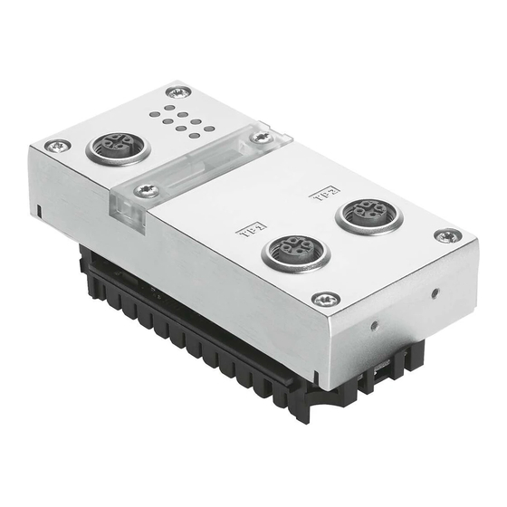
Page 22: Electrical Connection And Display Components
CPX−M−FB35: 2 x SCRJ, push−pull, Fig. 1/1: Connection and display components on the CPX bus node Note Use protective caps or blanking plugs to seal unused connections. You will then comply with protection class IP65/IP67 (see section 1.7). 1−4 Festo P.BE−CPX−PN IO−EN en 1008b... -
Page 23: Dismantling And Mounting Of The Bus Node
2. Pull the bus node carefully and without tilting away from the contact rails of the interlinking block. CPX bus node (Example CPX−FB33) Interlinking block Contact rails Torx T10 screws, tightening torque: 0.9 ... 1.1 Nm Fig. 1/2: Dismantling/mounting the bus node 1−5 Festo P.BE−CPX−PN IO−EN en 1008b... - Page 24 3. Carefully push the bus node into the interlinking block up to the stop. 4. Place the screws so that the self−cutting threads can be used. 5. Tighten the screws with a size T10 Torx screwdriver with 0.9 ... 1.1 Nm of torque. 1−6 Festo P.BE−CPX−PN IO−EN en 1008b...
-
Page 25: Setting The Dil Switches, Use Of The Memory Card
Disconnect the power supply before removing the cover. · Make sure that the seal is seated correctly when · attaching the cover. Tighten the two fastening screws at first by hand and · then with max. 0.4 Nm. 1−7 Festo P.BE−CPX−PN IO−EN en 1008b... -
Page 26: Settingthe Dil Switches
(remote I/O operating mode only); Datafield size (only in remote controller operating mode) Memory card (see section 1.4.3, 1.5 as well as 2.6.3 and 2.8.1) Fig. 1/3: Settings of the DIL switches on the bus node 1−8 Festo P.BE−CPX−PN IO−EN en 1008b... - Page 27 Further explanations of the bus node operating mode can be found in section B.1: Remote I/O operating mode è section B.1.1 Remote controller operating mode è section B.1.2 Additional function Fast Start−up" (FSU) è section B.1.3 1−9 Festo P.BE−CPX−PN IO−EN en 1008b...
- Page 28 Diagnostics mode status bits occupy 1 byte of address space (8 I bits) Diagnostics mode I/O diagnostics interface occupies 4 bytes of address space (16 I and 16 O bits) Tab. 1/2: Setting the diagnostics mode with DIL switch (in remote I/O operating mode) 1−10 Festo P.BE−CPX−PN IO−EN en 1008b...
- Page 29 To do this, repeat the hardware and network configuration in your configuration and programming software (e.g. Siemens SIMATIC STEP 7), especially assignment of the inputs and outputs (see section 2.7.1 and section 2.7.2). 1−11 Festo P.BE−CPX−PN IO−EN en 1008b...
- Page 30 CPX Rev 11 for bus node up to CPX revision code Rev 11 Prioritized Start−up, from GSDML file V. 2.2 + Rev 12 Tab. 1/3: Bus node selection (station symbol or field device group) dependent on operating mode, diagnostics mode and additional function FSU 1−12 Festo P.BE−CPX−PN IO−EN en 1008b...
- Page 31 16 bytes I/16 bytes O DIL 2.1: Reserved for future extensions DIL 2.2: DIL 2.1: Reserved for future extensions DIL 2.2: Tab. 1/4: Setting the datafield size with DIL switch (in remote controller operating mode) 1−13 Festo P.BE−CPX−PN IO−EN en 1008b...
-
Page 32: Use Of The Memory Card
Disconnect the power supply before you insert or · remove the memory card. Replacement The memory card is located under a cover (see Fig. 1/1). of the memory card You need a screwdriver in order to remove or attach this cover. 1−14 Festo P.BE−CPX−PN IO−EN en 1008b... -
Page 33: Replacement Of The Bus Node
Inserting or removing the memory card while the power supply is switched on can result in malfunctions of or damage to the memory card. Disconnect the power supply before you insert or · remove the memory card. 1−15 Festo P.BE−CPX−PN IO−EN en 1008b... - Page 34 4. Start your configuration and programming software (e.g. Siemens STEP 7). 5. Perform a new configuration (hardware configuration, in STEP 7 using HW Config). 6. The controller loads all required data into the bus node. 1−16 Festo P.BE−CPX−PN IO−EN en 1008b...
-
Page 35: Connecting To The Network
PELV power supplies or integrated power supplies with similar protection. Installation guidelines The installation guidelines can be obtained via the PROFINET User Organisation: è Internet: http://www.profinet.com è Internet: http://www.profibus.com/downloads Observe the instructions there. 1−17 Festo P.BE−CPX−PN IO−EN en 1008b... - Page 36 Note Make sure that any intermediate switches and routers support the PROFINET function Fast Start−up" (FSU) when you use this additional function. Further information on FSU can be found in section B.1.3. 1−18 Festo P.BE−CPX−PN IO−EN en 1008b...
- Page 37 2 x SCRJ sockets, push−pull connection, Plug from Festo, 650 nm wavelength, suitable for POF Type FBS−SCRJ−PP−GS fibre−optic cable, AIDA−compliant, corresponding to IEC 61754−24 è Internet: www.festo.com/catalogue/ Tab. 1/5: Overview of connection technology and network plugs 1−19 Festo P.BE−CPX−PN IO−EN en 1008b...
- Page 38 (I/O devices, see Fig. 1/4): Crossover cable with the same assignment of the ports Patch cable with different assignment of the ports Observe the following note regarding pin allocation of · port TP2. 1−20 Festo P.BE−CPX−PN IO−EN en 1008b...
- Page 39 Switch port, e.g. of the PLC Patch cable (crossover" pin allocation) Terminal port of an I/O device Fig. 1/4: Wiring of the I/O devices for Fast Start−up" with deactivated crossover" detection or autonegotiation" (configuration example) 1−21 Festo P.BE−CPX−PN IO−EN en 1008b...
- Page 40 Length corresponding to specification for PROFINET networks (PROFINET Installation Guide) based on ISO/IEC 11801, ANSI/TIA/EIA−568 (see also section 1.6.1) è Internet: www.profinet.com, www.profibus.com/downloads Tab. 1/6: Overview of line specification (in combination with Festo bus node and Festo network plug) 1−22 Festo P.BE−CPX−PN IO−EN en 1008b...
-
Page 41: Network Interface Of The Cpx−Fb33
Pin allocation of the network interfaces of the CPX−FB33 (M12) Connection with plug from Festo Connect the CPX terminal to the network with Festo plugs type NECU−M−S−D12G4−C2−ET. The plug is designed for Ethernet cable with cable diameters of 6 ... 8 mm. -
Page 42: Network Interface Of The Cpx−M−Fb34
Pin allocation of the network interfaces of the CPX−M−FB34 (RJ45) Connection with plug from Festo Connect the CPX terminal to the network with Festo plugs, type FBS−RJ45−PP−GS. The plug is designed for Ethernet cable with cable diameters of 5 ... 8 mm. -
Page 43: Network Interface Of The Cpx−M−Fb35
Pin allocation of the network interfaces of the CPX−M−FB35 (SCRJ) Connection with plug from Festo Connect the CPX terminal to the network with Festo plugs, type FBS−SCRJ−PP−GS. The plug is designed for POF fibre−optic cable with cable diameter of 6.5 ... 9.5 mm. -
Page 44: You Will Then Comply With Protection Class Ip65/Ip67
Cover cap from Festo, CPX−MMI + CPX−FMT of the CPX−MMIs or CPX−FMTs Type ISK−M12 if connection is not used included in scope of supply, always cover unused connection Tab. 1/10: Connections and covers for protection class IP65/IP67 1−26 Festo P.BE−CPX−PN IO−EN en 1008b... -
Page 45: Pin Assignment Of Power Supply
The current consumption of a CPX terminal depends on the number and type of integrated modules and components. Observe the information on power supply and the required earthing measures in the CPX system description. 1−27 Festo P.BE−CPX−PN IO−EN en 1008b... - Page 46 Pay attention to the information on the plug (regarding allocation of the connection pins A, B, C, D). Interlinking blocks with push−pull connection and with forwarding function or with system supply are identically constructed. Tab. 1/11: Pin assignment for system supply, additional supply and valve supply 1−28 Festo P.BE−CPX−PN IO−EN en 1008b...
- Page 47 Commissioning Chapter 2 2−1 Festo P.BE−CPX−PN IO−EN en 1008b...
-
Page 48: Commissioning
......2−60 2.8.4 Parametrisation via the Festo Maintenance Tool ....2−60 2.8.5... -
Page 49: General Information
1. Switch on the operating voltage supply of all bus subscribers (I/O devices). 2. Switch on the operating voltage supply for the controller. 2−3 Festo P.BE−CPX−PN IO−EN en 1008b... - Page 50 (see section 2.6). Parametrisation A CPX terminal in the PROFINET network can be parametrised through the control system (PLC/IPC), a handheld control unit (CPX−MMI) or the Festo Maintenance Tool (CPX −FMT) (see section 2.8). 2−4 Festo P.BE−CPX−PN IO−EN en 1008b...
-
Page 51: Address Assignment
Tab. 2/8 assists you with this. Use the configuration documents, the handheld control unit (CPX−MMI) or the Festo Maintenance Tool (CPX−FMT) to determine address assignment or terminal configuration. In the handheld display, the individual modules of the CPX terminal are displayed with the respective module identifiers. - Page 52 (see Tab. 2/1). In the remote I/O (RIO) operating mode, the identifiers of the bus node (including diagnostics mode), the CPX modules and, if present, the pneumatics modules are configured (see Tab. 2/2). 2−6 Festo P.BE−CPX−PN IO−EN en 1008b...
- Page 53 Diagnostics mode status bits assigned 16 I or 2 bytes of address space (8 I or 8 bits remain unused) Tab. 2/2: Address allocation of the bus nodes for the remote I/O operating mode 2−7 Festo P.BE−CPX−PN IO−EN en 1008b...
- Page 54 4−way modules (CPX−4DE and CPX−4DA) occupy 8 I or 8 O or 1 byte of address space (4 I/O or 8 bits of address space remain unused) Tab. 2/3: Address assignment of electric CPX modules (overview; bus node in remote I/O operating mode) part 1 2−8 Festo P.BE−CPX−PN IO−EN en 1008b...
- Page 55 Address space assignment dependent on the string allocation (4 bytes I or 4 bytes O per string) Tab. 2/4: Address assignment of electric CPX modules (overview; bus node in remote I/O operating mode) part 2 2−9 Festo P.BE−CPX−PN IO−EN en 1008b...
- Page 56 2 bytes of I or 16 inputs. } Pneumatic modules of type VPPM each occupy 4 bytes of address space, i.e. 2 bytes of I / 2 bytes of O or 16 inputs and 16 outputs. 2−10 Festo P.BE−CPX−PN IO−EN en 1008b...
- Page 57 The descriptions for the pneumatic valve terminal (Midi/Maxi, CPA, MPA and VTSA/VTSA−F or ISO) contain the address assignment within the pneumatic modules. For further information on MPA pneumatic modules and the pneumatic interfaces: see manual for the CPX I/O modules (P.BE−CPX−EA−...). 2−11 Festo P.BE−CPX−PN IO−EN en 1008b...
- Page 58 Module identifier in the handheld unit or in the hardware configuration of the programming software 4−way modules MPA2 always occupy 8 I (1 byte) of address space (4 I or 8 bits remain unused) Tab. 2/5: Overview of CPX pneumatic interfaces and pneumatic modules (part 1) 2−12 Festo P.BE−CPX−PN IO−EN en 1008b...
- Page 59 Observe the order of the modules in addressing or I/O mapping (see Tab. 2/9). MPAF−P is also called end plate" with pressure sensor or pressure sensor plate Tab. 2/6: Overview of CPX pneumatic interfaces and pneumatic modules (part 2) 2−13 Festo P.BE−CPX−PN IO−EN en 1008b...
- Page 60 Module identifier in the handheld unit or in the hardware configuration of the programming software Setting with DIL switch in the pneumatic interface Display text (module identifier) dependent on the version of the handheld unit Tab. 2/7: Overview of CPX pneumatic interfaces and pneumatic modules (part 3) 2−14 Festo P.BE−CPX−PN IO−EN en 1008b...
- Page 61 4−way modules CPX−4DE and CPX−4DA as well as MPA2 pneumatic modules always occupy 8 inputs or outputs (1 byte; available address space remains partially unused) Tab. 2/8: Identifying the assigned address space (total of inputs and outputs) 2−15 Festo P.BE−CPX−PN IO−EN en 1008b...
-
Page 62: Addressing
If the 8 status bits are activated, they will occupy the first 16 inputs in the address range (8 used). If the I/O diagnostic interface is activated, it will occupy the first 16 inputs and 16 outputs in the address range. 2−16 Festo P.BE−CPX−PN IO−EN en 1008b... - Page 63 Move the modules originally configured in this address space into another area. Configuration of these modules must be repeated, if necessary (see also section 2.7 regarding configuration with PROFINET configuration and programming software, e.g. Siemens SIMATIC STEP 7). 2−17 Festo P.BE−CPX−PN IO−EN en 1008b...
-
Page 64: Address Assignment And Addressing After Expansion Or Conversion
(see Pneumatics description). if additional manifold sub−bases (CPA) or sub−bases (Midi/Maxi) are inserted between existing sub−bases. The diagnostic mode (status bits or the I/O diagnostic interface) is activated/deactivated. 2−18 Festo P.BE−CPX−PN IO−EN en 1008b... -
Page 65: Instructions For Commissioning With Siemens Simatic Step 7
Controller (PLC/CPU) Siemens SIMATIC S7−317 with FW V. 2.5.x Control software Siemens STEP 7 V. 5.4 for the Prioritized Start−up" operating mode · (Fast Start−up): GSDML/PNIO specification V. 2.2 Controller (PLC/CPU) Siemens SIMATIC S7−319 with FW V. 2.7.x 2−19 Festo P.BE−CPX−PN IO−EN en 1008b... - Page 66 Please take information on other variants from the documents on your controller and control software. In case of technical problems, please first contact the respective manufacturer. In cases of doubt, your local Festo Service is happy to help you further. Note There are different configuration programs available for a Siemens PLC.
-
Page 67: Preparing For Commissioning
Upload the current GSDML file to your controller system: Click on the download arrow è in the section PROFINET · (GSDML)", and save the file Festo−GSDML.exe". Double click on the saved file Festo−GSDML.exe" to · unpack the contents (self−unpacking ZIP file): one or more GSDML files: GSDML−V...−Festo−CPX−.. -
Page 68: Select Gsdml File (Compatibility Table)
2.5.2 before installing the GSDML file. Installation of the GSDML file is explained in section 2.5.5. Symbol files The symbol files serve to depict Festo CPX terminals in your configuration software. Normally, the control system automatically includes the symbol files (during installation of the GSDML file, see section 2.5.5). - Page 69 GSDML file V. 2.1 (or possibly 2.2) For example, GSDML file GSDML−V2.1−Festo−CPX−20090702.xml"; Please observe: Version 2.1 is not officially approved and published; Festo therefore accepts no responsibility for malfunctions and effects connected to them For example, GSDML file GSDML−V2.2−Festo−CPX−20100517.xml";...
-
Page 70: Setting Up An Automation Project
4. Select the controller used (PLC/Master): Insert > Station > ... (e.g. SIMATIC 300 Station). 5. Open the project by clicking on the plus symbol (on the left next to the project symbol and the project name). 2−24 Festo P.BE−CPX−PN IO−EN en 1008b... -
Page 71: Setting Up The Controller System (Plc/Master)
The child window symbolises the rack rail (profile rail) of your controller system. You compile the individual elements of your controller in this child window and thus form the basis for your PROFINET automation system. 2−25 Festo P.BE−CPX−PN IO−EN en 1008b... - Page 72 Alternatively, you can also double click on the catalogue element: Select the next free row (insert position, slot) in the rack rail window before you make the double click. Row 1 (Slot 1) is reserved and cannot be used for the configuration. 2−26 Festo P.BE−CPX−PN IO−EN en 1008b...
-
Page 73: Installing Gsdml File
Options > Update Catalogue. All available CPX modules in the hardware catalogue are displayed under PROFINET IO > Additional Field Devices > Valves > Festo CPX Terminal. You can start the selection and configuration of your modules (see section 2.6). -
Page 74: Basic Hardware Configuration
4. Mark your searched−for CPX terminal in the list (recognisable e.g. from the MAC−ID) and click on Flashing on". The LEDs TP1 and TP2 of the bus node at the found CPX terminal flash for clear identification. 2−28 Festo P.BE−CPX−PN IO−EN en 1008b... - Page 75 This device name is also stored on the memory card (provided it is inserted) of the bus node. 5. Enter a device name in the Device name" field (e.g. CPX or CPX−01) and confirm the entry by clicking on Assign name". 2−29 Festo P.BE−CPX−PN IO−EN en 1008b...
-
Page 76: Select Cpx Terminal (Station Selection)
Fig. 2/6: Station selection using Siemens STEP 7 − HW Config 2. If the Hardware Catalogue has not been opened: Click on the catalogue symbol ( 1 in Fig. 2/6) or use the keyboard combination [Ctrl] + [K]. The hardware catalogue is displayed. 2−30 Festo P.BE−CPX−PN IO−EN en 1008b... - Page 77 (see section 2.5.2 or Tab. 2/2) Operating mode of the bus node (see section 1.4.2 or Tab. 1/1) Additional function Fast Start−up" (for short FSU, see section B.1.3) Connection technology (M12 or RJ45 or SCRJ) 2−31 Festo P.BE−CPX−PN IO−EN en 1008b...
- Page 78 5. Drag the selected station symbol 1 onto the bus line of the PROFINET IO system ( 2 in Tab. 2/3). The CPX terminal is displayed as a symbol ( 3 see also Tab. 2/1) and connected to the bus of the PROFINET IO system. 2−32 Festo P.BE−CPX−PN IO−EN en 1008b...
-
Page 79: Assign Device Name
CPX terminal (see section 2.6.1), you can skip the steps 6. and 7.. 6. Double click on the symbol of the CPX terminal 3. Assign device name The Properties CPX" window is displayed (see Fig. 2/8). 2−33 Festo P.BE−CPX−PN IO−EN en 1008b... - Page 80 7. In the Device Name" field ( 1 in Fig. 2/8) or Name" ( 1 in Fig. 2/9), enter a unique device name for the CPX terminal: e.g. CPX−01, Station−xy or an application−specific designation. 2−34 Festo P.BE−CPX−PN IO−EN en 1008b...
-
Page 81: Set Up Prioritized Start−Up (Fast Start−Up")
This operating mode allows faster system start−up times. Prioritized Start−up" is also designated Fast Start−up" (abbreviated FSU). If you do not want to use Fast Start−up", you can omit steps 8. to 20. 2−35 Festo P.BE−CPX−PN IO−EN en 1008b... - Page 82 8. Place a check in front of Prioritized Startup" 2 in the Activate Fast Start−up" window Properties CPX" (see Fig. 2/9). 9. Choose the tab IO Cycle" ( 1 in Fig. 2/10). Fig. 2/10: Fast−Start−up" settings adaptation of the I/O cycle time (Update time) 2−36 Festo P.BE−CPX−PN IO−EN en 1008b...
- Page 83 14. Double click in the configuration line of the connection (port) X1 TP1". The window Properties CPX FSU Port 1" is displayed (see Fig. 2/11). 15. Choose the Options" tab (1 in Fig. 2/11). 2−37 Festo P.BE−CPX−PN IO−EN en 1008b...
- Page 84 16. Make sure that the following Transmission medium" for Connection" 2 is set: TP / ITP with 100 Mbps full duplex" 17. Deactivate the crossover detection 3: Place a check in front of Disable Autonegotiation". 2−38 Festo P.BE−CPX−PN IO−EN en 1008b...
-
Page 85: Assigning Or Changing Ip Address
( 1 in Fig. 2/12). For IP addressing, choose the tab Addresses" ( 1 in Fig. 2/13). The Addresses" tab or the window Properties Ethernet interface CPX" window is displayed (see Fig. 2/14 or Fig. 2/15). 2−39 Festo P.BE−CPX−PN IO−EN en 1008b... - Page 86 Fig. 2/12: CPX terminal characteristics addressing (part 1) Fig. 2/13: CPX terminal characteristics addressing (part 2) 22. Manual addressing (if required): Enter the IP address of the bus node ( 1 in Fig. 2/14 or Fig. 2/15). 2−40 Festo P.BE−CPX−PN IO−EN en 1008b...
- Page 87 2. Commissioning Fig. 2/14: CPX terminal characteristics addressing (part 3) Fig. 2/15: CPX terminal characteristics addressing (part 4) 2−41 Festo P.BE−CPX−PN IO−EN en 1008b...
-
Page 88: Use Mac Addressing
Besides the IP addresses, the MAC−ID of the bus node is also available for addressing purposes (see 1 in Fig. 2/16). The MAC−ID is located on the name plate. Fig. 2/16: CPX terminal characteristics MAC addressing 2−42 Festo P.BE−CPX−PN IO−EN en 1008b... -
Page 89: Determine Port Addresses
Manufacturer ID" and a consecutive identification of the Ethernet device, e.g. 00−0E−F0−12−3A−BC. The highlighted identification represents the Manufacturer ID", here Festo. 2.6.7 Determine port addresses Determine port addresses Addresses of the input and output ports TP1 and TP2 can be determined through the configuration table of the HW Config window, for example. -
Page 90: Cpx Terminal Configuration
Click on the catalogue symbol or use the keyboard combination [Ctrl] + [K]. The hardware catalogue is displayed. 3. In the Hardware Catalogue, open the folder: \PROFINET−IO\Additional Field Devices\Valves\Festo CPX−Terminal" (English language version of the software) \PROFINET−IO\Weitere Feldgeräte\Ventile\Festo CPX−Terminal 2−44 Festo P.BE−CPX−PN IO−EN en 1008b... - Page 91 Fig. 2/17). The configuration table ( 2 in Fig. 2/17) is displayed (below the schematic representation of the PROFINET IO system). If necessary, increase the size of this area of the HW Config window. 2−45 Festo P.BE−CPX−PN IO−EN en 1008b...
- Page 92 Choose the required bus node catalogue element based on the following Tab. 2/4 dependent on: Operating mode of the bus node (see section 1.4.2 or Tab. 1/1) Diagnostics mode of the bus node (see section 1.4.2 or Tab. 1/3) 2−46 Festo P.BE−CPX−PN IO−EN en 1008b...
- Page 93 CPX Rev 11 for bus node up to CPX revision code Rev 11 Prioritized Start−up, from GSDML file V. 2.2 + Rev 12 Tab. 2/4: Bus node selection as part of CPX terminal configuration (PLC hardware configuration) 2−47 Festo P.BE−CPX−PN IO−EN en 1008b...
- Page 94 Drag the next module to the respective next free row · of the configuration table. Inserting modules Alternatively, you can also double click on the catalogue element: Select the next free row in the rack rail window before you make the double click. 2−48 Festo P.BE−CPX−PN IO−EN en 1008b...
-
Page 95: Modifying The I/O Address
1. Double−click on Slot 0" in the configuration table. The Properties CPX" window is displayed (see Fig. 2/18). Fig. 2/18: Changing the diagnostics address with Siemens STEP 7 HW Config 2. Select the Addresses" tab. 2−49 Festo P.BE−CPX−PN IO−EN en 1008b... - Page 96 4. Confirm the entry with OK". The modified address is displayed in the configuration table. Further information about diagnostics: Section 3.1, Summary of diagnostics options" Section 3.5, Diagnostics via PROFINET" 2−50 Festo P.BE−CPX−PN IO−EN en 1008b...
-
Page 97: Parametrisation
In the Fast Start−up" (FSU) operating mode, the module parameters cannot be set through the control software (exception: VTSA−D pneumatics interface). Use the Festo Maintenance Tool (FMT) or the handheld (MMI) to make the required settings. System parameters can be set in all operating modes, also in the FSU operating mode, using the control software. - Page 98 (e.g. Siemens STEP 7, see 1 in Fig. 2/19) Fig. 2/19: System start in the operating mode FSU System Start with Saved Parameters" (Saved" or Stored Parameters") 2−52 Festo P.BE−CPX−PN IO−EN en 1008b...
-
Page 99: Start Parametrisation While Switching On (System Start)
It does not matter whether there is a memory card in the bus node or not. Sequence with system start parameter Saved Parameters": The CPX bus node distributes the saved (in the bus node) start parameter set to the modules. 2−53 Festo P.BE−CPX−PN IO−EN en 1008b... -
Page 100: Parametrisation Of The Cpx Terminal With Siemens Step
2.8.2 Parametrisation of the CPX terminal with Siemens STEP 7 Setting system parameters 1. Start the PROFINET hardware configuration in your configuration and programming software (e.g. HW Config in Siemens STEP 7). Fig. 2/20: Setting system parameters with Siemens STEP 7 2−54 Festo P.BE−CPX−PN IO−EN en 1008b... - Page 101 The settings made separately for each module with the CPX module parameter monitoring are not affected by the setting of the system parameter monitoring. Additional information on parametrisation can be found in the CPX system description (P.BE−CPX−SYS−...) in Appendix B. 2−55 Festo P.BE−CPX−PN IO−EN en 1008b...
- Page 102 ( 1 in Fig. 2/21). The Properties ..." dialogue window is displayed. 3. Click on the value (Value") of the parameter that you would like to change. A list with the possible values will be opened 2. 2−56 Festo P.BE−CPX−PN IO−EN en 1008b...
- Page 103 4. Change the parameter by clicking on the desired value (Value"). 5. Then confirm the change. Note Module parameters can refer to: Properties of the complete module Properties of an individual channel of a module 2−57 Festo P.BE−CPX−PN IO−EN en 1008b...
- Page 104 Parametrisation of the diagnostic memory A maximum of 40 diagnostic messages can be saved in the diagnostic memory. Using the handheld (CPX−MMI) or the Festo Maintenance Tool (CPX−FMT), you can parametrise, among other things, which messages are saved and how the messages are saved.
- Page 105 (Only record coming faults): Only when a fault occurs are the error number and the time of the event recorded. If the fault is eliminated, the time of the event will not be recorded. 2−59 Festo P.BE−CPX−PN IO−EN en 1008b...
-
Page 106: Parametrisation With The Handheld
Information about operating the handheld can be found in the description for the handheld P.BE−CPX−MMI−... 2.8.4 Parametrisation via the Festo Maintenance Tool With the PC software Festo Maintenance Tool (CPX−FMT), you can conveniently parametrise the CPX terminal over a USB connection. -
Page 107: Bus Node Parameter
The settings of the byte sequence or of the process value representation is dependent on your control system and the related user programs: Choose the byte sequence used in your control system. Tab. 2/5: Device−specific parameters of the bus node 2−61 Festo P.BE−CPX−PN IO−EN en 1008b... - Page 108 " is only available from Revision 14 (Rev 14") of the PROFINET bus node. If you use a bus node with an earlier revision, although the parameters are displayed in Siemens STEP 7, they have no effect. 2−62 Festo P.BE−CPX−PN IO−EN en 1008b...
-
Page 109: Application Example For Parametrisation
Signal extension time set to 50 ms: Reliable recording of the signals by the controller. The value of this parameter is set for the complete module, but must be activated/deactivated separately for each input channel. 2−63 Festo P.BE−CPX−PN IO−EN en 1008b... -
Page 110: Identification & Maintenance
If a bus node with an earlier version is used, the following error message is displayed. Fig. 2/23: I&M error message for bus nodes with revision status (CPX revisions code) earlier than Rev 14" 2−64 Festo P.BE−CPX−PN IO−EN en 1008b... - Page 111 4. Confirm the entries with OK. Deactivate checks, if applicable, so that correctly filled−in ONLINE fields are not overwritten. Fig. 2/24: Selection of the I&M identification data for transfer to the bus node 2−65 Festo P.BE−CPX−PN IO−EN en 1008b...
- Page 112 CPX revision code (Rev xy") located on the name plate. 3. You will find further information, such as manufacturer’s specifications, in the Identification" tab. 2−66 Festo P.BE−CPX−PN IO−EN en 1008b...
-
Page 113: Configuration In The Remote Controller Operating Mode
CPX RC or CPX−RC−FO (see section 2.7.1). The bus node is thus configured as Remote Controller. Additional settings, such as change of the PROFINET device name or IP address, can be made just as in the Remote I/O operating mode. 2−67 Festo P.BE−CPX−PN IO−EN en 1008b... -
Page 114: Checklist For Starting Up The Cpx Terminal
Check the DIL switch settings and the network · configuration before using and replacing CPX terminals. Ensure that the desired start parametrisation of the · CPX terminal will be recreated after a network interruption. 2−68 Festo P.BE−CPX−PN IO−EN en 1008b... - Page 115 Only if connection is used: Constant light: connection active Flashing/blinking: Data transmission is running Tab. 2/6: Normal operating status of the CPX terminal or bus node 2−69 Festo P.BE−CPX−PN IO−EN en 1008b...
- Page 116 P.BE−CPX−SYS..., on the spot diagnostics). Detailed information about the meaning of the individual LEDs and information on diagnostics and error handling can be found in section 3.2 of this description and in the CPX system description (P.BE−CPX−SYS−...). 2−70 Festo P.BE−CPX−PN IO−EN en 1008b...
- Page 117 Diagnosis Chapter 3 3−1 Festo P.BE−CPX−PN IO−EN en 1008b...
- Page 118 ..... 3−16 3.5.3 User−specific diagnostics with Siemens STEP 7 ....3−18 3−2 Festo P.BE−CPX−PN IO−EN en 1008b...
-
Page 119: Diagnosis
I/O level Diagnostics and data of the CPX terminal fault clearance (16 inputs and 16 outputs) (P.BE−CPX−SYS...), Instructions in section 3.4 (P.BE−CPX−PNIO...) Tab. 3/1: Overview of the diagnostic options of the CPX terminal Part 1 3−3 Festo P.BE−CPX−PN IO−EN en 1008b... - Page 120 Overview of the diagnostic options of the CPX terminal Part 2 Note Note that the diagnostic information shown can depend on the settings (see section 1.4.2) as well as on the parametrisation (see section 2.8) of the CPX terminal. 3−4 Festo P.BE−CPX−PN IO−EN en 1008b...
-
Page 121: Diagnostics Via Leds
CPX−specific LEDs PS: Power system PL: Power load SF: System Failure M: Modify PROFINET specific LEDs NF: Network Failure TP1: Link/Traffic 1 TP2: Link/Traffic 2 Fig. 3/1: LEDs at the CPX bus node (here CPX−FB33) 3−5 Festo P.BE−CPX−PN IO−EN en 1008b... - Page 122 The M LED lights or flashes if parametrisation is changed or force mode is active Only if connection is used: Constant light: connection active Flashing/blinking: Data transmission is running Tab. 3/3: Normal operating status LED display 3−6 Festo P.BE−CPX−PN IO−EN en 1008b...
-
Page 123: Network Status Led Nf / Connection Status Leds Tp1, Tp2
Module location (section 2.6.1) Rapid flickering seems to be lighting; the light intensity depends on the data traffic Tab. 3/4: Network status LED NF / connection status LEDs TP1, TP2 3−7 Festo P.BE−CPX−PN IO−EN en 1008b... -
Page 124: Cpx System/Terminal Status Leds Ps, Pl, Sf, M
· LED flashes switched on again automatically after the undervoltage has been eliminated (default) Power off/on necessary · Tab. 3/5: CPX system/terminal status (part 1) LEDs PS and PL 3−8 Festo P.BE−CPX−PN IO−EN en 1008b... - Page 125 The system error LED flashes depending on the class of error which has occurred: Error class 1 (minor error): 1x flash, pause Error class 2 (error): 2x flash, pause Error class 3 (serious error): 3x flash, pause Tab. 3/6: CPX system/terminal status (part 2) LED SF 3−9 Festo P.BE−CPX−PN IO−EN en 1008b...
- Page 126 CPX System Manual P.BE−CPX−SYS...). LED flashes The display of the Force function (LED flashes) has priority over the display of the setting for the system start (LED lights). Tab. 3/7: CPX system/terminal status (part 3) LED M 3−10 Festo P.BE−CPX−PN IO−EN en 1008b...
-
Page 127: Diagnostics Via Status Bits
Error at output Error at input Error on analogue module/ technology module Undervoltage Type of error Short circuit/overload Wire break Other error Tab. 3/8: Status bits of the CPX bus node (optional) 3−11 Festo P.BE−CPX−PN IO−EN en 1008b... -
Page 128: Diagnostics Via The I/O Diagnostic Interface (Sti)
PLC hardware configuration (see Tab. 1/3). Observe also the continued explanations for configuration in section 2.6.2. Further information can be found in the CPX system description (P.BE−CPX−SYS−...) in the diagnostics and error handling section. 3−12 Festo P.BE−CPX−PN IO−EN en 1008b... -
Page 129: Diagnostics Via Profinet
Depending on the parametrisation, the outputs (valves and electric outputs) will be switched off (factory setting), switched on or retain their status. Further information about the fail−safe setting can be found in the CPX system description P.BE−CPX−SYS−... 3−13 Festo P.BE−CPX−PN IO−EN en 1008b... - Page 130 PLC stop, network interruption or fault: Single−solenoid valves move to the basic position. Double−solenoid valves remain in the current position. Mid−position valves move to the mid position (depending on the valve type: pressurised, exhausted or blocked). 3−14 Festo P.BE−CPX−PN IO−EN en 1008b...
- Page 131 Short circuit in the CP string (CP line) Reserved 1030 Slave has no bus connection Reserved 1031 Channel failed bold = relevant for CPX−FB33, CPX−M−FB34, CPX−M−FB35 Tab. 3/9: Error types for the diagnostics via PROFINET 3−15 Festo P.BE−CPX−PN IO−EN en 1008b...
-
Page 132: Online Diagnostics With Siemens Step
3.5.2 Online diagnostics with Siemens STEP 7 1. Start the PROFINET hardware configuration in your configuration and programming software (e. g. HW Config in Siemens STEP 7). Fig. 3/2: Online diagnostics with Siemens STEP 7 3−16 Festo P.BE−CPX−PN IO−EN en 1008b... - Page 133 6. Click on the event and then on Display" (Displays) 5. Diagnostics details are displayed in a new window 6. These provide more precise information for further processing. The information is independent of the controller used. 3−17 Festo P.BE−CPX−PN IO−EN en 1008b...
-
Page 134: User−Specific Diagnostics With Siemens Step
Starts as reaction to failure of an IO device Function Blocks RALRM or the network Tab. 3/10: Intended use (meaning) of the Organisation Modules OM 82 and OM 86 and the Function Module SFB 54 3−18 Festo P.BE−CPX−PN IO−EN en 1008b... - Page 135 Starting address of the module with alarm :=”DB_ALARM”.LEN Length of alarm information TINFO:=”DB_ALARM”.TINFO Target range OB start information (Task information) AINFO:=”DB_ALARM”.AINFO Target range header/additional information (alarm information) Fig. 3/3: Program example in AWL for reading diagnostics information 3−19 Festo P.BE−CPX−PN IO−EN en 1008b...
- Page 136 3. Diagnosis 3−20 Festo P.BE−CPX−PN IO−EN en 1008b...
- Page 137 Technical appendix Appendix A A−1 Festo P.BE−CPX−PN IO−EN en 1008b...
- Page 138 ......A−5 Network−specific technical data Bus node CPX−FB33, CPX−M−FB34 and CPX−M−FB35 ....A−6 A−2 Festo P.BE−CPX−PN IO−EN en 1008b...
- Page 139 120 mA sensors (V (internal electronics) EL/SEN Galvanic isolation PROFINET interfaces for V Through a transformer (up to 1500 V) EL/SEN Power failure bridging time 10 ms A−3 Festo P.BE−CPX−PN IO−EN en 1008b...
- Page 140 120 mA sensors (V (internal electronics) EL/SEN Galvanic isolation PROFINET interfaces for V Through a transformer (up to 1500 V) EL/SEN Power failure bridging time 10 ms A−4 Festo P.BE−CPX−PN IO−EN en 1008b...
- Page 141 Intrinsic current consumption of bus node at 24 V from operating voltage supply for typ. 150 mA electronics/sensors (V (internal electronics) EL/SEN Galvanic isolation PROFINET interfaces for V Through fibre−optic cable EL/SEN Power failure bridging time 10 ms A−5 Festo P.BE−CPX−PN IO−EN en 1008b...
- Page 142 2 x M12, D−coded, female, 4−pin CPX−M−FB34 2 x RJ45, push−pull, copper, AIDA−conforming CPX−M−FB35 2 x SCRJ, push−pull, AIDA−conforming Cross−over recognition Auto−MDI (only CPX−FB33 + CPX−M−FB34) PROFINET input/output size 64 bytes I/64 bytes O, independent of operating mode A−6 Festo P.BE−CPX−PN IO−EN en 1008b...
- Page 143 Glossary Appendix B B−1 Festo P.BE−CPX−PN IO−EN en 1008b...
- Page 144 Remote controller explanation of the operating mode ..B−4 B.1.3 Fast Start−up" explanation of the additional function ..B−5 B−2 Festo P.BE−CPX−PN IO−EN en 1008b...
- Page 145 In this case, the FEC can be used for connection to other networks, for example: The FEC takes over the forwarding of incoming and outgoing data and thus behaves like an I/O module. B−3 Festo P.BE−CPX−PN IO−EN en 1008b...
- Page 146 PROFINET IO controller or a higher−level controller. A higher−level PLC can, for example, call up status information of the valve terminal using this interface and adjust or optimise the controller correspondingly with other system parts. B−4 Festo P.BE−CPX−PN IO−EN en 1008b...
- Page 147 Tab. 2/2 also includes information about the required GSDML file: For Fast Start−up" you need version 2.2 (or possibly a higher version), e.g. GSDML−V2.2−Festo−CPX−20100517.xml. Installation of the GSDML file is described in section 2.5.5. B−5 Festo P.BE−CPX−PN IO−EN en 1008b...
- Page 148 Saved Parameters" (Saved" or Stored Parameters") must be activated to ensure that the parameters entered using FMT or MMI are used. Additional information on parametrisation can be found in the corresponding sections, especially section 2.8. B−6 Festo P.BE−CPX−PN IO−EN en 1008b...
- Page 149 Allocate configuration table } section 2.7.1, Open station symbol" and Select bus node" with additional function FSU Additional information on the FSU function can be found in the Siemens PROFINET system description, section Prioritized Start−up". B−7 Festo P.BE−CPX−PN IO−EN en 1008b...
- Page 150 B. Glossary B−8 Festo P.BE−CPX−PN IO−EN en 1008b...
- Page 151 Index Appendix C C−1 Festo P.BE−CPX−PN IO−EN en 1008b...
- Page 152 ............C−1 C−2 Festo P.BE−CPX−PN IO−EN en 1008b...
- Page 153 CPX−FEC ......1−9, 2−67, B−3 C−3 Festo P.BE−CPX−PN IO−EN en 1008b...
- Page 154 ......2−3 Handheld (CPX−MMI) ......2−5 C−4 Festo P.BE−CPX−PN IO−EN en 1008b...
- Page 155 Notes on the manual ......C−5 Festo P.BE−CPX−PN IO−EN en 1008b...
- Page 156 ..... . . 1−26 Remote controller ......1−9, 2−67 C−6 Festo P.BE−CPX−PN IO−EN en 1008b...
- Page 157 ....... . . 1−28 C−7 Festo P.BE−CPX−PN IO−EN en 1008b...
- Page 158 ........1−28 VTSA pneumatics (ISO) ......2−10 C−8 Festo P.BE−CPX−PN IO−EN en 1008b...
Need help?
Do you have a question about the CPX Series and is the answer not in the manual?
Questions and answers