Festo CPX Series Description
Input module
Hide thumbs
Also See for CPX Series:
- Manual (446 pages) ,
- Electronic manual (232 pages) ,
- Brief description (86 pages)
Table of Contents
Advertisement
Quick Links
Advertisement
Chapters
Table of Contents

Related Manuals for Festo CPX Series


Summary of Contents for Festo CPX Series
- Page 1 Terminal CPX Input module CPX-F8DE-P Description 8035497 en 2005b [8135881]...
- Page 3 ....... . . 8035497 © (Festo SE & Co. KG, Postfach, 73726 Esslingen, Germany, 2020) Internet: www.festo.com E-Mail: service_international@festo.com...
- Page 4 Contents and general safety instructions ® ® ® CAGE CLAMP , PI PROFIBUS PROFINET , SIEMENS are registered trademarks of the trademark owners in specific countries. Festo CPX-F8DE-P-EN en 2005b English...
-
Page 5: Table Of Contents
........1-41 Festo CPX-F8DE-P-EN en 2005b English... - Page 6 ......3.7.1 Parameter and signal display with the operator unit CPX-MMI-1 3-11 Festo CPX-F8DE-P-EN en 2005b English...
- Page 7 Supplementary information / Index ....... Festo CPX-F8DE-P-EN en 2005b English...
-
Page 8: General Safety Instructions
Discharge static electricity from your body to protect the • modules before assembling or disassembling modules. Observe the instructions for the electrical supply (Protective Extra-Low Voltage, PELV) of CPX terminals in the CPX system description P.BECPXSYS… Festo CPX-F8DE-P-EN en 2005b English... -
Page 9: Intended Use
– exclusively in the configurations specified in this description è Chapter 1.3.3 – within the limits of the product as defined by the technical data è Appendix A.1 – in an industrial environment Festo CPX-F8DE-P-EN en 2005b English... -
Page 10: Rules For Product Configuration
Operating instructions CPX-(M)-FB33/34/35/43/44/45... Tab. 0/1: Permissible PROFIsafe-compatible CPX bus nodes Use exclusively metal interlinking blocks – • e.g. CPX-M-GE-EV è Chapter 1.1.2. Comply with all technical data è Appendix A.1. • Otherwise malfunctions may occur. VIII Festo CPX-F8DE-P-EN en 2005b English... - Page 11 Setting of a coded identifier using an 8x DIL switch – It is not possible to connect sensors Tab. 0/2: Permissible manifold blocks For more information about the supported product versions of CPX see Chapter 1.1.3. Festo CPX-F8DE-P-EN en 2005b English...
-
Page 12: Foreseeable Misuse
è Chapter 1.3.3, Function modes. Note In the event of damage caused by unauthorised manipulation or any form of use other than the intended use, the warranty will be invalidated and the manufacturer will not be liable for damages. Festo CPX-F8DE-P-EN en 2005b English... -
Page 13: Achievable Safety Rating
The residual risks are determined, among other things, by your safety regulations and the safety characteristics of your system. Festo CPX-F8DE-P-EN en 2005b English... - Page 14 Ensure that, after each safety request due to • a self-diagnostic test, the system undergoes troubleshooting and a restart under the supervision of the personnel responsible. Festo CPX-F8DE-P-EN en 2005b English...
-
Page 15: Failures Due To A Common Cause (Common Cause Failure - Ccf)
– national specifications. Remove all packaging, such as foils, caps and cardboard. • The material used in the packaging has been specifically chosen for its recyclability (exception: oiled paper = residual waste). XIII Festo CPX-F8DE-P-EN en 2005b English... - Page 16 è Appendix A.1. Only then is operation of the product ensured in accordance with the relevant safety regulations. When connecting standard auxiliary components, also • observe the specified limit values for electrical connection values and ambient conditions. Festo CPX-F8DE-P-EN en 2005b English...
- Page 17 – the applicable instructions for accident prevention and occupational safety – the documentation for the product Note Work on safety engineering systems may only be carried out by qualified personnel trained in safety engineering. Festo CPX-F8DE-P-EN en 2005b English...
-
Page 18: Transport And Storage Conditions
• The original packaging offers sufficient protection from typical stresses. Service Contact your local Festo Service centre in the event • of technical problems. Range of application and approvals This product is a safety device as defined in the Machinery Directive 2006/42/EC and carries the CE marking. - Page 19 The relevant technical data in that documentation also apply with priority if they do not influence the safety engineering values in an impermissible manner. – The technical data in this documentation may show values deviating from this. XVII Festo CPX-F8DE-P-EN en 2005b English...
-
Page 20: Specified Directives And Standards
Module identifier Meaning – Module identifier 1 : F8DIP (F=Safety; 8=Number; D=Digital; I=Inputs; P=PROFIsafe) – Yellow backgrounds 2 for identification of the safety function Tab. 0/4: Module identifier of the input module CPX-F8DE-P XVIII Festo CPX-F8DE-P-EN en 2005b English... - Page 21 (in dismantled condition, è Tab. 0/5). Before replacing a module, check that the revision code • of the bus node corresponds to the requirements of the module è Tab. 0/1. Festo CPX-F8DE-P-EN en 2005b English...
- Page 22 J = 2017 K = 2018 L = 2019 M = 2020 Tab. 0/6: Year of manufacture (20-year cycle) Manufacturing month January July February August March September April October November June December Tab. 0/7: Manufacturing month Festo CPX-F8DE-P-EN en 2005b English...
-
Page 23: Information Regarding This Description
CPX modules can be found in the separate description of that module. Information about the pneumatics can be found in the corresponding pneumatics descriptions. An overview of the user documentation structure for the CPX terminal can be found in the CPX system description P.BE-CPX-SYS-…. Festo CPX-F8DE-P-EN en 2005b English... -
Page 24: Important User Information
... means that non-observance can result in damage to property. In addition, the following pictogram marks passages in the text that describe activities involving electrostatically sensitive devices: Electrostatically sensitive devices: incorrect handling can cause damage to devices. XXII Festo CPX-F8DE-P-EN en 2005b English... - Page 25 Text symbols and markers Bullet points denote activities that can be carried out in • any order. 1. Numbers indicate activities that must be carried out in the specified sequence. – Arrowheads indicate general lists. XXIII Festo CPX-F8DE-P-EN en 2005b English...
-
Page 26: Product-Specific Terms And Abbreviations
Check value in the PROFIsafe security telegram to check the integrity of telegram data (Cyclic Redundancy Check). Cross circuit Accidental electrical connection between signals. Cross circuits falsify the signal and cause loss of the safety function. XXIV Festo CPX-F8DE-P-EN en 2005b English... - Page 27 Input circuits in accordance with IEC 61131-2 for Type 2 digital inputs to record signals from connected sensors. iParameters Technology-specific individual parameters for a defined device. è Process image at input of safety control unit Input image Festo CPX-F8DE-P-EN en 2005b English...
- Page 28 Standard for field bus communication between control units (SPS/IPC) and devices in automation technology (PROcess Field BUS) è www.profibus.com PROFINET IO Field bus standard based on Industrial Ethernet for communication between control units (SPS/IPC) and devices è www.profinet.com XXVI Festo CPX-F8DE-P-EN en 2005b English...
- Page 29 Preset safe value that replaces the real process value or the programmed value in the event of a malfunction or when booting safety-related systems. The value 0 is transmitted in the input image with the CPX-F8DE-P (digital inputs). XXVII Festo CPX-F8DE-P-EN en 2005b English...
- Page 30 Connection of switching points with normally different electrical potentials, e.g. of 0 V and 24 V of one voltage source. Safety Integrity Level. SIL CL SIL Claim Limit: claim limit for subsystems in a safety-related electrical control system. XXVIII Festo CPX-F8DE-P-EN en 2005b English...
- Page 31 è Forced dynamic response. Test impulses are tolerated up to a max. duration of 0.7 ms. Wire break detection Function that, under certain conditions, detects and reports a wire break. Tab. 0/9: Product-specific Terms and Abbreviations XXIX Festo CPX-F8DE-P-EN en 2005b English...
- Page 32 Contents and general safety instructions Festo CPX-F8DE-P-EN en 2005b English...
-
Page 33: System Overview Cpx-F8De-P
System overview CPX-F8DE-P Chapter 1 System overview CPX-F8DE-P Festo CPX-F8DE-P-EN en 2005b English... -
Page 34: Cpx Terminal With Cpx-F8De-P
......1-49 1.4.8 Safety door with two N/O switches ......1-50 Festo CPX-F8DE-P-EN en 2005b English... -
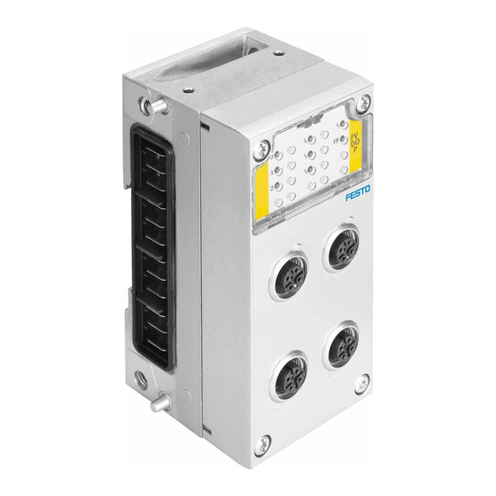
Page 35: System Overview Cpx-F8De-P
Interlinking block with contact rails, e.g. CPX-M-GE-EV Product labelling Electrical plug connector LEDs on the input module aJ Retaining screws Fig. 1/1: Design of the input module CPX-F8DE-P Use only metal interlinking blocks. • Festo CPX-F8DE-P-EN en 2005b English... -
Page 36: Components
– For the use of sensors with static 24 V DC power supply only – For the use of electronic sensors with current consumption up to 2 A – Degree of protection IP65 when using cover caps ISK-M12 for unused connections Festo CPX-F8DE-P-EN en 2005b English... - Page 37 – Degree of protection IP20 – Degree of protection IP65 with use of covering AK-8KL CPX-AB-ID-P Manifold block without connection technology – Coded identifier Tab. 1/1: Permissible manifold blocks Information on electrical connection and display elements è Chapter 2.2. Festo CPX-F8DE-P-EN en 2005b English...
- Page 38 – Short-circuit protection. Tab. 1/2: Electronics module Interlinking blocks An interlinking block establishes the mechanical and electrical connection to the CPX terminal. Note Malfunctions possible due to absent shielding. Use only metal interlinking blocks. • Festo CPX-F8DE-P-EN en 2005b English...
- Page 39 1. System overview CPX-F8DE-P Interlinking block Description CPX-M-GE-EV without system supply CPX-M-GE-EV-S-7/8-5POL with system supply, connection: 7/8'' (5-pin) CPX-M-GE-EV-S-7/8-CIP-4P with system supply, connection: 7/8'' (4-pin) CPX-M-GE-EV-S-PP-5POL with system supply, connection: push-pull (5-pin) Festo CPX-F8DE-P-EN en 2005b English...
- Page 40 Interlinking block Description CPX-M-GE-EV-S-M12-5POL with system supply, connection: M12 (5-pin) CPX-M-GE-EV-Z-7/8-5POL with additional supply, connection: 7/8” (5-pin) CPX-M-GE-EV-Z-PP-5POL with additional supply, connection: push-pull (5-pin) CPX-M-GE-EV-W-M12-5POL with voltage forwarding, connection: M12 (5-pin) Tab. 1/3: Permissible interlinking blocks Festo CPX-F8DE-P-EN en 2005b English...
- Page 41 CPX VTSA-FB-VI Valve terminal VTSA with modular VTSA-FB-NPT-VI electrical peripheral equipment CPX VTSA-F-FB-VI Valve terminal VTSA-F with modular VTSA-F-FB-NPT-VI electrical peripheral equipment CPX Tab. 1/5: Supported product versions in combination with the above bus nodes Festo CPX-F8DE-P-EN en 2005b English...
- Page 42 Valve terminal Valve types MPASFBVI MPA1, MPA2 on VMPA…FB-EMG-… VTSA-FB-VI All up to width of 52 mm VTSA-F-FBVI All up to width of 52 mm Tab. 1/6: Supported product versions of the CPX terminal 1-10 Festo CPX-F8DE-P-EN en 2005b English...
-
Page 43: Required Bus Topology (Control Chain)
(for safety controller) PROFIBUS or PROFINET IO Input module CPX-F8DE-P Embedded PROFIsafe data (black channel) Output module CPX-FVDA-P2 (example) PROFIBUS or PROFINET IO Fig. 1/2: Communication between safety controller and safety modules via PROFIsafe 1-11 Festo CPX-F8DE-P-EN en 2005b English... -
Page 44: Profisafe
PROFIsafe data module 3 bytes for F usage data to the module Embedded PROFIsafe telegram 1 byte status or control byte 3 bytes CRC signature (CRC2) Fig. 1/3: Telegram structure of the input module CPX-F8DE-P 1-12 Festo CPX-F8DE-P-EN en 2005b English... -
Page 45: Process Image (I/O Image)
2 bytes input data (F usage data, è Tab. 1/8) – – 1 status byte (for PROFIsafe communication) – 3 bytes CRC (for PROFIsafe communication). Function modes are set via the output data from the input module. 1-13 Festo CPX-F8DE-P-EN en 2005b English... -
Page 46: Bit Pattern Of The Output And Input Data (F Usage Data)
Function mode for channel pair 1/0 Tab. 1/7: Bit pattern for output data (F usage data, bytes 0, 1 and 2) Ensure that the data in the output image contain a valid • module configuration for your safety application. 1-14 Festo CPX-F8DE-P-EN en 2005b English... - Page 47 Byte Bit 7 Bit 6 Bit 5 Bit 4 Bit 3 Bit 2 Bit 1 Bit 0 Tab. 1/9: Input image; example for channel pairs E0/E1 and E2/E3 1-15 Festo CPX-F8DE-P-EN en 2005b English...
-
Page 48: Channel-Wise Passivation
The input module indicates via the input image the current channel error status to the control unit: – All input bits relating to the channel bundle = 0 – All qualification bits relating to the channel bundle = 0 1-16 Festo CPX-F8DE-P-EN en 2005b English... - Page 49 1) Bit in output image è Tab. 1/7 2) Bit in input image è Tab. 1/8, byte 1 X: Signal can be 0 or 1 Tab. 1/10: Sequence description of channel error acknowledgment – example 1-17 Festo CPX-F8DE-P-EN en 2005b English...
-
Page 50: Mode Of Operation Of The Input Module
– Overvoltage, undervoltage, overload, short circuit and cross circuit – PROFIsafe communication failure or malfunction – Failure or defect of individual safety-determining components of the input module. 1-18 Festo CPX-F8DE-P-EN en 2005b English... -
Page 51: Safe System Status
Use as an input module for a higher-order safety controller. Multiple input modules can be used together to monitor sensors independently. The following overview constitutes a selection and lists some but not all possible applications. 1-19 Festo CPX-F8DE-P-EN en 2005b English... - Page 52 Safety door 1oo2 T robust mechanical Mode selector switch, 1 of N mechanical, rotary indexing table electronic, OSSD Tool detection Identifier mechanical, electronic, OSSD Tab. 1/11: Possible applications with contact types and appropriate function modes 1-20 Festo CPX-F8DE-P-EN en 2005b English...
-
Page 53: Details Of The Function Modes
² Can be used with low safety requirements Tab. 1/12: Recommended sensors Note Some function modes may restrict the manifold blocks that can be selected. Make sure that the manifold block required for the • safety function is used. 1-21 Festo CPX-F8DE-P-EN en 2005b English... - Page 54 Make sure that the mode switching is implemented • within one PROFIsafe cycle. Otherwise there may a short-term switch to a different function mode, which may cause unexpected reactions. Take this into account in your application. 1-22 Festo CPX-F8DE-P-EN en 2005b English...
- Page 55 (T0, T2, T4, T6 static on) Signal evaluation of up to 2 independent single-channel switches/sensors (N/O or N/C) per channel pair. In this function mode, T0, T2, T4 and T6 are at static 24 V DC. 1-23 Festo CPX-F8DE-P-EN en 2005b English...
- Page 56 Functional safety – PL c, Cat. 1/SIL 1 with switch/sensor tried and tested in accordance with EN 13849-2, Table D.3, and with wiring protection of the customer application in accordance with EN 13849-2, Table D.4 1-24 Festo CPX-F8DE-P-EN en 2005b English...
- Page 57 – CPX-M-AB-4-M12X2-5POL-T – CPX-AB-8-KL-4POL. Note Safety requests cannot be evaluated by the safety control during the test period. Function mode 2 can be alternatively used to reset sensors with self-monitored electronic outputs. 1-25 Festo CPX-F8DE-P-EN en 2005b English...
- Page 58 2 single-channel switches/sensors (N/O or N/C) Circuit diagram Channel pair connections Tab. 1/16: Function mode 3 – 1oo1 T (example A) Note Safety evaluation only with the following manifold blocks: – CPX-M-AB-4-M12X2-5POL-T – CPX-AB-8-KL-4POL. 1-26 Festo CPX-F8DE-P-EN en 2005b English...
- Page 59 PL c, Cat. 3/SIL 2 with certified switch/sensor of suitable safety classification and with wiring protection of customer application in accordance with EN 13849-2, Table D.4, and with testing of the safety application once a year 1-27 Festo CPX-F8DE-P-EN en 2005b English...
- Page 60 Tab. 1/18: Function mode 4 – 1oo1 D This function mode tests the switch function and wiring of the sensors. Use only sensors with antivalent outputs in which the one • contact opens before the other contact closes. 1-28 Festo CPX-F8DE-P-EN en 2005b English...
- Page 61 EN 13849-2, Table D.3, the switches/sensors must be implemented as independent systems in the customer application – up to PL e, Cat. 3/SIL 3 with certified switches/sensors of an appropriate safety classification. 1-29 Festo CPX-F8DE-P-EN en 2005b English...
- Page 62 24 V 24 V 24 V 24 V T1/FE T3/FE T5/FE T7/FE FE contact of the sensor via the M12 plug screw connection on the module Tab. 1/20: Function mode 5 – 1oo2 (example B) 1-30 Festo CPX-F8DE-P-EN en 2005b English...
- Page 63 24 h – up to PL e, Cat. 4/SIL 3 with certified sensor (OSSD) of an appropriate safety classification and with wiring monitoring by the connected sensor (example B). 1-31 Festo CPX-F8DE-P-EN en 2005b English...
- Page 64 (e.g. emergency stop, certified switches/sensors). Note Safety evaluation only with the following manifold blocks: – CPX-M-AB-4-M12X2-5POL-T – CPX-AB-8-KL-4POL. Functional safety – up to PL e, Cat. 3/SIL 2 with certified switches/sensors of an appropriate safety classification 1-32 Festo CPX-F8DE-P-EN en 2005b English...
- Page 65 Note that a zero crossing is required before every actuation (both N/C standby contacts closed). Circuit diagram Channel pair connections Tab. 1/22: Function mode 7 – 1oo2 D 1-33 Festo CPX-F8DE-P-EN en 2005b English...
- Page 66 Signal evaluation of mechanical contacts on a two-channel switch/sensor (internally equivalent) or of 2 independent, tried and tested switches. Circuit diagram Channel pair connections Tab. 1/23: Function mode 8 – 1oo2T (robust) 1-34 Festo CPX-F8DE-P-EN en 2005b English...
- Page 67 PL e, Cat. 4/SIL 3 with certified switch/sensor of an appropriate safety classification or 2 independent tested switches in accordance with EN 13849-2, Table D.3, and with wiring protection in accordance with EN 13849-2, Table D.4. 1-35 Festo CPX-F8DE-P-EN en 2005b English...
- Page 68 9. The power supply can be optionally switched from T2 or 24 V to one of the inputs E2, E3, E4, E5. Required for this example: channel pairs E0/E1 and E6/E7 are not configured to function mode 9. 1-36 Festo CPX-F8DE-P-EN en 2005b English...
- Page 69 “1 of 2” circuits Mode 9 Mode 9 Mode 9 Mode 9 Tab. 1/25: Function mode 9 for up to 2 circuits Set the remaining channel pairs as desired – but not to • function mode 9. 1-37 Festo CPX-F8DE-P-EN en 2005b English...
- Page 70 (switch 8) to ON. Input image A 0 is always output in the input image instead of the parity bit so the set identifier in the safety control can always be used directly. 1-38 Festo CPX-F8DE-P-EN en 2005b English...
- Page 71 EN 13849-2 Table D.3 and with protection of the application against simple manipulation. Manifold block CPX-AB-ID-P meets these requirements for functional safety without any supplementary measures. 1-39 Festo CPX-F8DE-P-EN en 2005b English...
- Page 72 The input module reports module error 02: “Short circuit 0 V at clock signal output T1357”. Connect the FE contact of a sensor only to the M12 plug • screw connection of the module. 1-40 Festo CPX-F8DE-P-EN en 2005b English...
- Page 73 0 or 1 (depending on the function mode and input signal) error Tab. 1/27: Behaviour of input data with channel bundles If channel-wise passivation is not enabled, all input data bits are set to 0 if an error is detected. 1-41 Festo CPX-F8DE-P-EN en 2005b English...
- Page 74 – two-hand control device for starting a function – emergency stop switch for incidents – mode selector switch with 4 positions. Mode 7 Mode 9 Mode 6 Mode 9 Fig. 1/4: Maximum configuration 1-42 Festo CPX-F8DE-P-EN en 2005b English...
- Page 75 E2/E3 Evaluation of the emergency stop button E4/E5 Evaluation of a mode selector switch E6/E7 Note The safety-related evaluation in this example is only possible with the following manifold blocks: – CPX-M-AB-4-M12X2-5POL-T – CPX-AB-8-KL-4POL. 1-43 Festo CPX-F8DE-P-EN en 2005b English...
- Page 76 The other channel pairs on the input module can be used to evaluate other sensors on a loading and an unloading station. When connecting the sensors (e.g. SMT-8M-A) it is advisable to use pre-assembled Y cables from the NEBU modular cable system è www.festo.com/catalogue. 1-44 Festo CPX-F8DE-P-EN en 2005b English...
- Page 77 This involves the channel pairs being set with the following function modes: Channel pair Mode Comments E0/E1 Evaluation of 4 positions of the rotary indexing table. E2/E3 This application example can also be implemented using electronic sensors (2-wire or 3-wire sensors). 1-45 Festo CPX-F8DE-P-EN en 2005b English...
- Page 78 Safety evaluation only with the following manifold blocks: – CPX-M-AB-4-M12X2-5POL-T – CPX-AB-8-KL-4POL. Antivalence is evaluated in order to diagnose the sensor wiring. Reaching the end position is output as secured logical information in the PAE (input image). 1-46 Festo CPX-F8DE-P-EN en 2005b English...
- Page 79 2 A – CPX-M-AB-4-M12X2-5POL-T up to 0.7 A. When wired in a control cabinet, the input module can also be operated with manifold block CPX-AB8-KL-4POL. All signals are available there without any restriction. 1-47 Festo CPX-F8DE-P-EN en 2005b English...
- Page 80 The safety-related evaluation in this example is only possible on the following manifold blocks: – CPX-M-AB-4-M12X2-5POL-T – CPX-AB-8-KL-4POL. When using manifold block CPX-AB-8-KL-4POL (“CageClamp” connection technology), another sensor/switch can be connected to the channel pair via terminals 24 V and E1. 1-48 Festo CPX-F8DE-P-EN en 2005b English...
- Page 81 1.4.7 2 safety doors on one channel pair This application example shows the circuitry of two safety doors on one channel pair. Mode 4 Fig. 1/9: 2 safety door sensors on one channel pair 1-49 Festo CPX-F8DE-P-EN en 2005b English...
- Page 82 8. This safety function is enabled only if both switches are closed within 60 seconds of each another. If a switch was not previously opened, the channel or the module is passivated. The input module reports channel error 55: “process value”. 1-50 Festo CPX-F8DE-P-EN en 2005b English...
- Page 83 Installation Chapter 2 Installation Festo CPX-F8DE-P-EN en 2005b English...
- Page 84 ......... . . 2-13 2.5.1 Ensuring the degree of protection ......2-14 Festo CPX-F8DE-P-EN en 2005b English...
-
Page 85: Installation
U and U EL/SEN Protection from electric shock (protection from direct and indirect contact) in accordance with IEC 60204-1 (Electrical equipment of machines, General requirements) is guaranteed with the use of PELV circuits. Festo CPX-F8DE-P-EN en 2005b English... -
Page 86: Module-Related Rules For Configuration
Only operate input module with one of the following • manifold blocks: – CPX‐M-AB-4-M12X2- 5POL-T – CPX‐M-AB-4-M12X2- 5POL – CPX-AB-8-KL-4POL – CPX-AB-ID-P. Only use input module in conjunction with permitted • product versions of the CPX terminal è Chapter 1.1.3. Festo CPX-F8DE-P-EN en 2005b English... -
Page 87: Electrical Connection And Display Elements
Module error LED (red) FP-LED (green) – fail-safe mode Module identifier F8DIP (for CPX-F8DE-P) Area for electrical connections (here CPX-AB-8-KL-4POL) Fig. 2/1: Display and connecting elements CPX-F8DE-P Detailed information about the LEDs è Chapter 5.3. Festo CPX-F8DE-P-EN en 2005b English... -
Page 88: Pin Allocation On The Manifold Block Cpx-M-Ab-4-M12X2-5Pol-T
1) Never connect functional earth (FE) with pin 5 with this connection technology. The metal thread on the manifold block is used as the functional earth for connected sensors. Tab. 2/1: Pin allocation with M12 manifold block CPX-M-AB-4-M12X2-5POL-T Festo CPX-F8DE-P-EN en 2005b English... -
Page 89: Pin Allocation On The Manifold Block Cpx-M-Ab-4-M12X2-5Pol
FE = functional earth n.c. = free (not connected) Tab. 2/1: Pin allocation with M12 manifold block CPX-M-AB-4-M12X2-5POL The metal thread of the manifold block CPX-M-AB-4-M12X2- 5POL is internally connected to pin 5 (functional earth FE). Festo CPX-F8DE-P-EN en 2005b English... -
Page 90: Pin Allocation On The Manifold Block Cpx-Ab-8-Kl-4Pol
3: FE 0: T2 0: T6 1: T3 1: T7 2: I3 2: I7 3: FE 3: FE FE = functional earth n.c. = free (not connected) Tab. 2/2: Pin allocation with terminal strip manifold block Festo CPX-F8DE-P-EN en 2005b English... -
Page 91: Installation Of The Electronics Module
Changing the DIL switch setting è Chapter 2.4, Setting – the PROFIsafe address – Replacement of a defective electronics module. The plugs connected to the manifold block can remain attached while disassembling the manifold block. Festo CPX-F8DE-P-EN en 2005b English... -
Page 92: Disassembling The Electronics Module
2. Align manifold block 1, 2 or 3 and fit to electronics module 4. 3. Screw the retaining screws aJ into the existing threads. 4. Tighten retaining screws crosswise. Tightening torque: 0.9 … 1.1 Nm. 2-10 Festo CPX-F8DE-P-EN en 2005b English... -
Page 93: Setting The Profisafe Address
2 + 64 + 512 = 578 Decimal value when set to ON Calculation example – DIL switch 2, 7 and 0 (10) set ON Fig. 2/2: 10x DIL switch for setting the PROFIsafe address – binary coded 2-11 Festo CPX-F8DE-P-EN en 2005b English... - Page 94 2. Remove the manifold block è Chapter2.3.1. 3. Set PROFIsafe address on binary coded 10x DIL switch è Fig. 2/2. Permitted PROFIsafe addresses: 1 … 1022 4. Reinstall the manifold block è Chapter 2.3.2. 5. Switch input module on again. 2-12 Festo CPX-F8DE-P-EN en 2005b English...
-
Page 95: Connection Of Sensors
Cross-circuit monitoring of sensor wiring depends on the è Chapter 1.3.3). function mode being used Ensure that cross circuits in power circuits with voltages • above the maximum input voltage are not possible using appropriate installation measures. 2-13 Festo CPX-F8DE-P-EN en 2005b English... -
Page 96: Ensuring The Degree Of Protection
Use connection hardware with the required degree of • protection. Use cover caps to seal unused M12 connections. • Close terminal strip of manifold block CPX-AB-8-KL-4POL • with cover AK8KL. Accessories è www.festo.com/catalogue 2-14 Festo CPX-F8DE-P-EN en 2005b English... - Page 97 Commissioning Chapter 3 Commissioning Festo CPX-F8DE-P-EN en 2005b English...
- Page 98 ........3-16 Festo CPX-F8DE-P-EN en 2005b English...
- Page 99 CPX20200210.xml dated 10.02.2020 1) Revision code è Bus node product labelling Tab. 3/1: Required versions The configuration depends on the control system. The basic approach and required configuration data are presented in the following pages. Festo CPX-F8DE-P-EN en 2005b English...
-
Page 100: Commissioning
Reference source current versions of the GSDML/GSD files for CPX terminals are available on the Festo website è www.festo.com/sp. After importing the GSDML/GSD file into the project of the F-host configuration program, you can select and edit the CPX terminal with the input module CPX-F8DE-P in the configuration program. -
Page 101: Preparing For Commissioning
3. Dismantle the manifold block of the input module è Chapter 2.3.1. 4. Check the input module is in good condition. 5. Set the PROFIsafe address on the input module with DIL switches and install the manifold block è Chapter 2.3.2. Festo CPX-F8DE-P-EN en 2005b English... -
Page 102: Commissioning Steps
Set PROFIsafe parameters on the input module è Chapter 3.6. 3. Create and load the safety program. 4. Commission CPX terminal on field bus (PROFIBUS or PROFINET IO) and validate its behaviour in the test run. Festo CPX-F8DE-P-EN en 2005b English... -
Page 103: Setting The Profisafe Parameters
F_iPar_CRC value has been provide individual device (cannot be extended by 4 bytes. The parameters. altered) parameter F_Block_ID has the value 1 if the parameter F_iPar_CRC is present, otherwise it has the value 0. Festo CPX-F8DE-P-EN en 2005b English... - Page 104 F_iPar_CRC CRC via the individual device – CPX-F8DE-P does not – 0 parameters (iParameters). provide individual device (cannot be parameters. altered) Tab. 3/3: PROFIsafe parameters Festo CPX-F8DE-P-EN en 2005b English...
-
Page 105: Reading Out The Cpx Module Parameters
0, 1 Position of 10x DIL switch for the PROFIsafe address of the module, bits 8 and 9 1) Parameters read-only via operator unit and command interpreter (CI). Tab. 3/4: Overview – module parameters CPX-F8DE-P Festo CPX-F8DE-P-EN en 2005b English... - Page 106 0: switch element is set to OFF 1: switch element is set to ON Comment This parameter can only be changed by changing the DIL switch setting (read only). Tab. 3/5: DIL switch setting 3-10 Festo CPX-F8DE-P-EN en 2005b English...
-
Page 107: Parameter And Signal Display With The Operator Unit Cpx-Mmi-1
Module identifier in main menu Module identifier in the header of the (here at position 1) system submenu for a module Fig. 3/1: Module identifier of the input module CPX-F8DE-P on the operator unit 3-11 Festo CPX-F8DE-P-EN en 2005b English... - Page 108 8 input channels and the related qualification bits (Qualifiers) are displayed in accordance with the set function modes. The display of input signals and qualification bits corresponds here to the PROFIsafe process image. 3-12 Festo CPX-F8DE-P-EN en 2005b English...
-
Page 109: Configuration With Siemens Step 7 (Example)
4. Set the required starting addresses for inputs and outputsè Fig. 3/3. “Parameters” 5. Set default parameters on the input module. In online mode the PROFIsafe addresses of the DIL switch settings are displayed here. 3-13 Festo CPX-F8DE-P-EN en 2005b English... - Page 110 Input module CPX-F8DE-P in the configuration table of the CPX terminal Start addresses of the input module for inputs and outputs (here 1) Fig. 3/3: CPX terminal configuration with Siemens STEP 7 – HW Config 3-14 Festo CPX-F8DE-P-EN en 2005b English...
- Page 111 DIL switch è Fig. 2/2. Fig. 3/4: PROFIsafe parameters In this tab you have access to the PROFIsafe parameters of the input module. You can find detailed information on the individual parameters in Chapter 3.6. 3-15 Festo CPX-F8DE-P-EN en 2005b English...
- Page 112 Output module CPX-FVDA-P2 Unusable range (1 byte each for Pneumatic interface status/control and 3 bytes for CRC) MPA pneumatics Bus node CPX-FB13 Input module with 8 digital inputs and diagnostics Fig. 3/5: Addressing example 3-16 Festo CPX-F8DE-P-EN en 2005b English...
- Page 113 9 ... 14 9 ... 14 CPX-FVDA-P2 MPA: pneumatic interface – – MPA: pneumatic module – VMPA1FBEMG8 [8DO] MPA: pneumatic module – VMPA2FBEMG4 [4DO] Input and output addresses for the example è Fig. 3/5 Tab. 3/6: 3-17 Festo CPX-F8DE-P-EN en 2005b English...
- Page 114 3. Commissioning 3-18 Festo CPX-F8DE-P-EN en 2005b English...
- Page 115 Operation Chapter 4 Operation Festo CPX-F8DE-P-EN en 2005b English...
- Page 116 Normal operating status ........Festo CPX-F8DE-P-EN en 2005b English...
- Page 117 The designations of the LEDs correspond to the physical contacts E0 to E7. Note the special position of the input signals in the input • image of the CPX-F8DE-P è Chapter 1.2.3. Detailed information on error characteristics can be found in chapter 5.3.1. Festo CPX-F8DE-P-EN en 2005b English...
- Page 118 Channel error detected at input. signal PROFIsafe communication running. Operator Acknowledge Requested flashes quickly 1) Refers to the input channel to which the relevant status LED is assigned. 2) Input image based on calculation of operating mode. Festo CPX-F8DE-P-EN en 2005b English...
- Page 119 Possible causes of the error: – Module error – Undervoltage – Overvoltage – Overtemperature – Channel error with module passivation. Application running, PROFIsafe parameters not present. Self-test error flashes quickly Tab. 4/2: Normal operating status Festo CPX-F8DE-P-EN en 2005b English...
- Page 120 4. Operation Festo CPX-F8DE-P-EN en 2005b English...
- Page 121 Diagnostics and error handling Chapter 5 Diagnostics and error handling Festo CPX-F8DE-P-EN en 2005b English...
- Page 122 ........5-13 5.4.1 Diagnostics with the operator unit CPX-MMI ....5-13 Festo CPX-F8DE-P-EN en 2005b English...
-
Page 123: Diagnostics And Error Handling
Information about the diagnostic options on the complete CPX terminal and/or all modules can be found in the CPX system description and/or in the description of the bus node. Note Ensure that the diagnostic messages cannot be evaluated for safety-related measures. Festo CPX-F8DE-P-EN en 2005b English... -
Page 124: Error Characteristics
– – – – – – ü ü ü ü ü ü ü ü ü ü ü Module error overvoltage ü ü ü ü ü ü ü ü ü ü ü Module error F_DEST_ADD different Festo CPX-F8DE-P-EN en 2005b English... - Page 125 Module error overtemperature ü ü ü ü ü ü ü ü ü ü ü Channel error channel function ü ü ü ü ü ü ü ü ü ü ü Module error in self-test Tab. 5/2: Error messages Festo CPX-F8DE-P-EN en 2005b English...
-
Page 126: Diagnostics Using Leds
In the normal operating status, the following LEDs light up: FP-LED 2 – Status LEDs 4 of the active input channels – The status LEDs on inactive input channels and the module error LEDs 1 and channel error LEDs 3 do not light. Festo CPX-F8DE-P-EN en 2005b English... - Page 127 3. Reintegrate input module LED on – Overtemperature – Absence of safety parameterisation – Defective safety communication – Channel error during “module-based passivation” configuration 1) If self-test errors reoccur: replace input module. Tab. 5/3: Module error LED Festo CPX-F8DE-P-EN en 2005b English...
- Page 128 – A clock signal is pending – at the input. LED flashes 1x briefly out 1)The status LED follows the signal pending at the input channel. Tab. 5/5: Status LED Festo CPX-F8DE-P-EN en 2005b English...
- Page 129 – Input module communicates with an F-Host via a PROFIsafe protocol. illuminated – Input module is in a safe – shut-down condition LED is off Tab. 5/6: FP LED After remedial action, reintegrate the input module. • Festo CPX-F8DE-P-EN en 2005b English...
-
Page 130: Behaviour In Response To Original Module Errors
Replace input module • Tab. 5/7: Behaviour in response to module errors All input channels on the input module are passivated in response to module errors. After remedial action: reintegrate the input module. • 5-10 Festo CPX-F8DE-P-EN en 2005b English... -
Page 131: Behaviour In Response To Channel Errors
– Unauthorised logical value – Incorrect manifold block Check sensors and • installed wiring – FE connected to T1, T3, T5 or T7 – Loose contact on two-channel sensors 5-11 Festo CPX-F8DE-P-EN en 2005b English... - Page 132 – Loose contact, module input signal fails 1) Module error LED lights while 'channel-based passivation' is disabled. Tab. 5/8: Behaviour in response to channel errors After remedial action: always reintegrate the input • module. 5-12 Festo CPX-F8DE-P-EN en 2005b English...
-
Page 133: Diagnostics Via The Bus Node
(in this case, module 1) Current module errors (in this case, none) Fig. 5/2: Module identifier of the input module CPX-F8DE-P on the operator unit Furthermore, the operator unit offers access to the diagnostic memory è Description P.BE-CPX-MMI-1-... 5-13 Festo CPX-F8DE-P-EN en 2005b English... - Page 134 5. Diagnostics and error handling 5-14 Festo CPX-F8DE-P-EN en 2005b English...
- Page 135 Service, repair, disposal Chapter 6 Service, repair, disposal Festo CPX-F8DE-P-EN en 2005b English...
- Page 136 ............Festo CPX-F8DE-P-EN en 2005b English...
- Page 137 Always replace the input module if there is an internal • fault. Send the unmodified defective input module, including • a description of the error and the application, back to Festo for analysis. Disassembly and assembly of the electronics module è Section 2.3. Festo CPX-F8DE-P-EN en 2005b English...
- Page 138 6. Service, repair, disposal Disposal The material used in the packaging has been specifically chosen for its recyclability. For final disposal of the input module, please contact a certified waste disposal business for electronic (WEE) scrap. Festo CPX-F8DE-P-EN en 2005b English...
- Page 139 Technical appendix Appendix A Technical appendix Festo CPX-F8DE-P-EN en 2005b English...
- Page 140 Technical data of the manifold blocks ....... Festo CPX-F8DE-P-EN en 2005b English...
-
Page 141: Technical Appendix
1) Characteristic value if the application is tested within 24 hours: to PL e Cat. 3, SIL 3, SIL CL 3 1) Characteristic value if the application is tested within 24 h: DC = 94 % 3) Characteristic value if the application is tested within 24 h: SFF = 95 % Festo CPX-F8DE-P-EN en 2005b English... -
Page 142: Safety Characteristics
EC type test certificate. CE marking è Declaration of conformity in accordance with EU Machinery Directive è www.festo.com/sp 2006/42/EC according to EU-EMC directive 2004/108/EC Certificate issuing authority 01/205/5444.00/15 Tab. A/1: Safety characteristics Festo CPX-F8DE-P-EN en 2005b English... -
Page 143: Characteristic Values Of The Input Module
Max. load current per clock line T0, T2, T4, T6 Max. resultant current at T1, T3, T5, T7 Max. output current at 24 V terminals Max. residual current per input module Cable lengths to sensor – Cable type LiFY11Y-OB, unshielded, 3 x 0.14 mm² Festo CPX-F8DE-P-EN en 2005b English... - Page 144 Compatible with fast start-up (FSU) 2 Time for switch-on phase until input module is ready (start-up) Max. tolerance time until – – – 0.5 10 0.5 0.5 10 diagnostic message of channel fault Tab. A/4: Module characteristic values Festo CPX-F8DE-P-EN en 2005b English...
- Page 145 Dependent on the manifold block Electromagnetic compatibility (EMC) Declaration of Conformity èwww.festo.com/sp – Immunity to interference and emitted interference UL certification c UL us - Recognized (OL) 1) è Appendix A.2 Tab. A/5: Ambient characteristics Festo CPX-F8DE-P-EN en 2005b English...
-
Page 146: Technical Data Of The Manifold Blocks
Die-cast aluminium materials Connections – Design 4 sockets M12, metal thread, 5-pin – Contact load 1) Degree of protection is achieved with the permitted combination with interlinking block and connectors. Tab. A/7: Technical data CPX-M-AB-4-M12X2-5POL Festo CPX-F8DE-P-EN en 2005b English... - Page 147 Degree of protection in IP65, completely installed accordance with EN 60 529 Information about housing Reinforced polyamide, polycarbonate materials 1) Degree of protection is achieved with the permitted combination with interlinking block. Tab. A/9: Technical data CPX-AB-ID-P Festo CPX-F8DE-P-EN en 2005b English...
- Page 148 A. Technical appendix A-10 Festo CPX-F8DE-P-EN en 2005b English...
- Page 149 Index Appendix B Index Festo CPX-F8DE-P-EN en 2005b English...
- Page 150 ..........Festo CPX-F8DE-P-EN en 2005b English...
- Page 151 ........Festo CPX-F8DE-P-EN en 2005b English...
- Page 152 GSD/GSDML file ........Festo CPX-F8DE-P-EN en 2005b English...
- Page 153 ........1-14 Festo CPX-F8DE-P-EN en 2005b English...
- Page 154 ........Festo CPX-F8DE-P-EN en 2005b English...
- Page 155 ......XXIII Transport and storage conditions ....Festo CPX-F8DE-P-EN en 2005b English...
- Page 156 User information ....... . XXII Festo CPX-F8DE-P-EN en 2005b English...
Need help?
Do you have a question about the CPX Series and is the answer not in the manual?
Questions and answers