
Related Manuals for Moxa Technologies MiiNePort E2-H


Summary of Contents for Moxa Technologies MiiNePort E2-H
- Page 1 MiiNePort E2/E3 User’s Manual Edition 9.1, November 2017 www.moxa.com/product © 2017 Moxa Inc. All rights reserved.
- Page 2 MiiNePort E2/E3 User’s Manual The software described in this manual is furnished under a license agreement and may be used only in accordance with the terms of that agreement. Copyright Notice © 2017 Moxa Inc. All rights reserved. Trademarks The MOXA logo is a registered trademark of Moxa Inc. All other trademarks or registered marks in this manual belong to their respective manufacturers.
-
Page 3: Table Of Contents
Table of Contents Introduction ............................1-1 Overview ............................1-2 Package Checklist ..........................1-2 Product Features ..........................1-3 Module Dimensions ..........................1-5 Panel Layout and Pin Assignments ......................1-7 Evaluation Board Layout ....................... 1-7 Pin Assignments .......................... 1-8 LED Indicators ..........................1-11 Getting Started.......................... - Page 4 Console Settings ........................7-30 Firmware Upgrade ........................7-30 Configuration Tools ........................7-31 Change Password ........................7-32 NetEZ Technologies ........................... 8-1 EZPower ............................8-2 SCM (Serial Command Mode) ....................... 8-2 AutoCFG (Auto Configuration) ......................8-3 MCSC (Multiple Channel Serial Communication) ..................8-4 Command Packets ........................
-
Page 5: Introduction
Introduction The MiiNePort series of embedded device servers is compact drop-in modules that can be integrated with your serial devices to enable connectivity to an Ethernet network. All MiiNePort Series modules come equipped with built-in TCP/IP protocols and other easy-to-use network enabling tools for fast integration, allowing you to provide network access to any electronic device that has a serial port. -
Page 6: Overview
MiiNePort E2: 0 to 55°C operating temp., 50 bps to 230.4 Kbps baudrate • MiiNePort E2-H: 0 to 55°C operating temp., 50 bps to 921.6 Kbps baudrate • MiiNePort E2-T: -40 to 85°C operating temp., 50 bps to 230.4 Kbps baudrate MiiNePort E2-H-T: -40 to 85°C operating temp., 50 bps to 921.6 Kbps baudrate... -
Page 7: Product Features
MiiNePort E2/E3 Introduction Product Features All MiiNePort E2/E3 Series modules have the following general features: • MiiNePort NetEZ Technology makes integration incredibly easy • Moxa’s second generation MiiNe SOC optimizes reliability • A versatile choice of operation modes to meet application needs •... - Page 8 MiiNePort E2/E3 Introduction EZPage: Do you eed a module that allows direct communication with the attached serial device? Use the MiiNePort E2/E3’s EZPage with Java Applet to create a visual web page for configuring and communicating with the attached serial device. AutoCFG (Auto Configuration) saves time and effort when setting up the MiiNePort E2/E3 one by one during the device production process.
-
Page 9: Module Dimensions
MiiNePort E2/E3 Introduction MCSC (Multiple Channel Serial Communication) provides dual connections and dual channels so your device can act as a server and client at the same time. Module Dimensions MiiNePort E2 units: mm (in) - Page 10 MiiNePort E2/E3 Introduction MiiNePort E3 units: mm (in)
-
Page 11: Panel Layout And Pin Assignments
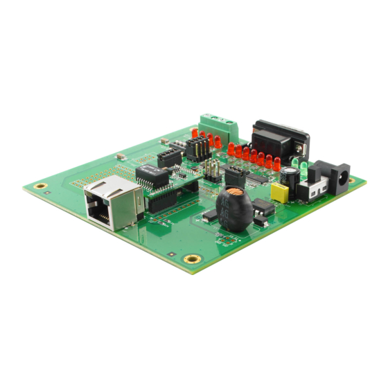
MiiNePort E2/E3 Introduction Panel Layout and Pin Assignments Evaluation Board Layout MiiNePort E2 Ethernet RJ45 Connector MiiNePort E2 Module Location Serial Interface Jumper Power Switch Power Jack Power & Ready LED DB9 Male Connector Serial Port Status LED Digital IO Terminal Block Digital Output LED Digital Input/Output Mode Digital Input Switch... -
Page 12: Pin Assignments
MiiNePort E2/E3 Introduction Pin Assignments MiiNePort E2 Module Pin Assignment Bottom Panel of the MiiNePort E2 Module Signal Name Function Ethernet Tx+ Ethernet Transmit Data+ Ethernet Tx- Ethernet Transmit Data- Ethernet Rx+ Ethernet Receive Data+ Ethernet Rx- Ethernet Receive Data- Signal Name Function 100M LED... - Page 13 MiiNePort E2/E3 Introduction MiiNePort E3 Module Pin Assignment Ethernet Pins (JP2) Signal Name Function Reserve Reserve Reserve Reserve PoE signal pair 1 PoE power from Tx signal PoE spare pair 1 PoE power from RJ45 4, 5 pin PoE signal pair 2 PoE power from Rx signal PoE spare pair 2 PoE power from RJ45 7, 8 pin...
- Page 14 MiiNePort E2/E3 Introduction Evaluation Board Ethernet Port Pin Assignment RJ45 Signal Evaluation Board Serial Port Pin Assignment DB9 Male RS-232 RS-485-2W – – – – – – – 1-10...
-
Page 15: Led Indicators
MiiNePort E2/E3 Introduction LED Indicators MiiNePort Evaluation Board LED Name Color Description Power 1. Power is off 2. A power error condition exists 3. System error Green, Steady On Indicates that the power is on. Ready Green, Blinking every 1 1. -
Page 16: Getting Started
Getting Started This chapter includes information about how to install MiiNePort Series modules for development and testing. The following topics are covered in this chapter: Wiring Precautions Installing the MiiNePort module onto the MiiNePort Evaluation Board Selecting the Serial Interface ... -
Page 17: Wiring Precautions
MiiNePort E2/E3 Getting Started Wiring Precautions This section describes some important safety precautions that you should pay attention to before proceeding with any installation. ATTENTION Be sure to disconnect the power cord before installing or wiring the evaluation board. ATTENTION Determine the maximum possible current in each power wire and common wire. -
Page 18: Installing The Miineport Module Onto The Miineport Evaluation Board
MiiNePort E2/E3 Getting Started Installing the MiiNePort module onto the MiiNePort Evaluation Board MiiNePort E2 Before using the MiiNePort evaluation board with the module, be sure to disconnect the power supply, network, and serial device. A profile of the MiiNePort is shown in the center of the evaluation board near the top. -
Page 19: Connecting The Power
MiiNePort E2/E3 Getting Started Connecting the Power Connect the 12-48 VDC power line with the evaluation board’s power jack. If the power is properly supplied, the power LED on the evaluation board (D14) will show a solid green color until the system is ready. When the system is ready, the ready LED on the module will show a solid green color. -
Page 20: Digital I/O Channel Settings
MiiNePort E2/E3 Getting Started Digital I/O Channel Settings Each module has four digital I/O (DIO) channels. (Refer to the Pin Assignment section in Chapter 1 for the module’s configurable DIO pin descriptions. Refer to the Evaluation Board Layout section in Chapter 1 to select corresponding settings on the evaluation board.) All four DIO channels can be configured by software. -
Page 21: Choosing The Proper Operation Mode
Choosing the Proper Operation Mode The MiiNePort modules support operation modes for COM mapping and TCP/IP. After choosing the proper operation mode for your application, refer to subsequent chapters for configuration details. The following topics are covered in this chapter: ... -
Page 22: Overview
MiiNePort E2/E3 Choosing the Proper Operation Mode Overview The MiiNePort acts as a bridge for connecting serial devices to Ethernet networks. After choosing the best operation mode for your application, you can use your computer to access, manage, and configure your serial devices from anywhere in the world over the Internet. -
Page 23: Tcp Client Mode
MiiNePort E2/E3 Choosing the Proper Operation Mode 1. The host connects to the module configured for TCP Server mode. 2. Once the connection is established, data can be transmitted in both directions—from the host to the module, and from the module to the host. TCP Client Mode In TCP Client mode, the module can actively establish a TCP connection to a predefined host computer when serial data arrives. -
Page 24: Rfc2217 Mode
MiiNePort E2/E3 Choosing the Proper Operation Mode RFC2217 Mode RFC2217 is an industrial public protocol for sharing serial devices over TCP/IP Ethernet networks. RFC2217 is similar to Moxa’s proprietary Real COM mode in that it allows users to continue using software that was written for pure serial communications applications. -
Page 25: Ethernet Modem Mode
MiiNePort E2/E3 Choosing the Proper Operation Mode ATTENTION The Real COM driver comes with NPort Windows Driver Manager, which is included on the CD-ROM shipped with the MiiNePort Starter kit. ATTENTION Real COM mode allows several hosts to simultaneously access to the MiiNePort module. The driver controls host access to attached serial devices by checking the host’s IP address against the Accessible IP list. -
Page 26: Choosing The Configuration Tool
Choosing the Configuration Tool The MiiNePort supports several tools for configuring the module. In this chapter, we briefly describe the options available and appropriate situations for using those options. The following topics are covered in this chapter: Utility Console ... -
Page 27: Utility Console
MiiNePort E2/E3 Choosing the Configuration Tool Utility Console Device Search Utility You can find the Device Search Utility on the CD-ROM that came with your product. NPort Search Utility is designed for Windows and is mainly used to search for the MiiNePort modules and for assigning IP addresses. Refer to the Web Console for additional configuration information. -
Page 28: Telnet Console
MiiNePort E2/E3 Choosing the Configuration Tool Telnet Console Your MiiNePort can be configured over the network with Telnet, which requires that the module has a network connection and an IP address. We briefly discuss Telnet console configuration in Chapter 5: Initial IP Address Configuration. -
Page 29: Initial Ip Address Configuration
Initial IP Address Configuration When setting up your MiiNePort module for the first time, the first thing you should do is configure the IP address. This chapter introduces the methods that can be used to configure the module’s IP address. For more details about network settings, refer to the Network Settings section in Chapter 7: Web Console Configuration. -
Page 30: Static Vs. Dynamic Ip Address
MiiNePort E2/E3 Initial IP Address Configuration Static vs. Dynamic IP Address You should first determine whether the module will be assigned a Static IP or Dynamic IP (either DHCP or BOOTP application). • If the module is used in a Static IP environment, you need to configure the IP address directly. •... -
Page 31: Telnet Console
MiiNePort E2/E3 Initial IP Address Configuration After issuing this command, a Connect failed message will appear. After the module reboots, its IP address will be updated to the new address, and you can reconnect the module using the utility, web, or Telnet console to verify that the update was successful. - Page 32 MiiNePort E2/E3 Initial IP Address Configuration 4. Select IP address by pressing 1 and then press Enter. 5. Use the backspace key to erase the current IP address. Type in the new IP address and then press Enter.
- Page 33 MiiNePort E2/E3 Initial IP Address Configuration 6. Press any key to continue. 7. Press M and then Enter to return to the main menu.
- Page 34 MiiNePort E2/E3 Initial IP Address Configuration 8. Press S and then Enter to Save/Restart the system. 9. Press Y and then Enter to save the new IP address and restart the module.
-
Page 35: Utility Console And Driver Installation
Utility Console and Driver Installation This chapter teaches you how to install the MiiNePort’s utilities, use the utilities to perform simple configurations, and install the drivers. The following topics are covered in this chapter: Device Search Utility (DSU) Installing the Device Search Utility ... -
Page 36: Device Search Utility (Dsu)
MiiNePort E2/E3 Utility Console and Driver Installation Device Search Utility (DSU) Installing the Device Search Utility 1. Click the INSTALL UTILITY button in the MiiNePort Installation CD to install the Device Search Utility. Once the program starts running, click Yes to proceed. 2. - Page 37 MiiNePort E2/E3 Utility Console and Driver Installation 4. Select the additional tasks you would like to set up to be performed while installing the DSU; then, click Next. 5. The installer will display a summary of the installation options. Click Install to begin the installation. The setup window will report the progress of the installation.
-
Page 38: Device Search Utility Configuration
MiiNePort E2/E3 Utility Console and Driver Installation 6. Click Finish to complete the installation of the Device Search Utility. Device Search Utility Configuration The Broadcast Search function is used to locate all MiiNePort modules that are connected to the same LAN as your computer. -
Page 39: Nport Windows Driver Manager
MiiNePort E2/E3 Utility Console and Driver Installation 3. When the search is complete, all MiiNePort modules that were located will be displayed in the Device Search Utility window. 4. To modify the configuration of the highlighted MiiNePort, click the Console icon to open the web console. This will take you to the web console, where you can make configuration changes. - Page 40 MiiNePort E2/E3 Utility Console and Driver Installation 3. Click Browse to select the destination directory and then click Next to install program files to the directory displayed in the input box. 4. Click Next to install the program’s shortcuts in the appropriate Start Menu folder. 5.
-
Page 41: Using Nport Windows Driver Manager
MiiNePort E2/E3 Utility Console and Driver Installation 6. Click Finish to complete the installation of NPort Windows Driver Manager. Using NPort Windows Driver Manager After you have installed the NPort Windows Driver Manager, you can set up the MiiNePort’s serial port, which is connected to your device’s main board, as remote COM ports for your PC host. - Page 42 MiiNePort E2/E3 Utility Console and Driver Installation 3. Click Search to search for the MiiNePort modules. From the list that is generated, select the server to which you will map COM ports, and then click OK. 4. Alternatively, you can select Input Manually and then manually enter the MiiNePort module’s IP Address, 1st Data Port, 1st Command Port, and Total Ports to which COM ports will be mapped.
- Page 43 MiiNePort E2/E3 Utility Console and Driver Installation 5. COM ports and their mappings will appear in blue until they are activated. Activating the COM ports saves the information in the host system registry and makes the COM port available for use. The host computer will not have the ability to use the COM port until the COM ports are activated.
-
Page 44: Command Line Installation/Removal
MiiNePort E2/E3 Utility Console and Driver Installation Command Line Installation/Removal The NPort Windows Driver Manager v1.19 and above comes with a command-line script tool – npcli.exe for installation, removal of the driver, and configuring NPort driver functions. After successfully installing the NPort Windows Driver Manager v1.19 (or above), the default file path is C:\Program Files\NPortDrvManager as shown below. - Page 45 MiiNePort E2/E3 Utility Console and Driver Installation The usage instructions will show up for user’s reference. ------------------------------------------------------------------------------ NPort Command-Line Interface Ver2.0 Build 16052400 ------------------------------------------------------------------------------ Usage: 1. NPort Driver operation: npcli /driver [/install | /uninstall | /upgrade] [PATH_NAME] /install Install specified driver to host. /uninstall Uninstall current installed driver from host.
-
Page 46: The Linux Real Tty Driver
MiiNePort E2/E3 Utility Console and Driver Installation /password moxa npcli /device /apply 1 Note: Npcli.exe requires an administrator privilege to change device settings. It support only IPv4 and it must be run under Windows XP and later versions. The Linux Real TTY Driver 1. -
Page 47: Removing Mapped Tty Ports
MiiNePort E2/E3 Utility Console and Driver Installation Mapping tty ports manually To map tty ports manually, execute mxaddsvr and manually specify the data and command ports, as in the following example: # cd /usr/lib/npreal2/driver # ./mxaddsvr 192.168.3.4 16 4001 966 In this example, 16 tty ports will be added, all with IP 192.168.3.4, with data ports from 4001 to 4016 and command ports from 966 to 981. -
Page 48: Configuring The Unix Driver
MiiNePort E2/E3 Utility Console and Driver Installation 3. Extract the source files from the tar file by executing the command: # tar xvf moxattyd.tar The following files will be extracted: README.TXT moxattyd.c --- source code moxattyd.cf --- an empty configuration file Makefile --- makefile VERSION.TXT... - Page 49 MiiNePort E2/E3 Utility Console and Driver Installation Adding an additional server Modify the text file moxattyd.cf to add an additional server. You may use vi or any text editor to modify the file. For more configuration information, look at the file moxattyd.cf, which contains detailed descriptions of the various configuration parameters.
-
Page 50: Web Console Configuration
Web Console Configuration The web console is the most user-friendly way to configure your MiiNePort Series module. This chapter introduces the web console function groups and function definitions. The following topics are covered in this chapter: Opening Your Brower ... -
Page 51: Opening Your Brower
MiiNePort E2/E3 Web Console Configuration Opening Your Brower 1. Open your browser with the cookie function enabled. (To enable your Internet Explorer for cookies, right click on your desktop Internet Explorer icon, select Properties, click on the Security tab, and then select the three Enable options as shown in the figure below.) 2. -
Page 52: Web Console Fundamentals
MiiNePort E2/E3 Web Console Configuration Web Console Fundamentals In the web console, the left panel is the navigation panel. It contains an expandable menu tree for navigating among the various settings and categories. When you click on a menu item in the navigation panel, the main window will display the corresponding options for that item. - Page 53 MiiNePort E2/E3 Web Console Configuration IP configuration Method Function Definition Static User defined IP address, Netmask, Gateway. DHCP DHCP Server assigned IP address, Netmask, Gateway, DNS DHCP/BOOTP DHCP Server assigned IP address, Netmask, Gateway, DNS, or BOOTP Server assigned IP address BOOTP BOOTP Server assigned IP address AUTOIP...
-
Page 54: Serial Port Settings
MiiNePort E2/E3 Web Console Configuration to establish a TCP/IP connection. When the user enters a website address, the computer asks a DNS server for the website’s IP address to connect to the web server. When a DNS server is specified, the module acts as a DNS client and will allow domain names instead of IP addresses to be used on the web console. - Page 55 MiiNePort E2/E3 Web Console Configuration The MiiNePort will use the closest baudrate that is supported. Data Bits Setting Factory Default Necessity 5, 6, 7, 8 Required Stop Bits Setting Factory Default Necessity 1, 1.5, 2 Required Stop Bits will be set to 1.5 when Data Bits is set to 5 bits. Parity Setting Factory Default...
-
Page 56: Operation Modes
MiiNePort E2/E3 Web Console Configuration Operation Modes Before reading this section, refer to Chapter 3: Choosing the Proper Operation Mode to select the operation mode that best fits your device application. Click Operation Modes, located under the Main Menu, to display the operating settings for the MiiNePort’s two serial ports. - Page 57 MiiNePort E2/E3 Web Console Configuration TCP alive check time Setting Factory Default Necessity 0 to 99 min 7 min Optional 0 min: The TCP connection is not closed due to an idle TCP connection. 1 to 99 min: The module automatically closes the TCP connection if there is no TCP activity for the given time. After the connection is closed, the module starts listening for another host’s TCP connection.
- Page 58 MiiNePort E2/E3 Web Console Configuration Packet length Setting Factory Default Necessity 0 to 1024 bytes 0 byte Required The Packet length setting refers to the maximum amount of data that is allowed to accumulate in the serial port buffer before sending. When packet length is set to 0 (the default), a maximum amount is not specified and data in the buffer will be sent as specified by the delimiter settings or when the buffer is full.
- Page 59 MiiNePort E2/E3 Web Console Configuration Force transmit Setting Factory Default Necessity 0 to 65535 ms 0 ms Optional 0: The force transmit timeout is disabled. 1 to 65535: If the module does not receive the next byte of data within the time specified, it will pack the data in its buffer into the same data frame for network transmission.
- Page 60 MiiNePort E2/E3 Web Console Configuration The Local TCP port is the TCP port that the MiiNePort uses to listen to connections, and that other devices must use to contact the MiiNePort. To avoid conflicts with well-known TCP ports, the default is set to 4001. Packet length Setting Factory Default...
- Page 61 MiiNePort E2/E3 Web Console Configuration 1 to 65535: If the module does not receive the next byte of data within the time specified, it will pack the data in its buffer into the same data frame for network transmission. The Force transmit field is typically used in conjunction with the delimiter fields to specify how data in the module’s buffer is packed for network transmission.
- Page 62 MiiNePort E2/E3 Web Console Configuration 1 to 99 min: The MiiNePort automatically closes the TCP connection if there is no TCP activity for the given time. After the connection is closed, the MiiNePort starts listening for another host’s TCP connection. Inactivity time Setting Factory Default...
- Page 63 MiiNePort E2/E3 Web Console Configuration NOTE Ignore Jammed IP is only active when Max connection is greater than 1. Allow driver control Setting Factory Default Necessity Enable, Disable Disable Optional This option determines how the port will proceed if driver control commands are received from multiple hosts that are connected to the port.
- Page 64 MiiNePort E2/E3 Web Console Configuration will pack the data for network transmission and clear the buffer. In addition, the module will also pack data for network transmission if the next byte of data is not received within the Force transmit time. ATTENTION Delimiter 2 is optional.
- Page 65 MiiNePort E2/E3 Web Console Configuration ATTENTION If you want to send a series of characters in the same packet, the serial device attached to the MiiNePort should send that series of characters during a time interval less than the Force transmit timeout for the MiiNePort, and the total length of data must be less than or equal to the MiiNePort’s internal buffer size.
- Page 66 MiiNePort E2/E3 Web Console Configuration ATTENTION The Inactivity time should be greater than the Force transmit timeout. To prevent the unintended loss of data due to the session being disconnected, it is highly recommended that this value is set large enough so that the intended data transfer is completed.
- Page 67 MiiNePort E2/E3 Web Console Configuration ATTENTION Delimiter 2 is optional. If left blank, then Delimiter 1 alone trips clearing of the buffer. If the size of the serial data received is greater than 1 KB, the MiiNePort will automatically pack the data and send it to the Ethernet. However, to use the delimiter function, you must at least enable Delimiter 1.
- Page 68 MiiNePort E2/E3 Web Console Configuration Up to four Destination IP addresses (or domain names) can be specified. The MiiNePort will be able to actively connect to each of these remote addresses. ATTENTION The connection speed or throughput may be slow if one of the four connections is slow, since the one slow connection will slow down the other three connections.
- Page 69 MiiNePort E2/E3 Web Console Configuration UDP Mode Destination IP address 1 Setting Factory Default Necessity IP address range Begin: Empty Required E.g., Begin: 192.168.1.1 End: Empty End: 192.168.1.10 Port: 4001 Destination IP address 2/3/4 Setting Factory Default Necessity IP address range Begin: Empty Optional...
- Page 70 MiiNePort E2/E3 Web Console Configuration buffer until it receives the delimiter character or two-character sequence. When the delimiter is received, the module will pack the data into its buffer and send it out through the Ethernet port. Use Delimiter 1 to define the first delimiter character in hex. If only one delimiter character is used, Delimiter 2 should be set to “0”.
- Page 71 MiiNePort E2/E3 Web Console Configuration 8 data bits, 1 stop bit, and no parity. In this case, the total number of bits needed to send one character is 10 bits, and the time required to transfer one character is (10 bits / 1200 bits/s) × 1000 ms/s = 8.3 ms. Since it requires about 9 ms to send one character, the Force transmit should be 10 ms or more to have any effect.
- Page 72 MiiNePort E2/E3 Web Console Configuration Disconnection request from local site When the MiiNePort is in data mode, the user can drive the DTR signal to OFF, or send +++ from the local serial port to the MiiNePort. The MiiNePort will enter command mode and return NO CARRIER via the serial port, and then input ATH to shut down the TCP connection after one second.
- Page 73 MiiNePort E2/E3 Web Console Configuration AT command Description Remarks AT&V View settings AT&W Write current settings to flash for next boot-up S Registers S Register Description & default value Remarks Ring to auto-answer (default=0) Ring counter (always=0) no action applied Escape code character (default=43 ASCII “+”) Return character (default=13 ASCII) Line feed character (default=10 ASCII)
- Page 74 MiiNePort E2/E3 Web Console Configuration We use Channel 1 to illustrate. All of the configuration items shown in the above screenshot have been discussed earlier in this chapter. Use the Mode drop-down list to select the operation mode for the channel, and then update the configuration items. When you click Submit, the following confirmation window will appear.
-
Page 75: Advanced Settings
MiiNePort E2/E3 Web Console Configuration Advanced Settings Accessible IP List The Accessible IP List allows you to configure the following types of accessibility: • To allow access to a specific IP address Enter the IP address in the corresponding field; enter 255.255.255.255 for the netmask. To allow access to hosts on a specific subnet •... -
Page 76: Dio Settings
MiiNePort E2/E3 Web Console Configuration Community string Setting Factory Default Necessity 1 to 39 characters Public Optional (E.g., support, 886-89191230 #300) A community name is a plain-text password mechanism that is used to authenticate queries to agents of managed network devices. Contact Name Setting Factory Default... -
Page 77: Serial Command Mode (Scm)
MiiNePort E2/E3 Web Console Configuration Serial Command Mode (SCM) SCM (Serial Command Mode) uses serial communication between the MiiNePort and your device’s main system to configure the MiiNePort. The configuration is usually done while the device is operating. For more details about SCM commands, see Chapter 8: NetEZ Technologies. -
Page 78: Miscellaneous
MiiNePort E2/E3 Web Console Configuration Miscellaneous PHY Speed, Gratuitous ARP, and Auto IP Report are configured in the Miscellaneous section under Advanced Settings. PHY Speed PHY Speed Setting Factory Default Necessity Auto Auto Required Status Setting Factory Default Necessity 100 Mbps Full Duplex, Required 100 Mbps Half Duplex, 10 Mbps. -
Page 79: Maintenance
MiiNePort E2/E3 Web Console Configuration Auto report to Setting Factory Default Necessity E.g., 192.168.1.1 or URL (IP None Optional addresses of the form x.x.x.0 and x.x.x.255 are invalid.) Auto report to TCP port Setting Factory Default Necessity E.g., 4001 4002 Optional If left blank, auto IP reporting is disabled. -
Page 80: Configuration Tools
MiiNePort E2/E3 Web Console Configuration To upgrade the firmware, simply enter the file name and click Submit. The latest firmware can be downloaded from Moxa’s website at www.moxa.com. Configuration Tools The MiiNePort’s Auto Configuration, Configuration Import, and Configuration Export functions from the Maintenance ... -
Page 81: Change Password
MiiNePort E2/E3 Web Console Configuration Configuration Export Configuration Export allows you to export the current configuration to a text file. You will be asked to input an user defined cipher key for encrypting the passwords in the configuration file prior to clicking the download button. -
Page 82: Netez Technologies
NetEZ Technologies This chapter introduces EZPower, SCM (Serial Command Mode), AutoCFG (Auto Configuration), and EZPage, the four innovative functions of the NetEZ technology family. The following topics are covered in this chapter: EZPower SCM (Serial Command Mode) AutoCFG (Auto Configuration) ... -
Page 83: Ezpower
MiiNePort E2/E3 NetEZ Technologies EZPower The EZPower function makes it easy to configure the MiiNePort’s input voltage. Use EZPower to configure the MiiNePort’s system power input to either 3.3 VDC or 5 VDC. SCM (Serial Command Mode) The MiiNePort’s SCM (Serial Command Mode) utility allows the module’s parameters to be retrieved or configured through the serial port,... -
Page 84: Autocfg (Auto Configuration)
MiiNePort E2/E3 NetEZ Technologies AutoCFG (Auto Configuration) The MiiNePort’s AutoCFG function is designed to allow users to realize true mass production. With AutoCFG, you no longer need to configure network modules one by one during the device manufacturing process. To use AutoCFG, follow the steps described below: AutoCFG is enabled by default. -
Page 85: Mcsc (Multiple Channel Serial Communication)
MiiNePort E2/E3 NetEZ Technologies ATTENTION Check the following if AutoCFG is not working properly on your device: 1. Make sure the AutoCFG function is enabled (the function is enabled by default). 2. Check to see if the TFTP Server is working properly. 3. - Page 86 MiiNePort E2/E3 NetEZ Technologies Communication Model In traditional serial communication models, communication is accomplished by connecting two devices over a single serial channel. At the embedded device server end, Operating Mode (OP Mode) enables the other end of the serial channel to transmit or receive data from the network. However, only one application, TCP Server transportation, TCP Client transportation, or UDP transportation is supported at a time.
-
Page 87: Command Packets
MiiNePort E2/E3 NetEZ Technologies TCP Communication 2 TCP Communication 1 Control Control Server Client App. 1 App. 2 App. App. MCSC module MCSC module UART UART Serial Communication The MCSC module is built into the MiiNePort E2. To enable MCSC, you need to set your MiiNePort E2 serial port operation mode to MCSC mode and then set the channels’... - Page 88 MiiNePort E2/E3 NetEZ Technologies Channel Switch Command 0x10 0x01 0x?? This command is used for an end to switch its active transmission channel. The CHN field indicates the new channel number. Note that the CHN index is zero based, so you will need to use 0x00 for CHN to switch to channel 1, 0x01 to switch to channel 2, and so on.
-
Page 89: Scm (Serial Command Mode) Under Mcsc
MiiNePort E2/E3 NetEZ Technologies Abnormal Packets OTHER 0x10 Once the MiiNePort E2 receives a data stream with a header DLE character, followed by characters that are not SOH, ENG, or DLE characters, the MiiNePort E2 will see this as an abnormal data packet caused by communication problems and will drop this data packet without sending data out through the Ethernet port. - Page 90 MiiNePort E2/E3 NetEZ Technologies Step 1: Compile EZPage You can compile all *.java files in the src\jar directory one-by-one, or use src\jar\compile.bat to complete the task. Execute compile.bat. If you experience any problems compiling this example, make sure the version of the compiler you are using is correct.
- Page 91 MiiNePort E2/E3 NetEZ Technologies ATTENTION You need to assign the correct target jar file on index.htm 3. Execute the EZPageTool command with the makefs parameter to pack all files in command prompt mode. Usage: EZPageTool /makefs [file path] [file name] Example: EZPageTool /makefs c:\jar ezpage 4.
-
Page 92: How To Clean Up Ezpage In Miineport
MiiNePort E2/E3 NetEZ Technologies How to Clean up EZPage in MiiNePort Execute the EZPageTool command with the cleanfs parameter to clean up the EZPage of specified MiiNePort modules in command prompt mode Usage: /cleanfs [device IP] Example: /cleanfs 192.168.35.101 You will see the following message if the cleanup process is executed successfully. 8-11... -
Page 93: Introduction To Scm (Serial Command Mode) Command Set
Introduction to SCM (Serial Command Mode) Command Set The following topics are covered in this appendix: Command/Reply Format Command Code for Getting the Configuration Command Code for Setting the Configuration Command Code for Retrieving Running Configuration ... -
Page 94: Command/Reply Format
MiiNePort E2/E3 Introduction to SCM (Serial Command Mode) Command Set Command/Reply Format Single Line Command Format Head Parameters Tail 1 byte 1 byte 2 bytes 0 to n bytes 1 or 2 bytes Single Line Reply Format Head Parameters Tail 1 byte 1 byte 2 bytes... -
Page 95: Command Code For Getting The Configuration
MiiNePort E2/E3 Introduction to SCM (Serial Command Mode) Command Set Command Code for Getting the Configuration Device Name Command code: BN Command parameters: N/A Reply parameters: MiiNePort’s name. ?GBN System requests configured device name for this MiiNePort. !GBN0MiiNePort_E2_9527 MiiNePort reports device name as ‘MiiNePort_E2_9527’ Console Password Command code: BP Command parameters: N/A... - Page 96 MiiNePort E2/E3 Introduction to SCM (Serial Command Mode) Command Set NECI (utility accessibility) Command code: BU Command parameters: N/A Reply parameters: 1 if NECI is enabled, 0 otherwise. ?GBU System requests NECI setting for this MiiNePort. !GBU01 MiiNePort reports NECI as ‘Enable’. IP configuration Command code: NC Command parameters: N/A...
- Page 97 MiiNePort E2/E3 Introduction to SCM (Serial Command Mode) Command Set Command code: ND Command parameters: The index (1 or 2) of DNS server. Reply parameters: MiiNePort’s DNS address. ?GND1 System requests DNS server 1 address for this MiiNePort. !GND0192.168.1.2 MiiNePort reports DNS server 1 address as ‘192.168.1.2’. PHY Speed Command code: NS Command parameters: N/A...
- Page 98 MiiNePort E2/E3 Introduction to SCM (Serial Command Mode) Command Set Location Command code: ML Command parameters: N/A Reply parameters: MiiNePort’s SNMP Location. ?GML System requests SNMP location for this MiiNePort. !GML0s_location MiiNePort reports SNMP location as ‘s_location’. Enable/Disable Accessible IP List Command code: AS Command parameters: N/A Reply parameters: Enable (1) or Disable (0) MiiNePort’s accessible IP list.
- Page 99 MiiNePort E2/E3 Introduction to SCM (Serial Command Mode) Command Set Baudrate Command code: SB Command parameters: Port index. Reply parameters: MiiNePort’s Baudrate. ?GSB1 System requests port 1’s Baudrate for this MiiNePort. !GSB0115200 MiiNePort reports Baudrate as ‘115200’. Data bits Command code: SD Command parameters: Port index.
- Page 100 MiiNePort E2/E3 Introduction to SCM (Serial Command Mode) Command Set Flow control Command code: SL Command parameters: Port index. Reply parameters: MiiNePort’s Flow control index as follows. None RTS/CTS XON/XOFF DTR/DSR ?GSL1 System requests port 1’s Flow control for this MiiNePort. !GSL01...
- Page 101 MiiNePort E2/E3 Introduction to SCM (Serial Command Mode) Command Set Data Packing Length Command code: OL Command parameters: Two numbers separated by a semicolon (;) denote port index and MCSC channel index. For an MCSC-disabled port, the channel index is 0. Reply parameters: MiiNePort’s data packing length as follows.
- Page 102 MiiNePort E2/E3 Introduction to SCM (Serial Command Mode) Command Set Real COM TCP alive check time Command code: RA Command parameters: Two numbers separated by a semicolon (;) denote port index and MCSC channel index. For an MCSC-disabled port, the channel index is 0. Reply parameters: MiiNePort’s TCP alive check time.
- Page 103 MiiNePort E2/E3 Introduction to SCM (Serial Command Mode) Command Set RFC2217 local listen port Command code: FP Command parameters: Two numbers separated by a semicolon (;) denotes port index and MCSC channel index. For MCSC-disabled port, channel index shall be 0. Reply parameters: local listen port ?GFP1;0↲...
- Page 104 MiiNePort E2/E3 Introduction to SCM (Serial Command Mode) Command Set TCP server Allow Driver Control Command code: TD Command parameters: Two numbers separated by a semicolon (;) denotes port index and MCSC channel index. For MCSC-disabled port, channel index shall be 0. Reply parameters: 1 (Enable) or 0 (Disable) ?GTD1;0↲...
- Page 105 MiiNePort E2/E3 Introduction to SCM (Serial Command Mode) Command Set TCP ignore jammed IP Command code: TJ Command parameters: Two numbers separated by a semicolon (;) denote port index and MCSC channel index. For an MCSC-disabled port, the channel index is 0. Reply parameters: 1 (Enable) or 0 (Disable) ?GTJ1;2...
- Page 106 MiiNePort E2/E3 Introduction to SCM (Serial Command Mode) Command Set E-modem alive check time Command code: EA Command parameters: Two numbers separated by a semicolon (;) denotes port index and MCSC channel index. For MCSC-disabled port, channel index shall be 0. Reply parameters: TCP alive check time ?GEA1;0↲...
- Page 107 MiiNePort E2/E3 Introduction to SCM (Serial Command Mode) Command Set Serial command mode trigger Command code: CT Command parameters: N/A Reply parameters: serial command mode trigger index as shown in the following table. Disable H/W control pin(DIO1) Activated by characters Activated by break signal Note that this configuration is valid only if port 1’s operation mode is not set to MCSC.
-
Page 108: Command Code For Setting The Configuration
MiiNePort E2/E3 Introduction to SCM (Serial Command Mode) Command Set Command Code for Setting the Configuration Device Name Command code: BN Command parameters: The new device name for the MiiNePort. Reply parameters: N/A ?SBNMiiNePort@Office System sets the device name as ‘MiiNePort@Office’. !SBN0... - Page 109 MiiNePort E2/E3 Introduction to SCM (Serial Command Mode) Command Set NECI (utility accessibility) Command code: BU Command parameters: 1 if NECI is enabled, 0 otherwise. Reply parameters: N/A ?SBU1 System sets NECI setting as ‘Enable’ for this MiiNePort. !SBU0 MiiNePort reports command executed successfully. IP configuration Command code: NC Command parameters: MiiNePort’s IP configuration index as shown in the following table...
- Page 110 MiiNePort E2/E3 Introduction to SCM (Serial Command Mode) Command Set Command code: ND Command parameters: The index (1,2) and DNS server address, separated by a semicolon (;). Reply parameters: N/A ?SND1;192.168.1.123 System sets DNS1 as ‘192.168.1.123’. !SND0 MiiNePort reports command executed successfully. PHY Speed Command code: NS Command parameters: N/A...
- Page 111 MiiNePort E2/E3 Introduction to SCM (Serial Command Mode) Command Set Location Command code: ML Command parameters: MiiNePort’s SNMP location. Reply parameters: N/A ?SMLlocation System sets SNMP contact name as ‘location’. !SML0 MiiNePort reports command executed successfully. Enable/Disable Accessible IP List Command code: AS Command parameters: 1 (Enable) or 0 (Disable) MiiNePort’s accessible IP list.
- Page 112 MiiNePort E2/E3 Introduction to SCM (Serial Command Mode) Command Set Baudrate Command code: SB Command parameters: Port index and baudrate separated by a semicolon (;). Reply parameters: N/A ?SSB1;115200 System sets port 1’s baudrate as ‘115200’. !SSB0 MiiNePort reports command executed successfully. Data bits Command code: SD Command parameters: Port index and data bits separated by a semicolon (;).
- Page 113 MiiNePort E2/E3 Introduction to SCM (Serial Command Mode) Command Set Flow control Command code: SL Command parameters: Port index and flow control separated by a semicolon (;). MiiNePort’s Flow control index as shown in the following table: None RTS/CTS XON/XOFF DTR/DSR Reply parameters: N/A ?SSL1;1...
- Page 114 MiiNePort E2/E3 Introduction to SCM (Serial Command Mode) Command Set Data Packing Length Command code: OL Command parameters: Port index, MCSC channel index, and data packing length to set. Parameters are separated by a semicolon (;). For an MCSC-disabled port, the channel index is 0. Reply parameters: N/A ?SOL1;0;256...
- Page 115 MiiNePort E2/E3 Introduction to SCM (Serial Command Mode) Command Set Real COM max connection Command code: RM Command parameters: Port index, MCSC channel index, and maximum connection number. Parameters are separated by a semicolon (;). For an MCSC-disabled port, the channel index is 0. Reply parameters: N/A ?SRM1;1;4...
- Page 116 MiiNePort E2/E3 Introduction to SCM (Serial Command Mode) Command Set TCP alive check time Command code: TA Command parameters: Port index, MCSC channel index, and TCP alive check time. Parameters are separated by a semicolon (;). Reply parameters: N/A ?STA1;0;5 System sets port 1’s TCP alive check time to `5’...
- Page 117 MiiNePort E2/E3 Introduction to SCM (Serial Command Mode) Command Set ?STC1;0;1↲ System sets TCP client connection control as ‘Any character / None’ for port !STC0↲ MiiNePort reports command executed successfully. TCP destination address Command code: TI Command parameters: Port index, MCSC channel index, destination address index (0 for destination address and 1 to 3 for alternated addresses).
- Page 118 MiiNePort E2/E3 Introduction to SCM (Serial Command Mode) Command Set TCP inactivity time Command code: TV Command parameters: Port index, MCSC channel index, and inactivity timeout setting. Parameters are separated by a semicolon (;). For an MCSC-disabled port, the channel index is 0. Reply parameters: N/A ?STV1;0;10...
- Page 119 MiiNePort E2/E3 Introduction to SCM (Serial Command Mode) Command Set DIO initial mode Command code: PM Command parameters: DIO port index and initial mode (0 for input and 1 for output), separated by semicolon (;). For MiiNePort E2, the index is as following: Index DIO port MiiNePort E2 PIN number...
-
Page 120: Command Code For Retrieving Running Configuration
MiiNePort E2/E3 Introduction to SCM (Serial Command Mode) Command Set Serial command mode trigger only at boot up Command code: CB Command parameters: 0 if serial command mode can be triggered at any time, or 1 if it can only be triggered at boot up. - Page 121 MiiNePort E2/E3 Introduction to SCM (Serial Command Mode) Command Set Telnet console Command code: BT Command parameters: N/A Reply parameters: 1 and telnet console TCP port separated by a semicolon (;) if telnet console is enabled, or a 0 if it is disabled. ?RBT...
- Page 122 MiiNePort E2/E3 Introduction to SCM (Serial Command Mode) Command Set Netmask Command code: NM Command parameters: N/A Reply parameters: MiiNePort’s Netmask address. ?RNM System requests Netmask address for this MiiNePort. !RNM0255.255.255.0 MiiNePort reports netmask as ‘255.255.255.0’. Gateway Command code: NG Command parameters: N/A Reply parameters: MiiNePort’s Gateway address.
- Page 123 MiiNePort E2/E3 Introduction to SCM (Serial Command Mode) Command Set Community String Command code: MU Command parameters: N/A Reply parameters: MiiNePort’s SNMP Community string. ?RMU System requests SNMP community string for this MiiNePort. !RMU0public MiiNePort reports SNMP community string as ‘public’. Contact Name Command code: MN Command parameters: N/A...
- Page 124 MiiNePort E2/E3 Introduction to SCM (Serial Command Mode) Command Set Auto IP Report Command code: NR Command parameters: N/A Reply parameters: MiiNePort’s auto IP report setting. ?RNR System requests auto IP report for this MiiNePort. !RNR0192.168.1.250:4000;50 MiiNePort reports Auto IP report server as ‘192.168.1.250’ and port as ‘4000’, and report period as ‘50’.
- Page 125 MiiNePort E2/E3 Introduction to SCM (Serial Command Mode) Command Set Parity Command code: SP Command parameters: Port index Reply parameters: MiiNePort’s Parity index as follows. None Even Mark Space ?RSP1 System requests port 1’s Parity for this MiiNePort. !RSP00 MiiNePort reports Parity as ‘None’. Flow control Command code: SL Command parameters: Port index.
- Page 126 MiiNePort E2/E3 Introduction to SCM (Serial Command Mode) Command Set Operation Mode Command code: OM Command parameters: numbers separated by a semicolon (;) denotes port index and MCSC channel index. For port itself, channel index shall be 0. Reply parameters: MiiNePort’s operation mode index as following table. Disable Real COM RFC2217...
- Page 127 MiiNePort E2/E3 Introduction to SCM (Serial Command Mode) Command Set Delimiter Process Command code: OT Command parameters: Two numbers separated by a semicolon (;) denote port index and MCSC channel index. For an MCSC-disabled port, the channel index is 0. Reply parameters: MiiNePort’s delimiter process.
- Page 128 MiiNePort E2/E3 Introduction to SCM (Serial Command Mode) Command Set Real COM Allow Driver Control Command code: RD Command parameters: Two numbers separated by a semicolon (;) denote port index and MCSC channel index. For an MCSC-disabled port, the channel index is 0. Reply parameters: 1 (Enable) or 0 (Disable) ?RRD1;0...
- Page 129 MiiNePort E2/E3 Introduction to SCM (Serial Command Mode) Command Set TCP command port Command code: TO Command parameters: Two numbers separated by a semicolon (;) denotes port index and MCSC channel index. For MCSC-disabled port, channel index shall be 0. Reply parameters: TCP port ?RTO1;0↲...
- Page 130 MiiNePort E2/E3 Introduction to SCM (Serial Command Mode) Command Set TCP client local port Command code: TL Command parameters: Two numbers separated by a semicolon (;) denotes port index and MCSC channel index. For MCSC-disabled port, channel index shall be 0. Reply parameters: TCP port.
- Page 131 MiiNePort E2/E3 Introduction to SCM (Serial Command Mode) Command Set UDP local listen port Command code: UP Command parameters: Two numbers separated by a semicolon (;) denote port index and MCSC channel index. For an MCSC-disabled port, the channel index is 0. Reply parameters: local listen port.
- Page 132 MiiNePort E2/E3 Introduction to SCM (Serial Command Mode) Command Set DIO initial state Command code: PS Command parameters: DIO port index. For the MiiNePort E2, the index is as follows: Index DIO port MiiNePort E2 PIN number DIO0 JP3 - PIN1 DIO1 JP3 - PIN4 DIO2...
- Page 133 MiiNePort E2/E3 Introduction to SCM (Serial Command Mode) Command Set Gratuitous ARP Command code: VA Command parameters: N/A. Reply parameters: 1 and send period if gratuitous ARP is enable; otherwise, reply 0. ?RVA System requests gratuitous ARP status for alert mail server. !RVA01;300...
-
Page 134: Command Code For Viewing The Status
MiiNePort E2/E3 Introduction to SCM (Serial Command Mode) Command Set Command Code for Viewing the Status Ethernet Speed and Duplex Command code: NS Command parameters: N/A Reply parameters: The speed and duplex status of the Ethernet. Possible values are 0(Unlink), 10H(10Mbps Half Duplex), 10F(10Mbps Full Duplex), 100H(100Mbps Half Duplex), 100F(100Mbps Full Duplex). - Page 135 MiiNePort E2/E3 Introduction to SCM (Serial Command Mode) Command Set DIO mode Command code: PM Command parameters: DIO port index. For MiiNePort E2, the index is as following: Index DIO port MiiNePort E2 PIN number DIO0 PIN15 DIO1 PIN16 DIO2 PIN17 DIO3 PIN18...
-
Page 136: Well-Known Port Numbers
Well-Known Port Numbers This appendix is included for your reference. Listed below are port numbers that already have a well-established use. These port numbers should be avoided when assigning a port number to your MiiNePort E2 Series module; otherwise you may experience network problems. Refer to the RFC 1700 standard for Well-Known Port Numbers or refer to the following introduction from IANA. - Page 137 MiiNePort E2/E3 Well-Known Port Numbers UDP Socket Application Service reserved Management Utility Echo Discard Active Users (systat) Daytime Any private printer server Resource Location Protocol Host name server (names server) Whois (nickname) (Login Host Protocol) (Login) Domain Name Server (domain) Trivial Transfer Protocol (TETP) Gopler Protocol Finger Protocol...
-
Page 138: Auto Ip Report Protocol
Auto IP Report Protocol There are several ways to configure the IP address of an MiiNePort Series module. One way is with DHCP Client. When you set up the module to use DHCP Client for IP address configuration, it will automatically send a DHCP request over the network to find the DHCP server. -
Page 139: Example
MiiNePort E2/E3 Auto IP Report Protocol Example The following example shows the first 22 bytes of a typical IP address report: hardware report header server name MAC address 00-90-E8-01-02-03 “Moxa” “TEST” 0x4119 ASCII “M” “O” “X” “A” “T” “E” “S” “T”... -
Page 140: Dio Commands
DIO Commands In this appendix, we provide information on sending commands to the module’s DIO channels over an Ethernet network. Digital I/O commands and responses are accessed using a specific TCP port (default 5001) on the module. Each command is initiated by the host and is followed by a response from the module. A utility on the CD-ROM can be used to test the DIO access commands. -
Page 141: Overview
MiiNePort E2/E3 DIO Commands Overview Each DIO command and response consists of a four-byte header and up to 255 bytes of data. The first byte of the header indicates the command. The second byte indicates the version, which is “2” for current firmware versions. -
Page 142: Response
MiiNePort E2/E3 DIO Commands Response Byte # Descriptor Value Description Header command #, fixed Header version, fixed Header 0, 1, 2, 3, command status/error code (0 = okay) 4, 5, 6, 0xFF Header data length, fixed Data 0, 1, 2, 3 desired DIO channel # Data 0, 1... -
Page 143: Response
MiiNePort E2/E3 DIO Commands Response Byte # Descriptor Value Description Header command number, fixed Header version, fixed Header 0, 1, 2, 3, command status/error code (0 = okay) 4, 5, 6, 0xFF Header data length, fixed Data 0, 1, 2, 3 desired DIO channel # Data 0, 1... -
Page 144: Response
MiiNePort E2/E3 DIO Commands Response Byte # Descriptor Value Description Header command number, fixed Header version, fixed Header 0, 1, 2, 3, command status/error code (0 = okay) 4, 5, 6, 0xFF Header 4, 6, 8 data length, depends on the number of DIO channels requested Data 0, 1... -
Page 145: Command
MiiNePort E2/E3 DIO Commands Write Multiple DIOs Command Byte # Descriptor Value Description Header command number, fixed Header version, fixed Header (any) this byte is only used in the module’s response Header 6, 8, 10 data length, depends on the number of channels being written (6 bytes for 2 channels, 8 bytes for 3 channels, 10 bytes for 4 channels) Data... -
Page 146: C Code Example
MiiNePort E2/E3 DIO Commands Byte # Descriptor Value Description Header 4, 6, 8 data length, depends on the number of DIO channels requested Data 0, 1 1st requested DIO channel, 0: channel has been changed to input mode, 1: channel has been changed to output mode Data 0, 1... - Page 147 SNMP Agent with MIB II and RS-232 Like Groups MiiNePort Series modules have SNMP (Simple Network Management Protocol) agent software built in. The software supports RFC1317 RS-232 like groups and RFC 1213 MIB-II. The following table lists the standard MIB-II groups, as well as the variable implementations for the MiiNePort Series modules. RFC1 213 MIB-II supported SNMP variables: System MIB Interfaces MIB...
-
Page 148: Snmp Agent With Mib Ii And Rs-232 Like Groups
MiiNePort E2/E3 SNMP Agent with MIB II and RS-232 Like Groups UDP MIB TCP MIB SNMP MIB UdpInDatagrams tcpRtoAlgorithm snmpInPkts UdpNoPorts tcpRtoMin snmpOutPkts UdpInErrors tcpRtoMax snmpInBadVersions UdpOutDatagrams tcpMaxConn snmpInBadCommunityNames UdpLocalAddress tcpActiveOpens snmpInASNParseErrs UdpLocalPort tcpPassiveOpens snmpInTooBigs tcpAttempFails snmpInNoSuchNames Address Translation MIB tcpEstabResets snmpInBadValues AtIfIndex... -
Page 149: Neci Library
NECI Library NECI (Network Enabler Configuration Interface) is a set of APIs that run on Windows systems (95 and above) to search, locate, and configure MiiNePort Series modules over the network. The MiiNePort Series library can be found in the folder .\NECI_ LIB\ on the Documentation and Software CD included with each module. For more information, refer to NECI.chm in that directory as well as examples located in .\NECI_LIB\VC\ConsoleExample.
Need help?
Do you have a question about the MiiNePort E2-H and is the answer not in the manual?
Questions and answers