
Related Manuals for Moxa Technologies DA-IRIGB-4DIO-PCI104-EMC4


Summary of Contents for Moxa Technologies DA-IRIGB-4DIO-PCI104-EMC4
- Page 1 DA-IRIGB-4DIO-PCI104-EMC4 Module User’s Manual Edition 2.0, February 2017 www.moxa.com/product © 2017 Moxa Inc. All rights reserved.
- Page 2 DA-IRIGB-4DIO-PCI104-EMC4 Module User’s Manual The software described in this manual is furnished under a license agreement and may be used only in accordance with the terms of that agreement. Copyright Notice © 2017 Moxa Inc. All rights reserved. Trademarks The MOXA logo is a registered trademark of Moxa Inc.
-
Page 3: Table Of Contents
Block Diagram ............................ 2-2 Pin Assignments ..........................2-2 IRIB-B Signal Input ........................2-2 Digital Input and Digital Output ..................... 2-2 Installing the DA-IRIGB-4DIO-PCI104-EMC4 ..................2-3 Software Installation and Configuration ................... 3-1 Installing the IRIG-B Driver in Linux...................... 3-2 Online Installation ........................3-2 Off-line Installation ........................ -
Page 5: Introduction
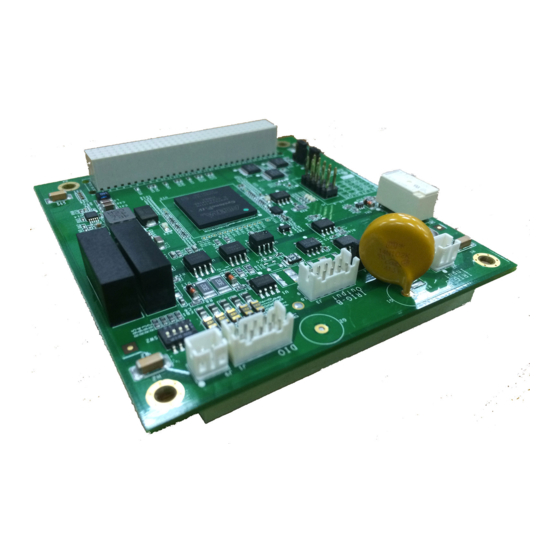
Thank you for purchasing Moxa’s DA-IRIGB-4DIO-PCI104-EMC4 module for embedded computers that support the PCI/104 interface. The DA-IRIGB-4DIO-PCI104-EMC4 module features 3 digital inputs and 4 digital outputs and provides precision timing information using IRIG-B input signals. The following topics are covered in this chapter: ... -
Page 6: Overview
IRIG-B input signals and DIOs in embedded computers. The DA-IRIGB-4DIO-PCI104-EMC4 module includes jumpers that enable you to configure the I/O base address and the INT vector for each port. In addition, the built-in EMC level 4 protection safeguards the module connected to the IRIG-B input signals and digital input and digital output devices. - Page 7 DA-IRIGB-4DIO-PCI104-EMC4 Module Introduction Surge Protection: 2 kV line-to-line and 4 kV line-to-ground surge protection, 8/20 µs waveform Input Signals IRIG-B: TTL or differential Time Code Input IRIG-B: Based on the IRIG STANDARD 200-04 and IEEE 1344 Precision and Accuracy Accuracy (Time Synchronization): ±1 µs Accuracy (Free Running): ±500 ms @ 24 hr...
-
Page 8: Hardware Installation
Hardware Installation This chapter explains how to install the DA-IRIGB-4DIO-PCI104-EMC4 module. The following topics are covered in this chapter: Block Diagram Pin Assignments IRIB-B Signal Input Digital Input and Digital Output Installing the DA-IRIGB-4DIO-PCI104-EMC4... -
Page 9: Block Diagram
DA-IRIGB-4DIO-PCI104-EMC4 Module Hardware Installation Block Diagram Pin Assignments This section includes the pin assignment for the male DB9 connectors to connect to an IRIG-B signal source or a digital input (DI) or digital output (DO) device. IRIB-B Signal Input Differential –... -
Page 10: Installing The Da-Irigb-4Dio-Pci104-Emc4
Installing the DA-IRIGB-4DIO-PCI104-EMC4 ATTENTION To prevent damage to your system or the main board, make sure that you turn off the embedded computer before installing the DA-IRIGB-4DIO-PCI104-EMC4 module. 1. Turn off the embedded computer. 2. Connect the cables. Complete the following actions: a. - Page 11 DA-IRIGB-4DIO-PCI104-EMC4 Module Hardware Installation c. Connect the 10-wire DIO signal cable. 3. Install the four 15 mm spacers on the embedded computer.
- Page 12 DA-IRIGB-4DIO-PCI104-EMC4 Module Hardware Installation 4. Insert the module firmly into an available PCI/104 slot. 5. Install the four screws to secure the module in place.
- Page 13 DA-IRIGB-4DIO-PCI104-EMC4 Module Hardware Installation 6. Secure the DB9 connectors on the rear panel of the embedded computer. 7. Turn on the embedded computer. The BIOS will automatically set the IRQ and I/O address.
-
Page 14: Software Installation And Configuration
Software Installation and Configuration This chapter describes how to install driver and utility for the DA-IRIGB-4DIO-PCI104-EMC4 on an embedded computer running Linux or Windows 7 (64-bit), and how to configure the software settings. The following topic is covered in this chapter: ... -
Page 15: Installing The Irig-B Driver In Linux
3.2.x). Before you install the driver in a different Linux distribution or kernel version, contact your Moxa sales representative for assistance. You can install the Linux driver for the DA-IRIGB-4DIO-PCI104-EMC4 module on the embedded computer using one of the following methods: •... -
Page 16: Off-Line Installation
DA-IRIGB-4DIO-PCI104-EMC4 Module Software Installation and Configuration da-682a-irigb-driver The following NEW packages will be installed: da-682a-irigb-driver da-682a-irigb-timesync-daemon 0 upgraded, 2 newly installed, 0 to remove and 83 not upgraded. Need to get 77.8 kB of archives. After this operation, 0 B of additional disk space will be used. -
Page 17: Using The Timesync Daemon In Linux
DA-IRIGB-4DIO-PCI104-EMC4 Module Software Installation and Configuration DA-682A-irigb_timesync_daemon_1.2_amd64.deb Selecting previously unselected package da-682a-irigb-timesync-daemon. (Reading database ... 31661 files and directories currently installed.) Unpacking da-682a-irigb-timesync-daemon (from DA-682A-irigb_timesync_daemon_1.2_amd64.deb) ... Setting up da-682a-irigb-timesync-daemon (1.2) ... 5. Verify that the driver is loaded and the time sync daemon is running. -
Page 18: Examples
DA-IRIGB-4DIO-PCI104-EMC4 Module Software Installation and Configuration Examples The following command example enables the daemon to synchronize time from Port 1 in DIFF signal type every 10 seconds. The input signal is not inversed. The ServiceSyncTime process runs in the foreground. - Page 19 DA-IRIGB-4DIO-PCI104-EMC4 Module Software Installation and Configuration 2:Set IRIG-B RTC Time -p [2000-2099],[1-12],[1-31],[0-23],[0-59],[0-59] (year[2000-2099],month[1-12],day[1-31],hour[0-23],min[0-59],sec[0-59]); default value is 2014,01,01,00,00,00 3:Get IRIG-B RTC Sync. Source 4:Set IRIG-B RTC Sync. Source -p [0-2] (Source: 0=FreeRun In (Internal RTC), 1=Fiber In, 2=Port 1 In); default value is 2 5:Get IRIG-B Signal Status -p [1-2] (Source: 1=Fiber In, 2=Port 1 In);...
- Page 20 DA-IRIGB-4DIO-PCI104-EMC4 Module Software Installation and Configuration The following table describes the function IDs. Function ID Function description Parameters Display the hardware device ID. For example, Hardware ID = 1 (DA_IRIGB_4DIO_PCI104) Display current internal RTC time. Set internal RTC time yyyy,MM,dd,hh,mm,ss Where yyyy is the year (2000 –...
-
Page 21: Examples
DA-IRIGB-4DIO-PCI104-EMC4 Module Software Installation and Configuration Function ID Function description Parameters Display digital input. port Where 0 is “DI0”, 1 is “DI1”, and 2 is “DI2” NOTE Function IDs 8, 9, 14, and 15 are not available for the DA-IRGB-4DIO-PCI-104-EMC4 module, which does not support the fiber input port. - Page 22 DA-IRIGB-4DIO-PCI104-EMC4 Module Software Installation and Configuration The following command example displays the digital output interface. root@Moxa:~# mxIrigUtil -f 16 -p 0 Get DO 0 = 1 root@Moxa:~# mxIrigUtil -f 16 -p 1 Get DO 1 = 1 root@Moxa:~# mxIrigUtil -f 16 -p 2...
-
Page 23: Installing The Irig-B Driver In Windows 7
DA-IRIGB-4DIO-PCI104-EMC4 Module Software Installation and Configuration # If you need the IRIG-B signal output, you should remove the # in from of the following line. /usr/sbin/mxIrigUtil $MX_IRIGB_UTIL_OPTS > /dev/null 2>&1 Installing the IRIG-B Driver in Windows 7 1. Log into the embedded computer as an administrator. - Page 24 DA-IRIGB-4DIO-PCI104-EMC4 Module Software Installation and Configuration 6. Select install for anyone using this computer and click Next. NOTE Before you select Install just for me, make sure that you understand how this option might affect the operation for other users on the embedded computer.
-
Page 25: Installing The Irig-B Utility In Windows 7
DA-IRIGB-4DIO-PCI104-EMC4 Module Software Installation and Configuration 8. When the installation process is complete, click Finish. Installing the IRIG-B Utility in Windows 7 You can use the IRIG-B utility to view the status information and configure the signal type for the DA-IRIGB-4DIO-PCI104 module. - Page 26 DA-IRIGB-4DIO-PCI104-EMC4 Module Software Installation and Configuration 4. When the welcome screen appears, click Next. 5. Select install for anyone using this computer and click Next. NOTE Before you select Install just for me, make sure that you understand how this option might affect the operation for other users on the embedded computer.
- Page 27 DA-IRIGB-4DIO-PCI104-EMC4 Module Software Installation and Configuration 6. Accept the default destination folder or click Browse to select one; then, click Install. 7. When the installation process is complete, click Finish. 4-14...
-
Page 28: Using The Irig-B Utility In Windows 7
DA-IRIGB-4DIO-PCI104-EMC4 Module Software Installation and Configuration Using the IRIG-B Utility in Windows 7 After you install the IRIG-B utility on your embedded computer running Windows 7, you start the IRIG-B utility from the start menu (click Moxa DA-IRIG-B Utility mxIrigbCardConf) to configure the DA-IRIGB-4DIO-PCI104-EMC4. -
Page 29: Configuring Irig-B Parameters
DA-IRIGB-4DIO-PCI104-EMC4 Module Software Installation and Configuration Configuring IRIG-B Parameters You can use the IRIG-B utility to configure the IRIG-B parameters that the DA-IRIGB-4DIO-PCI104-EMC4 module supports. Input Signal Type In the Moxa IRIG-B Card Configure Utility screen, select Differential or TTL from the Signal Type drop-down list. -
Page 30: Irig-B Parity Mode
DA-IRIGB-4DIO-PCI104-EMC4 Module Software Installation and Configuration IRIG-B Parity Mode Depending on your country, you may need to configure the parity mode. From the IRIG-B Parity Mode drop-down list box, select an option. For example, in China, select Odd charity mode. -
Page 31: Configuring Time Synchronization Settings In Windows 7
DA-IRIGB-4DIO-PCI104-EMC4 Module Software Installation and Configuration Configuring Time Synchronization Settings in Windows 7 In the IRIG-B utility, you can set the DA-IRIGB-4DIO-PCI104-EMC4 module to synchronize the RTC using one of the following time input sources: • External IRIG-B signal •... -
Page 32: Configuring Digital Output And Input Status
Software Installation and Configuration Configuring Digital Output and Input Status The DA-IRIGB-4DIO-PCI104-EMC4 module features four digital outputs and three digital inputs. You can use IRIG-B utility configure the digital output and digital input status. To control a digital output, select or clear the associated check box. The following table shows the signal and logic state for the check box. -
Page 33: Using The Mxirigutil Command
DA-IRIGB-4DIO-PCI104-EMC4 Module Software Installation and Configuration Using the mxIrigUtil Command The mxIrigUtil command is available in the destination folder that you selection during the installation process. The list of available parameters and options for the mxIrigUtil command is the same in Linux and Windows 7. - Page 34 DA-IRIGB-4DIO-PCI104-EMC4 Module Software Installation and Configuration Function ID Function description Parameters Display input signal type. port [0|1] Where 1 is port 1 input. Set input signal type. port, signal type, mode, inverse Where port – 1 is “Port 1” signal type – 0 is TTL; 1 is “DIFF”...
-
Page 35: Api Reference
API Reference This chapter describes the available APIs that you can use to develop your own time synchronization and digital input/digital output control applications. The following topics are covered in this chapter: Get IRIG-B Board Hardware ID Open IRIG-B Device ... -
Page 36: Get Irig-B Board Hardware Id
DA-IRIGB-4DIO-PCI104-EMC4 Module API Reference Get IRIG-B Board Hardware ID MXIRIG_API BOOL mxIrigbGetHardwareID (HANDLE hDev, PDWORD pdwHwId) Parameters hDev The handle for value returned from the mxIrigbOpen function. pdwHwId The pointer for the hardware ID Returns If the operation completes successfully, the return value is nonzero. If the operation fails or is pending, the return value is zero. -
Page 37: Get Digital Output Signal
DA-IRIGB-4DIO-PCI104-EMC4 Module API Reference Returns If the operation completes successfully, the return value is nonzero. If the operation fails or is pending, the return value is zero. To display detailed error information, use GetLastError. Get Digital Output Signal MXIRIG_API BOOL mxIrigbGetDigitalOutputSignal (HANDLE hDev, DWORD dwPort, PDWORD pValue) -
Page 38: Get Irig-B Output Parity Check Mode
DA-IRIGB-4DIO-PCI104-EMC4 Module API Reference inversed. Returns If the operation completes successfully, the return value is nonzero. If the operation fails or is pending, the return value is zero. To display detailed error information, use GetLastError. Get IRIG-B Output Parity Check Mode... -
Page 39: Get Irig-B Signal Status
DA-IRIGB-4DIO-PCI104-EMC4 Module API Reference Returns If the operation completes successfully, the return value is nonzero. If the operation fails or is pending, the return value is zero. To display detailed error information, use GetLastError. Get IRIG-B Signal Status MXIRIG_API BOOL mxIrigbGetSignalStatus (HANDLE hDev, DWORD dwSource, PDWORD pdwStatus) -
Page 40: Set Digital Output Signal
DA-IRIGB-4DIO-PCI104-EMC4 Module API Reference Set Digital Output Signal MXIRIG_API BOOL mxIrigbSetDigitalOutputSignal (HANDLE hDev, DWORD dwPort, DWORD value) Parameters hDev A valid handle value returned from the mxIrigbOpen function. dwPort The port number (starting from 0). value The port data (1:HIGH, 0:LOW). -
Page 41: Set Irig-B Output Parity Check Mode
DA-IRIGB-4DIO-PCI104-EMC4 Module API Reference Set IRIG-B Output Parity Check Mode MXIRIG_API BOOL mxIrigbSetOutputParityCheckMode (HANDLE hDev, DWORD dwMode) Parameters hDev A valid handle value returned from the mxIrigbOpen function. dwMode PARITY_CHECK_MODE to set the parity check mode. Returns If the operation completes successfully, the return value is nonzero. If the operation fails or is pending, the return value is zero. -
Page 42: Set Rtc To Irig-B Device
DA-IRIGB-4DIO-PCI104-EMC4 Module API Reference Parameters hDev A valid handle value returned from the mxIrigbOpen function. dwSource RTC_SYNC_SOURCE to select the RTC synchronization source. Returns If the operation completes successfully, the return value is nonzero. If the operation fails or is pending, the return value is zero. - Page 43 DA-IRIGB-4DIO-PCI104-EMC4 Module API Reference HANDLE irigbCardHandle; irigbCardHandle = mxIrigbOpen(0); if( irigbCardHandle < 0 ) { fprintf(stderr,"mxIrigbOpen() fail!\n"); return 0; /* 3.1. Reference the IRIG-B API to control the IRIG-B module. EX: set the sync time source */ if (!mxIrigbSetSyncTimeSrc(irigbCardHandle, time_source) ) { printf("Set sync source fail\n");...
- Page 44 DA-IRIGB-4DIO-PCI104-EMC4 Module API Reference 4-10...
Need help?
Do you have a question about the DA-IRIGB-4DIO-PCI104-EMC4 and is the answer not in the manual?
Questions and answers