
Related Manuals for Moxa Technologies CA Series


Summary of Contents for Moxa Technologies CA Series
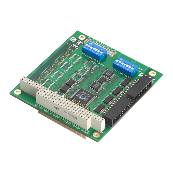
- Page 1 CA and CB Series Multiport Serial Module User’s Manual Edition 8.1, November 2017 www.moxa.com/product © 2017 Moxa Inc. All rights reserved.
- Page 2 CA and CB Series PC/104 Multiport Serial Module User’s Manual The software described in this manual is furnished under a license agreement and may be used only in accordance with the terms of that agreement. Copyright Notice © 2017 Moxa Inc. All rights reserved. Trademarks The MOXA logo is a registered trademark of Moxa Inc.
-
Page 3: Table Of Contents
Product Specifications ......................... 1-3 Hardware Installation ........................2-1 Hardware Installation .......................... 2-2 Block Diagrams ..........................2-2 I/O Base Address (For CA Series) ....................2-4 Rotary Switch(For CB Series) ......................2-5 Termination Resistor ........................2-5 Interrupt Vector for CA Series ....................... 2-5 Serial Interface........................... -
Page 4: Introduction
It is designed for the PC/104 CPU and PC/104-Plus boards that respectively accept the PC/104 and PC/104-Plus expansion interface. Optional DB9 and DB25 cables are available to connect different devices. The CA Series includes the following models: CA-108: 8 ports, RS-232... -
Page 5: Overview
You may also use this package to return the module if it requires repair. The CA/CB Series module is shipped with the following items: • Multiport serial module (PC/104 is for CA Series; PC/104-Plus is for CB Series) • Documentation and software CD •... -
Page 6: Product Specifications
CA Series PC/104 Introduction Product Specifications CA Series PC/104 Multiport Serial Module Hardware I/O controller 16C550C or compatible Connector Type 40-pin box header (CA-108, CA-114, CA-134I, CA-104 ) 20-pin box header (CA-132 , CA-132I ) Interface PC/104 bus (Ver. 2.4) No. - Page 7 CA Series PC/104 Introduction CB Series PC/104-Plus Multiport Serial Module Hardware I/O controller MU860 (16C550C compatible) Connector Type 40-pin box header Interface PC/104-Plus (PCI) bus No. of Ports 4 ports (CB-114, CB-134I) 8 ports (CB-108) Max. No. of Modules Signals...
-
Page 8: Hardware Installation
This chapter explains how to install the CA/CB Series multiport serial module. The following topics are covered in this chapter: Hardware Installation Block Diagrams I/O Base Address (For CA Series) Rotary Switch(For CB Series) Termination Resistor Interrupt Vector for CA Series... -
Page 9: Hardware Installation
Hardware Installation Hardware Installation Installing the CA/CB Series module is easy. For the CA Series, before inserting the module into the PC/104 slot, you must first configure the I/O base address, interrupt vector, IRQ, and serial interface (for select models). - Page 10 CA Series PC/104 Hardware Installation CA-114 CA-134I, CA-132 , CA-132I CA-104...
-
Page 11: I/O Base Address (For Ca Series)
CB-114 CB-134I I/O Base Address (For CA Series) Use DIP switch SW1 to set port 1’s I/O base address. The other ports will be configured automatically. The default I/O base address is 0×180 and allows settings from 0×000 to 0×3FF. Some popular settings are provided below: 0×000... -
Page 12: Rotary Switch(For Cb Series)
Onboard termination resistors can be activated individually for each serial port using jumpers. With regard to the CA Series: for CA-114 and CA-134I, use JP1 through JP4; for CA-132 and CA-132I, use JP1 and JP2. JP1 corresponds to serial port 1. For the CB Series, use jumpers JP1 through JP4. JP1 corresponds to serial port 1. -
Page 13: Serial Interface
CA Series PC/104 Hardware Installation = on, = off Serial Interface CA Series For the CA-114, use SW3, SW4, and SW5 to select the serial interface as follows: Interface RS-232 RS-422 RS-485 RS-485 – – – For the CA-134I, CA-132 , and CA-132I , use the 2-WIRE/4-WIRE and RS-422/RS-485 DIP switches to select... - Page 14 CA Series PC/104 Hardware Installation IRQ for CA Series Before selecting an IRQ, please enter the PC’s BIOS and reserve a dedicated IRQ for the module. On the module, the IRQ is set by a jumper. Before inserting the module into the PC/104 slot, use the jumper to select an IRQ...
-
Page 15: Software Installation
CA/CB Series driver. The following topics are covered in this chapter: Windows OS Older OS for CA Series Older OS for CB Series Newer OS for Both CA/CB Series Non-Windows OS... -
Page 16: Windows Os
Software Installation Windows OS Older OS for CA Series Moxa DOS API-232 is a software package that can help you develop or debug serial communications programs. This section will explain how to install the package, set up the driver, and load or unload the driver. For additional information about the API-232 library and utilities, please refer to Chapter 4. - Page 17 F1 in the setup program. 1. Run the setup program BIN\SETUP.EXE. 2. Select your CA Series model and press Enter. 3. You must set the Port No., I/O Address, IRQ, and INT Vector properly. These settings must match your module’s hardware configuration.
- Page 18 CA Series PC/104 Software Installation 5. Verify the settings and make any necessary changes. Port number: This is the port ID of each port. Application software will refer to a port by its port number (ID). Port numbers must be unique; duplicated port numbers are not allowed.
- Page 19 After setting up the driver, you must load the driver in order to gain access to the serial ports on the module. Run BIN\DPC-DRV.EXE at the DOS prompt. The driver will detect your CA Series module automatically. You should see messages indicating successful detection of your module, such as the following: PC/104 Communication Module DOS driver Version 1.0...
- Page 20 CA Series PC/104 Software Installation 3. When prompted to select a network adapter, click Have Disk. 4. At the prompt, insert the installation disk provided with your module. For the location, enter A:\windows.nt. Click OK to continue. 5. Windows will install the drivers.
- Page 21 6. After the files have been installed, a configuration panel will open. Click Add to continue. 7. Under Board Type, select your CA Series model. The window will show the COM port numbers that will be assigned to the CA Series serial ports, as well as other settings. Click OK to continue.
- Page 22 CA Series PC/104 Software Installation 8. The CA Series module will appear as a network adapter. Click OK to complete installation of the module. Uninstalling the Module 1. Right-click Network Neighborhood and select Properties in the context menu.
- Page 23 The Windows 95/98/ME drivers conform to the Win32 COMM API standard and support the CA-104, CA-104-T, CA-132, CA-132-T, CA-132I, CA-132I-T, CA-108, CA-114, and CA-134I. In the following instructions, the CA-104 is used as an example. Installing the Driver 1. Insert the CA Series installation disk and run Setup95.exe through Start menu Run.
- Page 24 CA Series PC/104 Software Installation 2. Click Next to proceed through the Welcome screens. 3. Windows will install the drivers. When the installation has been completed, click Finish. 3-10...
- Page 25 4. After the files have been installed, a configuration panel will open. Click Add to continue. 5. Under Board Type, select your CA Series model. The window will show the COM port numbers that will be assigned to the CA Series serial ports, as well as other settings. Click OK to continue.
- Page 26 CA Series PC/104 Software Installation 6. The CA Series module will now appear in the configuration panel. Click OK to complete installation of the module. Open the configuration panel again through Start Programs Moxa Utilities MOXA PC104 Communication Module Configuration Panel.
- Page 27 CA Series PC/104 Software Installation 3. To remove the driver from the system, open Add/Remove Programs in the Control Panel. 4. Under the Install/Uninstall tab, select MOXA PC104 Communication Module Driver and click Add/Remove. 3-13...
- Page 28 Windows CE 5.0 In this section, we explain how to install Moxa CA series boards under WinCE 5.0. These instructions are intended for users who are familiar with the Windows CE Platform Builder 5.0 ToolKit, and who would like to install one or more Moxa Tech products.
- Page 29 CA Series PC/104 Software Installation 3. Enter a workspace name and then press Next. 4. When you see Board Support Packages, Design Template, Applications & Media, Networking & Communications, OBEX Server, select what you need to build your own environment. The Completing the New Platform Wizard window will open to indicate that it has created a new platform.
- Page 30 CA Series PC/104 Software Installation 3-16...
- Page 31 CA Series PC/104 Software Installation 5. Select File Manage Catalog Items In View Catalog, and browse \Third Party\Device Drivers\ MOXA Smartio/Industio-PC/104. Right-click on the driver Prefix COM or Prefix MXU you would like to include and choose Add to OS Design.
- Page 32 CA Series PC/104 Software Installation be allowed to use one multiport serial board on the target host. 6. After adding Moxa Tech drivers into your OS Design, a new project is automatically added to your workspace. The project name is mxpcdrvce5.reg. The project can be accessed from View File View. The mxpcdrvce5.reg project contains a number of files used to configure the drivers included in your OS Design.
- Page 33 CA Series PC/104 Software Installation 7. Finally, open Build OS, select Build and Sysgen, and be sure to click Copy Files to Release Directory After Build and Make Run-Time Image After Build. 8. Finally, copy your image file to the target host.
-
Page 34: Older Os For Cb Series
CA Series PC/104 Software Installation Older OS for CB Series Moxa DOS API-232 is a software package that can help you develop or debug serial communications programs. This section will explain how to install the package, set up the driver, and load or unload the driver. For additional information about the API-232 library and utilities, please refer to Chapter 4. - Page 35 CA Series PC/104 Software Installation Driver Setup The following instructions are not intended to illustrate every function of the setup program. For more detailed information, please refer to the help files by pressing F1 in the setup program. 1. Run the setup program BIN\SETUP.EXE.
- Page 36 CA Series PC/104 Software Installation 5. Press F10 to save the latest configuration and exit the setup program. Loading the Driver After setting up the driver, you must load the driver in order to gain access to the serial ports on the module.
- Page 37 CA Series PC/104 Software Installation Windows NT Installing the Driver You will need to plug the board in an available PCI or PCI-X slot first, before installing the driver. Note that these instructions use the CB-114 as an example. The procedure for installing all models is the same.
- Page 38 CA Series PC/104 Software Installation 5. After the files have been installed, a configuration panel will open. This is where boards are installed, configured, and removed. If another board has already been installed on the system, it will already be listed.
- Page 39 CA Series PC/104 Software Installation 7. The board will now appear in the configuration panel (CB-114 Series in this example). Click OK to return to the Network applet. After that, click OK again to exit the Network applet 8. Restart the PC. After you have logged back into Windows NT, you may check the event log issued by the Moxa driver to see if the board’s ports have been initialized successfully.
- Page 40 CA Series PC/104 Software Installation 2. The configuration panel will open with a list of installed boards. Select your board and click Property. Up to four Moxa UPCI boards can be installed at a time. 3. Select a port to configure and click Port Setting.
- Page 41 CA Series PC/104 Software Installation Under Port Number, select a COM number to assign to the serial port. Select Auto Enumerating COM Number to map subsequent ports in numerical order. For example, if COM 3 is assigned to Port 1, then COM 4 will be automatically assigned to Port 2.
- Page 42 CA Series PC/104 Software Installation Updating the Driver 1. In Windows Control Panel, open the Network applet. Under the Adapters tab, UPCI boards will appear as a type of Moxa adapter (MOXA Smartio/Industio Family Adapter in this example). Select the Moxa adapter and click Remove.
- Page 43 CA Series PC/104 Software Installation Windows 95/98/ME Installing the Driver Windows 95 1. After the board is physically installed and the PC boots up, Windows will automatically detect the new board and the Found New Hardware Wizard window will open. Click Next to continue.
- Page 44 CA Series PC/104 Software Installation 4. After Windows finds the drivers, click Finish. You can configure and use the new COM ports right away without restarting Windows. Windows 98 and ME 1. After the board is physically installed and the PC boots up, Windows will automatically detect the new board and the Found New Hardware Wizard window will open.
- Page 45 CA Series PC/104 Software Installation 2. Select Display a list... and click Next. 3. Select Other Devices and click Next. 4. Select Have Disk… 5. Click Browse and select the appropriate directory on the Document & Software CD for the driver. Drivers for all operating systems are located under the product folder in the \Software directory.
- Page 46 CA Series PC/104 Software Installation 6. After Windows has installed the drivers, click Finish. Configuring the Ports Configure the COM ports after the board and drivers have been installed. 1. In the Windows Control Panel, open the System applet. 3-32...
- Page 47 CA Series PC/104 Software Installation 2. In the Device Manager tab, expand the Moxa Smartio/Industio multiport board category by clicking the “+” sign next to it. Select the desired board and click Properties. 3. Under the Ports Configuration tab, select a port to configure and click Port Setting.
- Page 48 CA Series PC/104 Software Installation Under Port Number, select a COM number to assign to the serial port. Select Auto Enumerating COM Number to map subsequent ports in numerical order. For example, if COM 3 is assigned to Port 1, then COM 4 will be automatically assigned to Port 2.
- Page 49 CA Series PC/104 Software Installation 2. Under the Device Manager tab, expand the Moxa Smartio/Industio multiport board category by clicking the “+” sign next to it. Select the desired board and click Properties. 3. In the Driver tab, click Update Driver..
- Page 50 CA Series PC/104 Software Installation 4. Select the appropriate model (CP-168U in this example) and click Have Disk... 5. When prompted, select the appropriate directory on the Document & Software CD for the driver. Drivers for all operating systems are located under the product folder in the \Software directory. Select the \Win9x folder and click OK to continue.
- Page 51 CA Series PC/104 Software Installation 3. After the driver has been removed, click OK to return to the Add/Remove Programs applet. Windows CE 5.0 In this section, we explain how to install Moxa CB series boards under WinCE 5.0. These instructions are intended for users who are familiar with the Windows CE Platform Builder 5.0 Toolkit, and would like to install...
- Page 52 CA Series PC/104 Software Installation 3. Enter a name for Workspace and press Next. 4. When you see Board Support Packages, Design Template, Applications & Media, Networking & Communications, OBEX Server, select what you need to build your own environment. The Completing the New Platform Wizard window will open to indicate that it has finished creating a new platform.
- Page 53 CA Series PC/104 Software Installation 3-39...
- Page 54 CA Series PC/104 Software Installation 3-40...
- Page 55 CA Series PC/104 Software Installation 5. Open Manage Catalog Items (File Manage Catalog Items). Under Catalog (View Catalog), browse t\Third Party\Device Drivers\ MOXA Smartio/Industio-PCI, PC/104-Plus. Right-click on the driver Prefix COM or Prefix MXU you would like to include and choose Add to OS Design.
- Page 56 CA Series PC/104 Software Installation 6. After adding Moxa Tech drivers into your OS Design, a new project is automatically added to your workspace. The project name is mxserce5. The project can be accessed from File View (View File View).
-
Page 57: Newer Os For Both Ca/Cb Series
CA or CB boards. NOTE In the installation section, the CA Series has more installation procedures as it follows the ISA standard. The content will be added, followed by the installation part of CB Series. - Page 58 CA Series PC/104 Software Installation Installing the Driver In this section, we will describe how to install the CA or CB boards for the first time with Windows 7. First, make sure that you have already plugged the board or boards into the system’s PC/104 or PC/104-Plus slot(s).
- Page 59 CA Series PC/104 Software Installation 3. Click Next to install the driver in the indicated folder, or use the drop-down folder list to locate a different folder. 4. Click Install to proceed with the installation. 3-45...
- Page 60 If your model is from the CB Series, then the installation is done. Otherwise, you need to do the following steps to complete the installation for the CA Series (CA-114 Series is taken as example). 1. Select Add Hardware Wizard from the Control Panel. When the wizard opens, click Next to continue.
- Page 61 CA Series PC/104 Software Installation 2. Select Yes, I have already connected the hardware and click Next to continue. 3. Select Add a new hardware device and click Next to continue. 3-47...
- Page 62 CA Series PC/104 Software Installation 4. Select Install the hardware that I manually select from a list (Advanced) and click Next to continue. 5. Select Multi-port serial adapters and click Next to continue. 3-48...
- Page 63 CA Series PC/104 Software Installation 6. Select your CA Series model and click Next to continue. 7. To begin installing the module, click Next. 3-49...
- Page 64 CA Series PC/104 Software Installation 8. If you see a warning that the software has not passed Windows Logo testing, click Continue Anyway. 9. Windows will install the drivers. When the installation has been completed, click Finish. 3-50...
- Page 65 CA Series PC/104 Software Installation 10. After the module has been installed, you will be prompted to install the new serial ports. A Found New Hardware Wizard window will open for the first serial port, port 0. Select No, not this time and click Next.
- Page 66 CA Series PC/104 Software Installation 12. Select Search for the best driver in these locations and Include this location in the search. Select the \Program Files\MOXA\SmartioIndustioDriver folder on the C drive disk, and click Next. 13. If you see a warning that the software has not passed Windows Logo testing, click Continue Anyway.
- Page 67 CA Series PC/104 Software Installation 15. After the installation is complete, click Finish. 16. Repeat the installation process for the remaining serial ports. Configuring the Ports After the driver has been installed, use Device Manager to configure the serial port of your CA or CB boards (CB-134I Series will be used as example).
- Page 68 CA Series PC/104 Software Installation Accessing MOXA Smartio/Industio Window Driver Expand the Multi-port serial adapters tab, right-click CB-134I Series (PC/104-Plus), and then click Properties to open the board’s configuration panel. Configuring the Serial Ports Port Number 1. Click the port you would like to configure to highlight it and then click Port Setting.
- Page 69 CA Series PC/104 Software Installation 2. Select a COM number for the port from the Port Number pull-down list. Select the Auto Enumerating COM Number option to map subsequent ports automatically. The port numbers will be assigned in sequence. For example, if COM 1 is assigned to Port 1, then COM 2 (if not already occupied) will be assigned to Port 2, etc.
- Page 70 CA Series PC/104 Software Installation To start the program, click Start Programs MOXA PComm Ver 1.X PComm Diagnostic NOTE You can download the PComm Lite software for free from Moxa’s website at www.moxa.com/support/free_downloads.htm. 3-56...
- Page 71 CA Series PC/104 Software Installation Removing the Driver 1. Open the Device Manager and use the mouse to place the cursor over the MOXA CB-134I Series (PC/104-Plus boards) under Multi-port serial adapters, right-click, and then select the Uninstall option. 2. Select Delete the driver software for this device and click OK to proceed with uninstalling the board.
- Page 72 CA Series PC/104 Software Installation Uninstallating the Driver The MSB driver may be removed through Add/Remove Programs in the Windows Control Panel. Click Uninstall next to MOXA Smartio/Industio Windows Driver Verx.xx 3-58...
-
Page 73: Non-Windows Os
0x180, an INT vector of 0x1C0, and an IRQ of 10, execute the following command: #modprobe mxpcdrv ioaddr=0x180 iovect=0x1C0 irq=10 (This step is only for CA Series) 5. You can use the Moxa diagnostic utility to verify the driver’s status: #cd /moxa/mxpcdrv/utility/diag #./msdiag... -
Page 74: Serial Programming Tools
Serial Programming Tools Moxa provides Windows serial programming libraries and troubleshooting utilities that are easy to use and powerful. You can use these tools to reduce software development time. The serial communication library is useful for developing applications for data communications, remote access, data acquisition, and industrial control. -
Page 75: Serial Programming Library
CA Series PC/104 Serial Programming Tools Serial Programming Library The serial programming library assists you in developing serial communications programs for any COM port that complies with the Microsoft Win32 API. It facilitates the implementation of multi-process and multi-thread serial communication programs and can remarkably reduce development time. -
Page 76: Pcomm Monitor
CA Series PC/104 Serial Programming Tools PComm Monitor PComm Monitor is designed for Moxa board in Windows NT only. It allows you to monitor data transmission of selected Moxa COM ports. It monitors data transmission, throughput, and line status at regular intervals. Click on a specific port to view that port’s communication parameters and status. -
Page 77: Smartio/Industio Programming Guide
Smartio/Industio Programming Guide If you want to develop your own driver, no matter whether it is on a Windows or Linux platform, Moxa Smartio/Industio Programming Guide is very useful. The following topics are covered in this chapter: Relative Product List ... -
Page 78: Relative Product List
CA Series PC/104 Smartio/Industio Programming Guide Relative Product List Please see the “Moxa Board PCI Device ID List” at the end of this document. Resource Requirement for Moxa Board IRQ * 1 I/O : UART register: 64 bytes (8 bytes/port * 8port) for MU860... -
Page 79: Uart Register Structure For Mu860 Chip
CA Series PC/104 Smartio/Industio Programming Guide UART Register Structure for MU860 chip NOTE For a detailed UART register description, please see the “UART Datasheet” section.. UART register address = I/O base address + (port-1) *8 For example, if the base address is 0x180: The first port’s UART registered I/O address is 0x180+(1-1)*8 = 0x180... -
Page 80: Uart Register Structure For Mue250, Mue450, And Mue850 Chips
CA Series PC/104 Smartio/Industio Programming Guide UART Register Structure for MUE250, MUE450, and MUE850 chips There are 512 bytes for each UART register and 0x200 offset between each port. However, there is one exception, for the models which are 4-port boards, such as CP-104EL-A, CP-114EL, CP-114EL-I, and CP-134EL-A, the offset of the fourth UART register is 0xE00. -
Page 81: For Baud Rate Setting
CA Series PC/104 Smartio/Industio Programming Guide Control Serial Interface and Termination Resistor for MUE chips For Moxa boards that use MUE250, MUE450, and MUE850 chips, BAR2, which is allocated 16 bytes. is the vector base address that can be used to control the serial interface and termination resistor according to the following table. -
Page 82: Moxa Board Pci Device Id List
CA Series PC/104 Smartio/Industio Programming Guide Moxa Board PCI Device ID List Model Ports Chip Max Baud Vendor ID Device ID CP-102U UPCI MU860 921.6k 0x1393 0x1022 CP-102UL UPCI MU860 921.6k 0x1393 0x1021 CP-132UL UPCI MU860 921.6k 0x1393 0x1321 CP-132UL-I... -
Page 83: Pin Assignments
GND1 GND2 GND3 RS-422, 4-wire RS-485 These pin assignments apply to the CA-132, CA-132I , CA-114/CB-114, and CA-134I/CB1341. With regard to the CA Series, pins 21 to 40 apply to the CA-114 and CA-134I only. Signal Signal Pin* Signal* Pin*... -
Page 84: 2-Wire Rs-485
CA Series PC/104 Pin Assignments 2-wire RS-485 These pin assignments apply to the CA-132 , CA-132I , CA-114/CB-114, and CA-134I/CB-1341. With regard to the CA series, pins 21 to 40 apply to the CA-114 and CA-134I only. Signal Signal Pin*...
Need help?
Do you have a question about the CA Series and is the answer not in the manual?
Questions and answers