
Related Manuals for Moxa Technologies MiiNePort E1 Series


Summary of Contents for Moxa Technologies MiiNePort E1 Series
- Page 1 MiiNePort E1 Series User Manual Version 8.1, January 2022 www.moxa.com/product © 2022 Moxa Inc. All rights reserved.
- Page 2 Product Name User Manual The software described in this manual is furnished under a license agreement and may be used only in accordance with the terms of that agreement. Copyright Notice © 2022 Moxa Inc. All rights reserved. Trademarks The MOXA logo is a registered trademark of Moxa Inc. All other trademarks or registered marks in this manual belong to their respective manufacturers.
-
Page 3: Table Of Contents
Table of Contents Introduction ............................6 Overview .............................. 6 Package Checklist ..........................6 Product Features ........................... 6 NetEZ..............................7 MiiNePort E1 Module Dimensions ...................... 9 Recommended Device PCB Layout ....................9 Panel Layout and Pin Assignments ......................10 MiiNePort E1-ST Evaluation Board Panel Layout ................10 Pin Assignments ........................... - Page 4 Mapping TTY Ports ........................43 Mapping TTY Ports Automatically ....................43 Mapping TTY Ports Manually ......................44 Editing Mapped TTY Ports ......................45 Removing Mapped TTY Ports ......................45 Uninstalling NPortConnect ......................45 Web Console Configuration ......................... 46 Opening Your Brower ........................... 46 Web Console Fundamentals ........................
- Page 5 Response ..........................132 C Code Example ......................... 132 Read Multiple DIOs ..........................133 Command ..........................133 Response ..........................133 C Code Example ......................... 134 Write Multiple DIOs ..........................134 Command ..........................134 Response ..........................135 C Code Example ......................... 136 SNMP Agent with MIB II and RS-232 Like Groups ................
-
Page 6: Introduction
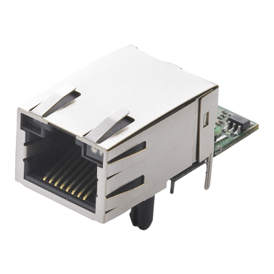
1. Introduction The MiiNePort E1 Series embedded device servers are compact drop-in modules that can be integrated with your serial devices to enable connectivity to an Ethernet network. All MiiNePort E1 Series modules come equipped with built-in TCP/IP protocols and other easy-to-use network enabling tools for fast integration, allowing you to provide network access to any electronic device with a serial port. -
Page 7: Netez
NetEZ SCM (Serial Command Mode) can easily configure the MiiNePort E1 through serial communication inside the device. MiiNePort E1 Series User Manual... - Page 8 When you are in RS-485 mode, 485EN must be configured by either JP15 or JP16, and the 6-pin jumper must be moved from JP19 to JP20. ATTENTION Before you manipulate the jumpers, be sure to disconnect the power first. MiiNePort E1 Series User Manual...
-
Page 9: Miineport E1 Module Dimensions
MiiNePort E1 Module Dimensions MiiNePort E1 Series User Manual... -
Page 10: Panel Layout And Pin Assignments
Pin 7 can be configured as Reset to Default, DIO, DTR, or RS-485 Tx • Enabled (the default is Reset to Default). Pin 8 can be configured as CTS (Clear to Send), DI, or DSR • (the default is CTS). MiiNePort E1 Series User Manual... -
Page 11: Block Diagram
Ethernet Port Pins for MiiNePort E1 Modules RJ45 Signal Serial Pin Signals for the MiiNePort E1-ST Evaluation Board DB9 Male RS-232 2-wire RS-485 – – Data+ Data- – – – Block Diagram MiiNePort E1 Series User Manual... -
Page 12: Led Indicators
LED D13 shows the RTS status LED D14 shows the CTS status • Digital Output LED LED D17 shows the DO0 (Pin No. 6) status • • LED D18 show the DO1 (Pin No. 7) status. MiiNePort E1 Series User Manual... -
Page 13: Getting Started
2. Getting Started This chapter includes information about how to install MiiNePort E1 Series modules for development and testing. Wiring Precautions This section describes some important safety precautions that you should pay attention to before proceeding with any installation. ATTENTION Be sure to disconnect the power cord before installing or wiring the evaluation board. -
Page 14: Selecting The Serial Interface
RS-485 To use an RS-485 serial interface, place the 2-pin jumper on the middle two pins of JP15 or the right-most two pins of JP16 (labeled as 485EN), and place the 6-pin jumper on JP20. MiiNePort E1 Series User Manual... -
Page 15: Circuit Pad For External Connection
Fault (blinks when IP fault) When using a private IP address for the module, which is the factory default, make sure the netmask and IP settings are configured properly to access the module from a host on the network. MiiNePort E1 Series User Manual... -
Page 16: Connecting To A Serial Device
Digital Output LED as your output device, Low status is indicated by the LED lighting up, and High status is indicated by the LED turning off. Schematic Design Guide For guidance and suggestions on integrating your device’s hardware with the MiiNePort E1, refer to the MiiNePort E1 Schematic Design Guide at http://www.moxa.com. MiiNePort E1 Series User Manual... -
Page 17: Choosing The Proper Operation Mode
The driver thus establishes a transparent connection between the host and serial device, allowing the host to treat the networked device as if it was directly attached. MiiNePort E1 Series User Manual... -
Page 18: Tcp Modes
The host connects to the module configured for TCP Server mode. Once the connection is established, data can be transmitted in both directions—from the host to the module, and from the module to the host. MiiNePort E1 Series User Manual... -
Page 19: Tcp Client Mode
Once the connection is established, data can be transmitted in both directions—from the host to the module, and from the module to the host. MiiNePort E1 Series User Manual... -
Page 20: Tcp Mixed Mode
Ethernet card. NOTE To select RFC 2217 mode, first select TCP Server mode and then set Communication protocol to RFC 2217. For more details, refer to Chapter 7: Web Console Configuration. MiiNePort E1 Series User Manual... -
Page 21: Udp Mode
For example, if you need your device to act as a TCP Server and TCP Client at the same time (as illustrated below), you can use MCSC. For details on MCSC’s functionality and configuration, refer to “Chapter 8: NetEZ Technologies.” MiiNePort E1 Series User Manual... -
Page 22: Choosing The Configuration Tool
COM ports on your PC to serial ports on the MiiNePort Refer to Chapter 6: Utility Console and Driver Installation for details on how to use the Device Search Utility and the NPort Windows Driver Manager. MiiNePort E1 Series User Manual... -
Page 23: Web Console
Your MiiNePort E1 can be configured over the network with Telnet, which requires that the module has a network connection and an IP address. We briefly discuss Telnet console configuration in Chapter 5: Initial IP Address Configuration. All Telnet console commands are introduced in Chapter 7: Web Console Configuration. MiiNePort E1 Series User Manual... -
Page 24: Scm (Serial Command Mode)
IP address with the device’s keypad, is required. Refer to Chapter 7: Web Console Configuration for details on how to access and use the MiiNePort E1’s SCM. Refer to Appendix A: Introduction to SCM (Serial Command Mode) Command Set instructions. MiiNePort E1 Series User Manual... -
Page 25: Initial Ip Address Configuration
In order to use ARP, both your computer and the module must be connected to the same LAN. You may also use a cross-over Ethernet cable to connect the module directly to your computer’s Ethernet port. Your module must be configured with the factory default IP address before executing the ARP command. MiiNePort E1 Series User Manual... -
Page 26: Telnet Console
IP address by typing telnet 192.168.127.254 in the Open text box. Click OK to proceed. You will be asked to enter a password to access to the device. The default password for MiiNePort E1 is moxa. MiiNePort E1 Series User Manual... - Page 27 Select Network settings by pressing 0 and then press Enter. Select IP address by pressing 1 and then press Enter. MiiNePort E1 Series User Manual...
- Page 28 Use the backspace key to erase the current IP address. Type in the new IP address and then press Enter. Press any key to continue. MiiNePort E1 Series User Manual...
- Page 29 Press M and then Enter to return to the main menu. Press S and then Enter to Save/Restart the system. MiiNePort E1 Series User Manual...
- Page 30 Press Y and then Enter to save the new IP address and restart the module. MiiNePort E1 Series User Manual...
-
Page 31: Utility Console And Driver Installation
Click the INSTALL UTILITY button in the MiiNePort E1 Installation CD auto-run window to install the Device Search Utility. Once the program runs, click Yes to proceed. Click Next when the Welcome screen opens to proceed with the installation. MiiNePort E1 Series User Manual... - Page 32 Click Browse to select an alternate location and then click Next to install program files to the directory displayed in the input box. Select the additional tasks you would like to set up to be performed while installing the DSU; then, click Next. MiiNePort E1 Series User Manual...
- Page 33 The installer will display a summary of the installation options. Click Install to begin the installation. The setup window will report the progress of the installation. To change the installation settings, click Back and navigate to the previous screen. Click Finish to complete the installation of the Device Search Utility. MiiNePort E1 Series User Manual...
-
Page 34: Device Search Utility Configuration
If you are looking for information related to TCP, RFC2217, or UDP modes, you can ignore the following Driver sections, including NPort Windows Driver Manager and Linux Real TTY Driver, and instead jump directly to Chapter 7: Web Console Configuration for additional settings. MiiNePort E1 Series User Manual... -
Page 35: Nport Windows Driver Manager
Click Next when the Welcome screen opens to proceed with the installation. Click Browse to select the destination directory and then click Next to install program files to the directory displayed in the input box. MiiNePort E1 Series User Manual... - Page 36 The setup window will report the progress of the installation. To change the installation settings, click Back and navigate to the previous screen. Click Finish to complete the installation of the NPort Windows Driver Manager. MiiNePort E1 Series User Manual...
-
Page 37: Using The Nport Windows Driver Manager
COM mapping utility. Click the Add icon. Click Search to search for the MiiNePort E1 modules. From the list that is generated, select the server to which you will map COM ports, and then click OK. MiiNePort E1 Series User Manual... - Page 38 COM port until the COM ports are activated. Click Yes to activate the COM ports at this time, or click No to activate the COM ports later. Ports that have been activated will appear in black. MiiNePort E1 Series User Manual...
-
Page 39: Command Line Installation/Removal
Once the NPort Windows Driver Manager v1.19 (or above) is installed, call up the cmd screen on your computer. Change the directory to the drive where you placed the above two files. Type npcli /? to get detailed information of what command lines are supported and the function descriptions. MiiNePort E1 Series User Manual... - Page 40 /device /set 1 /network /ip 192.168.10.7 /mask 255.255.255.0 /password moxa npcli /device /apply 1 Note: Npcli.exe requires an administrator privilege to change device settings. It support only IPv4 and it must be run under Windows XP and later versions. MiiNePort E1 Series User Manual...
-
Page 41: Installing Linux Real Tty Driver Files
# cd /usr/lib/npreal2/driver # ./mxaddsvr 192.168.3.4 16 4001 966 In this example, 16 TTY ports will be added, all with IP 192.168.3.4, with data ports from 4001 to 4016 and command ports from 966 to 981. MiiNePort E1 Series User Manual... -
Page 42: Removing Mapped Tty Ports
The default IP address for the NPort 5000 is 192.168.127.254. NOTE After installing the hardware, you must configure the operating mode of the serial port on your NPort 5000 to Real COM or TCP server mode only. MiiNePort E1 Series User Manual... -
Page 43: Installing Macos Pseudo-Tty Drivers
You may launch tty port mapping utility by clicking the NPortConnect icon on your macOS title bar And, by clicking “tty port mapping” to bring up the utility. Mapping TTY Ports Automatically You may add or remove the pseudo-tty port on the tool bar. MiiNePort E1 Series User Manual... -
Page 44: Mapping Tty Ports Manually
Input manually and then input the IP address, data port number, and the total number of ports. The data port number will be created sequentially, starting from the port number you input. MiiNePort E1 Series User Manual... -
Page 45: Editing Mapped Tty Ports
When you need to remove the tty ports that have already been set up, select the ports and then click Remove. Uninstalling NPortConnect Execute sudo bash /Library/NPortConnect/uninstall.sh in the terminal to uninstall the driver. If you need to install the driver again, it is suggested to reboot your Mac before installation. MiiNePort E1 Series User Manual... -
Page 46: Web Console Configuration
7. Web Console Configuration The web console is the most user-friendly way to configure your MiiNePort E1 Series module. This chapter introduces the web console function groups and function definitions. Opening Your Brower Open your browser with the cookie function enabled. (To enable your Internet Explorer for cookies, right click on your desktop Internet Explorer icon, select Properties, click on the Security tab, and then select the three Enable options as shown in the figure below.) -
Page 47: Web Console Fundamentals
The IP address must be unique within the network; otherwise, the module will not have a valid connection to the network. First-time users can refer to Chapter 5: Initial IP Address Configuration for more information. MiiNePort E1 Series User Manual... - Page 48 For correct gateway IP address information, consult your network administrator. DNS server 1 / DNS server 2 Setting Factory Default Necessity E.g., 192.168.1.1 (IP addresses of the form None Optional x.x.x.0 and x.x.x.255 are invalid) MiiNePort E1 Series User Manual...
-
Page 49: Serial Port Settings
Refer to the serial communication parameters in your serial device’s user manual. The module’s serial parameters should be the same as the parameters used by your serial device. Baud Rate Setting Factory Default Necessity 50 bps to 921.6 Kbps (supports non-standard 115.2 Kbps Required baudrates) MiiNePort E1 Series User Manual... - Page 50 Required Each module’s serial port provides a 16-byte FIFO both in the Tx and Rx directions. Disable the FIFO setting when your serial device does not have a FIFO to prevent data loss during communication. MiiNePort E1 Series User Manual...
-
Page 51: Operation Modes
Advanced Settings. Real COM Mode ATTENTION To use Real COM mode, refer to Chapter 6: Utility Console and Driver Installation to install the Real COM driver on Windows or Linux. Advanced Settings for Real COM Mode MiiNePort E1 Series User Manual... - Page 52 Ignore Jammed IP is only valid when the Max connection is greater than 1. Allow driver control Setting Factory Default Necessity Enable, Disable Enable Required when Max connection is greater than 1 NOTE Allow drive control is only valid when Max connection is greater than 1. MiiNePort E1 Series User Manual...
- Page 53 Delimiter + 1: Data in the buffer will be transmitted after 1 additional byte is received following the delimiter. Delimiter + 2: Data in the buffer will be transmitted after 2 additional bytes are received following the delimiter. MiiNePort E1 Series User Manual...
- Page 54 Use this field to indicate the TCP port that the module will use to listen to connections, and that other devices must use to contact the module. To avoid conflicts with well-known TCP ports, the default is set to 4001. MiiNePort E1 Series User Manual...
- Page 55 When setting the Connection Control or Disconnection Control by DSR signal in TCP Server mode, you must configure pin 8 to transmit the DSR signal. Password required Setting Factory Default Necessity Enable, Disable Disable Optional MiiNePort E1 Series User Manual...
- Page 56 To avoid conflicts with well known TCP ports, the default is set to 4001. Ignore jammed IP Setting Factory Default Necessity Enable, Disable Disable Required when Max connection is greater than 1 NOTE Ignore Jammed IP is only valid when Max connection is greater than 1. MiiNePort E1 Series User Manual...
- Page 57 The Inactivity time should be longer than the Force transmit timeout. To prevent the unintended loss of data due a session getting disconnected, it is strongly recommended that this value is set large enough so that the intended data transfer is completed. MiiNePort E1 Series User Manual...
- Page 58 Delimiter + 1: Data in the buffer will be transmitted after 1 additional byte is received following the delimiter. Delimiter + 2: Data in the buffer will be transmitted after two additional bytes are received following the delimiter. Force transmit Setting Factory Default Necessity 0 to 65535 ms 0 ms Optional MiiNePort E1 Series User Manual...
- Page 59 4001 Required Use this field to show the TCP port of the destination host that will be connected to by MiiNePort E1. To avoid conflicts with well-known TCP ports, the default is set to 4001. MiiNePort E1 Series User Manual...
- Page 60 When setting the Connection Control or Disconnection Control by DSR signal of TCP Client mode, you must first configure pin 8 to transmit the DSR signal. Connect response Setting Factory Default Necessity Enable, Disable Disable Optional MiiNePort E1 Series User Manual...
- Page 61 Enable: Your device’s main system can send an EOT character to the MiiNePort E1 to stop the current TCP connection. Disable: Disable this function. Default is Disable. Check EOT character Setting Factory Default Necessity 0 to FF, Hex Optional Set up EOT character. MiiNePort E1 Series User Manual...
- Page 62 Also, if the module will also pack data for network transmission if the next byte of data is not received within the Force transmit time. MiiNePort E1 Series User Manual...
- Page 63 At 9 ms or less, the module will simply pack every character as it is received, which would be the same as if no delimiter characters or Force transmit time were specified at all. MiiNePort E1 Series User Manual...
- Page 64 To select TCP Mixed Mode, select TCP as Mode first then set Role to TCP Mixed. For information related to configuration settings in TCP Mixed Mode, refer to the descriptions for TCP Server Mode and TCP Client Mode. Advanced Settings for TCP Mixed Mode MiiNePort E1 Series User Manual...
- Page 65 1 to 65535 4001 Required Use this field to show the local listen UDP port of the MiiNePort E1. To avoid conflicts with well-known UDP ports, the default is set to 4001. Advanced Settings for UDP Mode MiiNePort E1 Series User Manual...
- Page 66 The maximum selectable IP address range is 64 addresses. However, when using multi-unicast, you may enter IP addresses of the form xxx.xxx.xxx.255 in the Begin field. For example, enter 192.127.168.255 to allow the MiiNePort E1 to broadcast UDP packets to all hosts with IP addresses between 192.127.168.1 and 192.127.168.254. MiiNePort E1 Series User Manual...
- Page 67 Delimiter + 1: Data in the buffer will be transmitted after 1 additional byte is received following the delimiter. Delimiter + 2: Data in the buffer will be transmitted after 2 additional bytes are received following the delimiter. MiiNePort E1 Series User Manual...
- Page 68 After MCSC mode is selected, you will see 2 channels that are ready to configured. Under the MCSC structure, each channel works independently, so you need to configure each channel separately according to your application. Click Modify to configure the Channel 1. MiiNePort E1 Series User Manual...
- Page 69 When the confirmation screen appears, choose either Save/Restart to activate the changes you have made or Close to continue making other configurations. Besides the configuration settings, refer to Chapter 8: NetEZ Technologies for the MCSC command format and device system design guidance. MiiNePort E1 Series User Manual...
-
Page 70: Advanced Settings
Allowed Hosts Entered IP address/Netmask Any host Disable 192.168.1.120 192.168.1.120 / 255.255.255.255 192.168.1.1 to 192.168.1.254 192.168.1.0 / 255.255.255.0 192.168.0.1 to 192.168.255.254 192.168.0.0 / 255.255.0.0 192.168.1.1 to 192.168.1.126 192.168.1.0 / 255.255.255.128 192.168.1.129 to 192.168.1.254 192.168.1.128 / 255.255.255.128 MiiNePort E1 Series User Manual... -
Page 71: Snmp Agent
1 to 39 characters None Optional (E.g., floor 1, office 2) Enter a location string for SNMP agents. This string is usually set to the street address where the module is physically located. Pin and IO Settings MiiNePort E1 Series User Manual... -
Page 72: Serial Command Mode (Scm)
SCM (Serial Command Mode) uses serial communication between the MiiNePort E1 and your device’s primary system to configure the MiiNePort E1, usually during device operation. For more details about SCM commands, refer to Chapter 8: NetEZ Technologies. MiiNePort E1 Series User Manual... -
Page 73: Miscellaneous
Stop bits). When there is no electricity present on the data circuit, the line is considered to be sending a Break. The Break signal must be of duration longer than the time to send a complete byte plus Start, Stop, and Parity bits. Miscellaneous MiiNePort E1 Series User Manual... - Page 74 The module will send IP address reports only when assigned an IP address from a DHCP or BOOTP server. If a connection to a DHCP or BOOTP server is not available, no IP address report will be sent. MiiNePort E1 Series User Manual...
-
Page 75: Maintenance
By using the AutoCFG, you can realize true device mass production without needing to set up the network modules one by one. For more information on AutoCFG, refer to Chapter 8: NetEZ Technologies. MiiNePort E1 Series User Manual... -
Page 76: Change Password
Configuration Import The MiiNePort E1 Series can share or back up its configuration by exporting all settings to a file, which can then be imported into another MiiNePort E1. The passwords in the exported file will be encrypted by a cipher key assigned by the user, which will be asked again when importing back to the MiiNePort E1 module. - Page 77 To load the factory default settings, click on Load Factory Default in the navigation panel and then click on Submit. All previous modifications will be lost, but you can choose to keep the IP settings by checking Keep IP settings. MiiNePort E1 Series User Manual...
-
Page 78: Netez Technologies
SCM is often used when your device has already been used in actual applications and you need to change the MiiNePort E1’s configuration, such as changing the device’s IP address by using your device’s keypad. The details are shown below: MiiNePort E1 Series User Manual... -
Page 79: Extrigger (External Trigger)
Simply hold the button for 5 seconds during the device operation to restart the MiiNePort E1 module. NOTE Refer to Chapter 7: Web Console Configuration, Pin and IO Settings, External Reset Function to enable EXTrigger on your MiiNePort E1. MiiNePort E1 Series User Manual... -
Page 80: Autocfg (Auto Configuration)
MiiNePortE1.txt (MiiNePortE1-H.txt) file under the root directory of the TFTP server. The AutoCFG working environment should be ready. NOTE More freeware that can help you easily set up a TFTP server can be found on the Internet. MiiNePort E1 Series User Manual... - Page 81 DISABLE the AutoCFG function when you are creating your MiiNePortE1.txt file. This will prevent the AutoCFG activity from recurring the next time your device is powered on. Refer to Chapter 7: Web Console Configuration for configuration details. MiiNePort E1 Series User Manual...
-
Page 82: Mcsc (Multiple Channel Serial Communication)
Server transportation, TCP Client transportation, or UDP transportation is supported at a time. The communication model is depicted in the following figure: NOTE Refer to Chapter 3: Choosing the Proper Operation Mode for an introduction to the operation modes supported by the MiiNePort E1. MiiNePort E1 Series User Manual... - Page 83 The MCSC module is built into the MiiNePort E1. To enable MCSC, you need to set your MiiNePort E1 serial port operation mode to MCSC mode and then set the channels’ operation mode individually according to your application. In addition, you also need to implement the MCSC module in your device’s primary system. MiiNePort E1 Series User Manual...
-
Page 84: Command Packets
55, 66) using channel 2. On the other side, end B sends 6 bytes of data (33, 22, 11, 11, 22, 33) using channel 1 and 6 bytes of data (66, 55, 44, 44, 55, 66) using channel 2. MiiNePort E1 Series User Manual... -
Page 85: Scm (Serial Command Mode) Under Mcsc
For more information about what SCM can do, refer to Chapter 3: Choosing the Proper Operation Mode. With MCSC, normal network communication continues uninterrupted when the controlling system is monitoring or diagnosing the embedded device server with SCM, providing SCM with greater flexibility. MiiNePort E1 Series User Manual... -
Page 86: Android Api Instructions
MxNPortAPI Function Groups section. This MxNPortAPI is layered between the Android application and Android network manager framework. This Android library is compatible with Java 1.7, Android 3.1 (Honeycomb - API version 12), and later versions. MiiNePort E1 Series User Manual... -
Page 87: How To Start Mxnportapi
(You can refer the Android studio website to see the system requirements for development environment: https://developer.android.com/studio/index.html?hl=zh-tw#Requirements). To start your application program, please unzip the MxNPortAPI file and refer to the index (.html) under the Help directory. For more details about the installation, please refer to the Overview section. MiiNePort E1 Series User Manual... -
Page 88: Mxnportapi Function Groups
MxNPort mxNPort = NPortList.get(0); /* Get first NPort device */ try { byte[] buf = {'H','e','l','l','o',' ','W','o','r','l','d'}; mxNPort.open(); /*open port*/ mxNPort.setIoctlMode(mode); /*serial parameters setting*/ mxNPort.write(buf, buf.length); /*write data*/ mxNPort.close(); /*close port*/ } catch (MxException e){ /*Error handling*/ thread.start(); MiiNePort E1 Series User Manual... -
Page 89: Introduction To Scm (Serial Command Mode) Command Set
Command was executed successfully Unrecognized format Operation is not valid Command is not valid Parameter is incorrect Parameter is too long Restriction The total number of parameters in a single command cannot exceed 1024 characters. MiiNePort E1 Series User Manual... -
Page 90: Command Code
The command was executed successfully. The command code for retrieving the running configuration Command parameters: N/A Reply parameters: MiiNePort’s console password. ?RBP8 Requests the console password for this MiiNePort. !RBP012348 The console password is ‘1234’. MiiNePort E1 Series User Manual... - Page 91 Reply parameters: 1 and the Telnet console TCP port separated by a semicolon (;) if the Telnet console is enabled, or a 0 if it is disabled. ?RBT8 Requests the Telnet console setting for this MiiNePort. The MiiNePort reports the Telnet console as ‘Enable’ and the Telnet !RBT01;238 port as ‘23’. MiiNePort E1 Series User Manual...
- Page 92 The command code for retrieving the running configuration Command parameters: N/A Reply parameters: 1 if the external reset function is enabled, 0 otherwise. ?RBE8 Requests the external reset function setting for this MiiNePort. !RBE018 The external reset function is set as ‘Enable’. MiiNePort E1 Series User Manual...
- Page 93 Command parameters: N/A Reply parameters: The MiiNePort’s IP configuration index as in the above IP Configuration Index table ?RNC8 Requests the IP configuration setting for this MiiNePort. !RNC008 The IP configuration is set as ‘Static’. MiiNePort E1 Series User Manual...
- Page 94 The command was executed successfully. The command code for retrieving the running configuration Command parameters: N/A Reply parameters: The MiiNePort’s netmask address. ?RNM8 Requests the netmask address for this MiiNePort. !RNM0255.255.255.08 The netmask address is set as ‘255.255.255.0’. MiiNePort E1 Series User Manual...
- Page 95 The command code for retrieving the running configuration Command parameters: The index (1 or 2) of DNS server. Reply parameters: The MiiNePort’s DNS address. ?RND18 Requests DNS Server 1’s address for this MiiNePort. !RND0192.168.1.28 NS Server 1’s address is set as ‘192.168.1.2’. MiiNePort E1 Series User Manual...
- Page 96 The command code for retrieving the running configuration Command parameters: N/A Reply parameters: 1 (Enable) or 0 (Disable) the MiiNePort’s SNMP agent. ?RMS8 Requests to enable or disable the SNMP agent for this MiiNePort. !RMS018 The SNMP agent is set as ‘Enable’. MiiNePort E1 Series User Manual...
- Page 97 The command code for retrieving the running configuration Command parameters: N/A Reply parameters: The MiiNePort’s SNMP contact name. ?RMN8 Requests the SNMP contact name for this MiiNePort. !RMN0s_name8 The SNMP contact name is set as ‘s_name’. MiiNePort E1 Series User Manual...
- Page 98 Command parameters: N/A Reply parameters: Enable (1) or Disable (0) the MiiNePort’s Accessible IP list. ?RNS8 Requests to enable or disable the Accessible IP list for this MiiNePort. !RNS018 The Accessible IP list is set as ‘Enable’. MiiNePort E1 Series User Manual...
- Page 99 Reply parameters: The MiiNePort’s Auto IP report setting. ?RNR8 Requests the Auto IP report for this MiiNePort. The Auto IP report server is set as ‘192.168.1.250’, the UDP port as !RNR0192.168.1.250:4000;508 ‘4000’, and the report period to ‘50’. MiiNePort E1 Series User Manual...
- Page 100 The command was executed successfully. The command code for retrieving the running configuration Command parameters: Port index. Reply parameters: The MiiNePort’s baudrate. ?RSB18 Requests port 1’s baudrate for this MiiNePort. !RSB01152008 Reports the baudrate as ‘115200’. MiiNePort E1 Series User Manual...
- Page 101 The command code for retrieving the running configuration Command parameters: Port index Reply parameters: The MiiNePort’s parity index as per above Parity Index table. ?RSP18 Requests port 1’s parity for this MiiNePort. !RSP008 Parity is set as ‘None’. MiiNePort E1 Series User Manual...
- Page 102 Command parameters: Port index and flow control are separated by a semicolon (;). The MiiNePort’s flow control index as shown in the above Flow Control Index table. Reply parameters: N/A ?SSL1;18 Sets port 1’s flow control as ‘RTS/CTS’. !SSL08 The command was executed successfully. MiiNePort E1 Series User Manual...
- Page 103 !GOM048 The operation mode is set as ‘MCSC’. When port 1 is set as MCSC, the operation mode for channel 2 of ?GOM1;28 port 1 is requested. !GOM028 The operation mode is set as `TCP’. MiiNePort E1 Series User Manual...
- Page 104 For an MCSC-disabled port, the channel index is 0. Reply parameters: The MiiNePort’s data packing length is as follows: ?ROL1;08 The system requests port 1’s data packing length for this MiiNePort. !ROL02568 The MiiNePort reports the data packing length as ‘256’. MiiNePort E1 Series User Manual...
- Page 105 Command parameters: The port index and the MCSC channel index are separated by a semicolon (;). For an MCSC-disabled port, the channel index is 0. Reply parameters: The MiiNePort’s match bytes. ?ROY1;08 Requests port 1’s match bytes for this MiiNePort. !ROY028 Match bytes set as ‘2’. MiiNePort E1 Series User Manual...
- Page 106 Command parameters: The port index and the MCSC channel index are separated by a semicolon (;). For an MCSC-disabled port, the channel index is 0. Reply parameters: The MiiNePort’s force transmit timeout. ?ROF1;08 Requests port 1’s force transmit timeout for this MiiNePort. !ROF008 The force transmit timeout is set to ‘0’ sec. MiiNePort E1 Series User Manual...
- Page 107 MCSC-disabled port, the channel index is 0. Reply parameters: MiiNePort’s TCP maximum connection number. ?RRM1;18 Requests the maximum connection number for port 1 and channel 1. !RRM038 The maximum connection number is set as ‘3’. MiiNePort E1 Series User Manual...
- Page 108 Command parameters: The port index and MCSC channel index are separated by a semicolon (;). For an MCSC-disabled port, the channel index is 0. Reply parameters: 1 (Enable) or 0 (Disable) ?RRD1;08 Requests the allow driver control policy for port 1. !RRD018 Allow driver control set as ‘Enable’. MiiNePort E1 Series User Manual...
- Page 109 (;). For an MCSC-disabled port, the channel index is 0. The server connection control setting is as in the above TCP Server Connection Index table Reply parameters: N/A ?STS1;0;08 Sets TCP server connection control as ‘Always accept’ for port 1. !STS08 The command was executed successfully. MiiNePort E1 Series User Manual...
- Page 110 Command parameters: The port index and MCSC channel index are separated by a semicolon (;). For an MCSC-disabled port, the channel index is 0. Reply parameters: 0 (Raw TCP) or 1 (RFC 2217) ?GTR1;08 Requests the communication protocol for port 1. !GTR008 The communication protocol is set as ‘Raw TCP’. MiiNePort E1 Series User Manual...
- Page 111 Command parameters: The port index and MCSC channel index are separated by a semicolon (;). For an MCSC-disabled port, the channel index is 0. Reply parameters: TCP port ?GTP1;08 Requests the TCP port number for port 1. !GTP041008 The TCP port number is set as ‘4100’. MiiNePort E1 Series User Manual...
- Page 112 MCSC-disabled port, the channel index is 0. Reply parameters: As shown in the TCP Client Connection Control Index table. ?RTC1;08 Requests TCP client connection control for port 1. !RTC018 TCP client connection control is set as ‘Any character’. MiiNePort E1 Series User Manual...
- Page 113 1 to 3 for alternate addresses). The parameters are separated by a semicolon (;). For an MCSC-disabled port, the channel index is 0. Reply parameters: N/A Sets the destination address as ‘192.168.1.2’ and the port as ‘4001’ ?STI1;0;0;192.168.1.2:40018 for port 1. !STT08 The command was executed successfully. MiiNePort E1 Series User Manual...
- Page 114 (;). For an MCSC-disabled port, the channel index is 0. Reply parameters: N/A The system set the maximum connection number as ‘3’ for port 1 ?STM1;1;38 and channel 1. !STM08 The command was executed successfully. MiiNePort E1 Series User Manual...
- Page 115 1 for enable). The parameters are separated by a semicolon (;). For an MCSC-disabled port, the channel index is 0. Reply parameters: N/A ?STL1;2;18 Sets the DSR off policy as ‘Enable’ for port 1’s channel 2. !STL08 The command was executed successfully. MiiNePort E1 Series User Manual...
- Page 116 Command parameters: The port index and the MCSC channel index are separated by a semicolon (;). For the MCSC-disabled port, the channel index is 0. Reply parameters: TCP inactivity time. ?GTV1;08 The system requests the inactivity time for port 1. !GTV008 The inactivity time is ‘0’. MiiNePort E1 Series User Manual...
- Page 117 MCSC-disabled port, the channel index is 0. Reply parameters: Serial format as in the UDP Serial Format Index table. ?RUT1;08 Requests the UDP serial format for port 1. !RUT008 UDP serial format is set as ‘Raw data’. MiiNePort E1 Series User Manual...
- Page 118 For the MCSC-disabled port, the channel index is 0. Reply parameters: local listen port. ?RUP1;08 Requests the UDP local listen port number for port 1. !RUP40018 The UDP local listen port number is set as ‘4001’. MiiNePort E1 Series User Manual...
- Page 119 Reply parameters: The PIN function is shown in the above PIN Function Index table. ?GPF18 Requests PIN 1’s function !GPF008 The PIN function is set as ‘GND’. ?GPF78 Requests PIN 7’s function. !GPF0118 The PIN function is set as `Reset to default’. MiiNePort E1 Series User Manual...
- Page 120 Command parameters: DIO port index. For the MiiNePort E1, the index is as in the DIO Initial Mode Index table. Reply parameters: 1 (output) or 0 (input). ?RPM18 Requests DIO1’s initial mode. !RPM018 DIO1’s initial mode is set as ‘output’. MiiNePort E1 Series User Manual...
- Page 121 The command code for setting the configuration Command parameters: As shown in the Serial Command Mode Trigger Index table. Reply parameters: N/A ?SCT28 Sets the serial command mode as ‘Activate by characters’. !SCT08 The command was executed successfully. MiiNePort E1 Series User Manual...
- Page 122 Command parameters: 0 if the serial command mode can be triggered at any time, or 1 if it can only be triggered at boot up. Reply parameters: N/A Sets that the serial command mode can only be triggered by ?SCB18 characters at boot up. !SCB08 The command was executed successfully. MiiNePort E1 Series User Manual...
-
Page 123: Command Codes For Viewing The Status
Requests the number of TCP connections on channel 1 of port 1. !VCS038 The number of the TCP connection is 3. ?VCS1;1;28 Requests the IP address of TCP connection no. 2. !VCS0192.168.32.18 The IP address of TCP connection no. 2 is 192.168.32.1. MiiNePort E1 Series User Manual... -
Page 124: Control Command Codes
PIN 8, can only be input This function works only if the related PIN function is set to DIO. Reply parameters: N/A ?CPM1;08 Sets DIO 1’s mode to ‘input’. !CPM08 The command was executed successfully. MiiNePort E1 Series User Manual... - Page 125 This command is not applied to the configuration until you save and restart the MiiNePort. Command parameters: 1 for “All setting”, ‘0’ for “Keep IP setting”. Reply parameters: N/A ?CLD08 Requests to load factory default. !CLD08 Factory default was successfully loaded. MiiNePort E1 Series User Manual...
-
Page 126: Well-Known Port Numbers
Host name server (names server) Whois (nickname) (Login Host Protocol) (Login) Domain Name Server (domain) Finger protocol (Finger) World Wide Web HTTP Network News Transfer Protocol (NNTP) Network Time Protocol 160 – 223 Reserved for future use MiiNePort E1 Series User Manual... - Page 127 Finger Protocol World Wide Web HTTP Remote Telnet Service Sun Remote Procedure Call (Sunrpc) Network news Tcanster Protocol (NNTP) Network Time protocol (nnp) SNMP (Simple Network Mail Protocol) SNMP Traps IPX (Used for IP Tunneling) MiiNePort E1 Series User Manual...
-
Page 128: Auto Ip Report Protocol
C. Auto IP Report Protocol There are several ways to configure the IP address of an MiiNePort E1 Series module. One way is with DHCP Client. When you set up the module to use DHCP Client for IP address configuration, it will automatically send a DHCP request over the network to find the DHCP server. -
Page 129: Example
The following example shows the first 22 bytes of a typical IP address report: hardware report header server name MAC address 00-90-E8-01-02-03 “Moxa” “TEST” 0x4119 4D 4F 41 01 54 45 02 19 ASCII “M” “O” “X” “A” “T” “E” “S” “T” MiiNePort E1 Series User Manual... -
Page 130: Dio Commands
/* This specification is version 2 */ char status; char length; } DIOHeaderStruct, *pDIOHeaderStruct; //define DIO Packet format //Used for Command and ACK packet typedef struct _DIO_Packet_Struct { DIOHeaderStruct header; Char data[ 255]; } DIOPacketStruct, *pDIOPacketStruct; MiiNePort E1 Series User Manual... -
Page 131: Read Single Dio
= 2; // DIO protocol version packet.header.length = 1; // data length packet.data[0] = (char)port; // Number of the DIO send(SocketFd, (char *)&packet, sizeof(DIOHeaderStruct)+1, 0); //Send TCP Packet // Process the returned data here. return TRUE; MiiNePort E1 Series User Manual... -
Page 132: Write Single Dio
= 3; // data length packet.data[0] = (char)port; // number of the DIO packet.data[1] = (char)mode; // DIO mode packet.data[2] = (char)status; // DIO status; send(SocketFd, (char *)&packet, sizeof(DIOHeaderStruct)+3, 0); //Send TCP packet //Process the returned data here MiiNePort E1 Series User Manual... -
Page 133: Read Multiple Dios
For example, the 10-byte response 5-2-0-6-0-0-1-1-0-1 indicates that DIO 0 is in input mode and “low” status, DIO 1 is in output mode and “high” status, and DIO 2 is in input mode and “high” status. MiiNePort E1 Series User Manual... -
Page 134: C Code Example
3rd DIO channel to be written, optional Data 0, 1 0: set to low 1: set to high 4th DIO channel to be written, optional Data 0, 1 0: set to input mode 1: set to output mode MiiNePort E1 Series User Manual... -
Page 135: Response
For example, the 8-byte response 6-2-0-4-0-0-1-1 indicates that DIO 0 has been changed to input mode and “low” status and DIO 1 has been changed to output mode and “high” status. MiiNePort E1 Series User Manual... -
Page 136: C Code Example
= start; // start DIO number packet.data[1] = end; // end DIO number int i, len; for ( i=0; i<(end-start+1);i++ ) { packet.data[i+2] = mode[i]; packet.data[i+3] = status[i]; send(SocketFd, )(char*)&packet,(end-start+1)*2+2+sizeof(DIOHeaderStruct), 0); //Send TCP packet //Process the returned data here MiiNePort E1 Series User Manual... -
Page 137: Snmp Agent With Mib Ii And Rs-232 Like Groups
MiiNePort E1 Series modules have SNMP (Simple Network Management Protocol) agent software built in. The software supports RFC1317 RS-232 like groups and RFC 1213 MIB-II. The following table lists the standard MIB-II groups, as well as the variable implementations for the MiiNePort E1 Series modules. RFC1 213 MIB-II supported SNMP variables:... -
Page 138: Neci Library
MiiNePort Series modules over the network. The MiiNePort Series library can be found in the folder .\Software\Library\NECI on the Documentation and Software CD included with each module. For more information, refer to NECI.chm in that directory and examples in .\Software\Library\NECI\C\ or .\Software\Library\NECI\Java. MiiNePort E1 Series User Manual...
Need help?
Do you have a question about the MiiNePort E1 Series and is the answer not in the manual?
Questions and answers