
Subscribe to Our Youtube Channel
Related Manuals for Moxa Technologies TCC-100


Summary of Contents for Moxa Technologies TCC-100
- Page 1 Moxa TCC-100/100I User’s Guide Seventh Edition, June 2008 www.moxa.com/product © 2008 Moxa Inc., all rights reserved. Reproduction without permission is prohibited.
- Page 2 Moxa TCC-100/100I User’s Guide The software described in this manual is furnished under a license agreement and may be used only in accordance with the terms of that agreement. Copyright Notice Copyright © 2008 Moxa Inc. All rights reserved. Reproduction without permission is prohibited.
- Page 3 Technical Support Contact Information www.moxa.com/support Moxa Americas: Moxa China (Shanghai office): Toll-free: 1-888-669-2872 Toll-free: 800-820-5036 Tel: +1-714-528-6777 Tel: +86-21-5258-9955 Fax: +1-714-528-6778 Fax: +86-10-6872-3958 Moxa Europe: Moxa Asia-Pacific: Tel: +49-89-3 70 03 99-0 Tel: +886-2-8919-1230 Fax: +49-89-3 70 03 99-99 Fax: +886-2-8919-1231...
-
Page 4: Table Of Contents
Table of Contents Chapter 1 Introduction...........1-1 Overview .............. 1-2 Product Features ........... 1-4 Package Checklist..........1-4 Product Specifications .......... 1-4 Schematic ............. 1-6 LED Indicators ............. 1-6 Chapter 2 Installation..........2-1 Hardware Installation ........... 2-2 Termination Resistor Diagram......2-7 Function Diagram..........2-7 Isolation Block Diagram........ -
Page 5: Chapter 1 Introduction
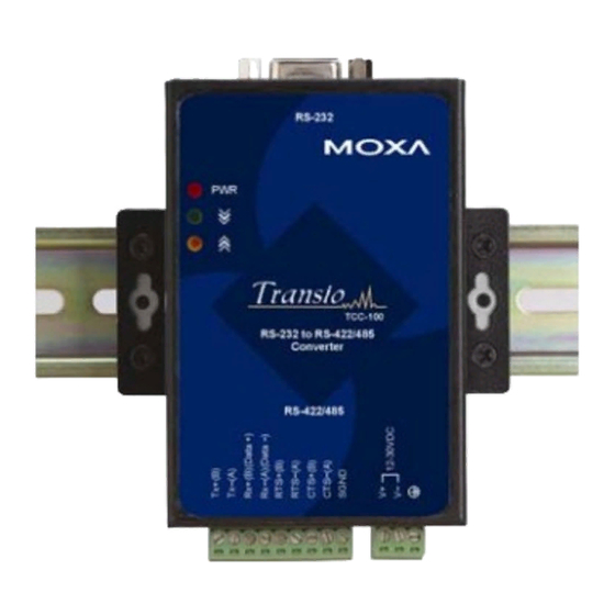
Introduction C h a p t e r TCC-100/100I is an RS-232 to RS-422/485 media converter. Note that TCC-100I comes with 2 KV isolation protection. The following topics are covered in this chapter: Overview Product Features Package Checklist Product Specifications... -
Page 6: Overview
Moxa TCC-100/100I User’s Guide Overview Introduction Many important devices used in today’s industrial environment are still designed for use with an RS-232 interface. The reason is due in part to tradition, and in part to convenience. RS-232 hardware is relatively easy to design, and the device can be readily connected to most PCs. - Page 7 Introduction RTS/CTS RS-422 Handshaking Signals TCC-100/100I provides RS-422 handshaking signal support. The RTS and CTS signals help solve the RS-422 signal handshaking problem and reduce data transmission errors. Built-in RS-485 ADDC™ Intelligence ADDC™ (Automatic Data Direction Control), a Moxa leading technology, uses a clever hardware solution to manage RS-485’s data flow control problem.
-
Page 8: Product Features
• 2 KV Isolation (TCC-100I) for both power and RS-422/485 signals • Operating temperature from -20°C to 60°C Package Checklist Before installing Moxa TCC-100/100I, verify that the package contains the following items: • TCC-100 or TCC-100I • User’s Manual (this document) •... - Page 9 Introduction Storage Temperature -20 to 85°C (-4 to 185°F) Humidity 5 to 95 %RH Power Input Power Voltage External Power 12-30 VDC, Terminal Block Reverse Power Protects against V+/V- reversal Protection Over Current Protection Protects against 2 signals shorted together Power Consumption 400 mA (max.) at 12V Mechanical...
-
Page 10: Schematic
22 mm 67 mm 28.7 mm 43 mm O3.5 28.7 mm LED Indicators TCC-100/100I’s top panel contains three LED indicators, as described in the following table: LED Name LED Function Red indicates the power is on. GREEN Green indicates TCC-100/100I is... -
Page 11: Chapter 2 Installation
Installation Chapter 2 This chapter includes information about how to install TCC-100/100I, as well as function and block diagrams. The following topics are covered in this chapter: Hardware Installation Termination Resistor Diagram Function Diagram Isolation Block Diagram Typical Applications... -
Page 12: Hardware Installation
Moxa TCC-100/100I User’s Guide Hardware Installation Installing TCC-100/100I involves five straightforward steps: • STEP 1: Set the DIP Switches • STEP 2: Attach the Power Supply • STEP 3: Wire the Terminal Block • STEP 4: Attach the RS-232 Converter •... - Page 13 Installation Dip Switch Settings RS-422 Terminator active RS-422 4-wire RS-485 Terminator active 4-wire RS-485 2-wire RS-485 with Terminator 2-wire RS-485...
- Page 14 Moxa TCC-100/100I User’s Guide The newly implemented DIP-2 Switches are used to configure the pull high/low resistors for different applications. Pull High/Low Resistor DIP-2 SW1 DIP-2 SW2 150K (default) NOTE We recommend setting the pull high/low resistor to 1K (ON/ON)
- Page 15 NOTE: TCC-100/100I provides reverse power protection. I.e., it will automatically detect which power wire is negative, and which is positive. STEP 3: Wire the Terminal Block There are three wiring options available for connecting to TCC-100/100I’s RS-422/485 terminal block. 2-wire RS-485...
- Page 16 TCC-100/100I’s RS-422/485 terminal block directly to that network. Next, start HyperTerminal or Moxa Terminal Emulator, and then open a connection to both the COM port, and the port associated with TCC-100/100I’s RS-422/485 port. Simply type a few characters on your PC’s keyboard. The...
-
Page 17: Termination Resistor Diagram
Installation Termination Resistor Diagram Termination is designed to Termination Resistor: mitigate noise from the S3 On to Enable S3 Off to Disable RS-422/485 transmission signals. If the network cable is too long, undesirable transmission-line effects will RxD+ arise. The best method for mitigating energy on an unused RxD- conductor is to dissipate the... -
Page 18: Isolation Block Diagram
Typical Applications RS-485 Application A typical RS-485 application for TCC-100/100I is depicted in the following figure. In this scenario, two TCC-100I units are used to connect two PCs to an RS-485 network. The third TCC-100I is used to connect the PLC—which is designed for the RS-232 interface—to the RS-485 network. - Page 19 Installation RS-422 Application A typical RS-422 application for TCC-100/100I is depicted in the following figure. In this scenario, two TCC-100I units are used to create a point-to-point connection between a PC and Scales. The advantage of using two TCC-100I units to convert from RS-232, to RS-422, and then back to RS-232, is that the RS-422 cable connecting the two converters can be up to 1.2 km in length (this is quite an...
Need help?
Do you have a question about the TCC-100 and is the answer not in the manual?
Questions and answers