Moxa Technologies MiiNePort W1 Series User Manual
Hide thumbs
Also See for MiiNePort W1 Series:
- User manual (14 pages) ,
- Quick installation manual (4 pages) ,
- Quick installation manual (2 pages)

Related Manuals for Moxa Technologies MiiNePort W1 Series


Summary of Contents for Moxa Technologies MiiNePort W1 Series
- Page 1 MiiNePort W1 Series User’s Manual Edition 7.0, January 2020 www.moxa.com/product © 2020 Moxa Inc. All rights reserved.
- Page 2 MiiNePort W1 Series User’s Manual The software described in this manual is furnished under a license agreement and may be used only in accordance with the terms of that agreement. Copyright Notice © 2020 Moxa Inc. All rights reserved. Trademarks The MOXA logo is a registered trademark of Moxa Inc.
-
Page 3: Table Of Contents
Table of Contents Introduction ............................1-1 Overview ............................1-2 Package Checklist ..........................1-2 Product Features ..........................1-2 Panel Layout and Pin Assignments ....................2-1 MiiNePort W1 Dimensions ........................2-2 MiiNePort W1 Pin Assignments ......................2-3 MiiNePort W1-ST LED Indicators ......................2-4 Evaluation Board Layout ........................ - Page 4 MxNPortAPI Function Groups ........................ 8-3 Example Program ..........................8-3 Well-Known Port Numbers ........................ A-1 DIO Commands ..........................B-1 Serial Command Mode ........................C-1 Command/Reply Format ........................C-1 Overview Commands .......................... C-2 Basic Commands ..........................C-3 Network Commands ..........................C-4 WLAN Profile Commands ........................C-6 WLAN Security Commands ........................
-
Page 5: Introduction
Introduction The MiiNePort W1 series provides serial to 802.11 b/g embedded wireless solution with compact size, and ultra low power consumption features. Numerous operation modes are designed to fulfill the requirements of embedded module application. Complete driver support reduces software redesign effort and accelerate time to market. -
Page 6: Overview
Overview The MiiNePort W1 series is a very compact module that installs in a serial device to connect it to a wireless LAN. With such a small size, around half the size of a credit card, it can be installed into almost any kind of serial device. -
Page 7: Panel Layout And Pin Assignments
Panel Layout and Pin Assignments This chapter includes information about the panel layouts and pin assignments for MiiNePort W1 series. The layouts and reference circuit diagrams for the evaluation boards are also covered. The evaluation boards are used for evaluation and development of applications for MiiNePort W1 series. -
Page 8: Miineport W1 Dimensions
MiiNePort W1 Series Panel Layout and Pin Assignments MiiNePort W1 Dimensions Unit: mm (inch) -
Page 9: Miineport W1 Pin Assignments
MiiNePort W1 Series Panel Layout and Pin Assignments MiiNePort W1 Pin Assignments N.C. Eth_10M_LED PIO0 LTXD0 N.C. Eth_100M_LED PIO1 LRTS0 N.C. Eth_Rx+ PIO2 LDTR0 RDY_LED Eth_Rx- PIO3 LRXD0 FLT_LED Eth_center_tap PIO4 LCTS0 HW_RESET Eth_center_tap PIO5 LDSR0 SW_RESET Eth_Tx+ PIO6 LDCD0... -
Page 10: Miineport W1-St Led Indicators
MiiNePort W1 Series Panel Layout and Pin Assignments MiiNePort W1-ST LED Indicators Location Type Color Status Meaning Power is off. Unit is booting or rebooting. IP error condition occurs. Ready Steady On Unit is functioning normally. Green Unit is responding to software Locate function. -
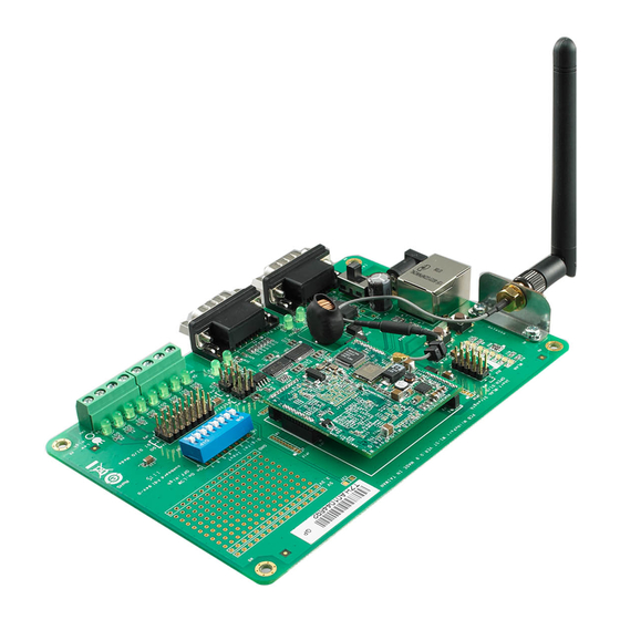
Page 11: Evaluation Board Layout
MiiNePort W1 Series Panel Layout and Pin Assignments Evaluation Board Layout Number Function HW Reset (Cold start) SW Reset (Reset to factory default) Ethernet RJ45 Connector Power Jack Power Switch DB9 Male Connector Serial Tx/Rx LED RS-232 and RS-485 2W Select Jumper... -
Page 12: Getting Started
Getting Started This chapter includes information about installing MiiNePort W1 series. The following topics are covered in this chapter: Wiring Requirements Installing onto the MiiNePort W1 Evaluation Board Circuit Pad Connecting to the Network Connecting the Power ... -
Page 13: Wiring Requirements
MiiNePort W1 Series Getting Started Wiring Requirements ATTENTION Before connecting the hardware, follow these important wiring safety precautions: Disconnect power source Do not install or wire this unit or any attached devices with the power connected. Disconnect the power before installation by removing the power cord before installing and/or wiring your unit. -
Page 14: Installing Onto The Miineport W1 Evaluation Board
Installing onto the MiiNePort W1 Evaluation Board The MiiNePort W1 evaluation board is a tool to help you develop your MiiNePort W1 series application. The module must first be installed on the board before the power supply, network, and serial device are connected. -
Page 15: Connecting To The Network
MiiNePort W1 Series Getting Started Connecting to the Network When developing your application, you may wish to use Ethernet to configure the MiiNePort W1, especially if your wireless LAN is not functional yet. You may connect to the network using the evaluation board’s RJ45 Ethernet port. - Page 16 MiiNePort W1 Series Getting Started 1. First, position the jumpers so they correspond with the input/output mode of each digital I/O channel. In the example below, channels 0 through 3 are output (DO) channels and channels 4 through 8 are input (DI) channels.
-
Page 17: Wlan Strength And Link Status Leds Circuit Design
MiiNePort W1 Series Getting Started WLAN Strength and Link status LEDs Circuit Design HD/1.27/M 1x10 DIP/180D GPIO1 WLAN_STR_LED4 GREEN_LED GPIO1 GPIO2 WLAN_STR_LED3 GREEN_LED GPIO2 GPIO3 WLAN_STR_LED2 GREEN_LED GPIO3 GPIO4 WLAN_STR_LED1 GREEN_LED GPIO4 GPIO5 WLAN_STR_LED0 GREEN_LED GPIO5 WLAN_Link_LED GREEN_LED HEADER Short for WLAN Strength LED NOTE For more information on circuit design, please refer to the MiiNePort W1 Schematic Design Guide. -
Page 18: Selecting An Operation Mode
Selecting an Operation Mode In this section, we describe the available operation modes for the MiiNePort W1. There is a mode that relies on a driver installed on the host computer, and other modes that rely on TCP/IP socket programming concepts. -
Page 19: Overview
Selecting an Operation Mode Overview The MiiNePort W1 series connects serial devices to the wireless LAN. It has a built-in TCP/IP stack that saves you the effort of programming networking protocols. Simply select the proper operating mode to allow your computer to access, manage, and configure your serial device over the Internet. -
Page 20: Udp Mode
Real COM mode allows you to continue using your serial communications software to access devices that are now attached to the MiiNePort W1 series module. On the host, the Real COM driver automatically intercepts data sent to the COM port, packs it into a TCP/IP packet, and redirects it to the network. At the other end of the connection, the MiiNePort W1 series accepts the Ethernet frame, unpacks the TCP/IP packet, and sends the serial data to the appropriate device. -
Page 21: Initial Ip Address Configuration
Initial IP Address Configuration When setting up your MiiNePort W1 series module for the first time, the first thing you should do is configure the IP address. This chapter introduces the methods that can be used to configure the MiiNePort W1 series’... -
Page 22: Selecting An Ip Address Or Configuration
MiiNePort W1 Series Initial IP Address Configuration ATTENTION Please refer to active interface . (chapter 7) Selecting an IP Address or Configuration For most applications, you will assign a fixed IP address to the module, which means that you set the IP address directly. -
Page 23: Assigning Ip Address With Telnet Console
Depending on how your computer and network are configured, you may find it convenient to use network access to set up your MiiNePort W1 series module’s IP address. This can be done using the Telnet program. 1. Select Run… from the Windows Start menu. - Page 24 MiiNePort W1 Series Initial IP Address Configuration 4. Select Network by pressing N or by using the cursor keys. Press ENTER after making the selection. 5. Select Ethernet or WLAN and press ENTER. 6. Use the cursor keys to navigate between the different fields. For IP address, Netmask, and Gateway, enter the desired values directly.
- Page 25 MiiNePort W1 Series Initial IP Address Configuration 8. Select Restart and then press ENTER. 9. Select System and then press ENTER. 10. Press Enter to restart the module. It will reboot with the new IP settings.
-
Page 26: Utility Console And Driver Installation
Utility Console and Driver Installation This chapter describes the installation of utilities and drivers, which are used to perform simple configurations and driver installations The following topics are covered in this chapter: Device Search Utility Installing Device Search Utility ... -
Page 27: Device Search Utility
MiiNePort W1 Series Utility Console and Driver Installation Device Search Utility Installing Device Search Utility 1. Click the setup file that can be downloaded from the MiiNePort’s product page on Moxa’s website to install the Device Search Utility. Once the program starts running, click Yes to proceed. -
Page 28: Device Search Utility Configuration
MiiNePort W1 Series Utility Console and Driver Installation 5. The installer will display a summary of the installation options. Click Install to begin the installation. The setup window will report the progress of the installation. To change the installation settings, click Back and navigate to the previous screen. - Page 29 MiiNePort W1 Series Utility Console and Driver Installation NOTE Users running Windows Vista and Windows 7 will see a “User Account Control” popup and should allow the program. 2. The Searching window indicates the progress of the search. 3. When the search is complete, all MiiNePort modules that were located will be displayed in the Device Search Utility window.
-
Page 30: Nport Windows Driver Manager
MiiNePort W1 Series Utility Console and Driver Installation NPort Windows Driver Manager Installing NPort Windows Driver Manager NPort Windows Driver Manager is intended for use with serial ports that are set to Real COM mode. The software manages the installation of drivers that allow you to map unused COM ports on your PC to your device through the MiiNePort’s serial port. - Page 31 MiiNePort W1 Series Utility Console and Driver Installation 4. Click Next to install the program’s shortcuts in the appropriate Start Menu folder. 5. The installer will display a summary of the installation options. Click Install to begin the installation. The setup window will report the progress of the installation.
-
Page 32: Using Nport Windows Driver Manager
MiiNePort W1 Series Utility Console and Driver Installation Using NPort Windows Driver Manager After you install NPort Windows Driver Manager, you can set up the MiiNePort’s serial port, which is connected to your device’s main board, as remote COM ports for your PC host. Make sure that the serial port on your MiiNePort is already set to Real COM mode when mapping COM ports with the NPort Windows Driver Manager. - Page 33 MiiNePort W1 Series Utility Console and Driver Installation 4. Alternatively, you can select Input Manually and then manually enter the MiiNePort module’s IP Address, 1st Data Port, 1st Command Port, and Total Ports to which COM ports will be mapped.
-
Page 34: The Linux Real Tty Driver
MiiNePort W1 Series Utility Console and Driver Installation The Linux Real TTY Driver 1. Obtain the driver file from Moxa’s website, at http://www.moxa.com. 2. Log in to the console as a super user (root). 3. Execute cd / to go to the root directory. -
Page 35: Removing Mapped Tty Ports
MiiNePort W1 Series Utility Console and Driver Installation Removing Mapped TTY Ports After logging in as root, enter the directory /usr/lib/npreal2/driver and then execute mxdelsvr to delete a server. The syntax of mxdelsvr is: mxdelsvr [IP Address] Example: # cd /usr/lib/npreal2/driver # ./mxdelsvr 192.168.3.4... -
Page 36: Configuring The Unix Driver
MiiNePort W1 Series Utility Console and Driver Installation 4. Compile and Link For SCO UNIX: # make sco For UnixWare 7: # make svr5 For UnixWare 2.1.x, SVR4.2: # make svr42 Configuring the UNIX Driver Modify the configuration: The configuration used by the moxattyd program is defined in the text file moxattyd.cf, which is in the same directory that contains the program moxattyd. -
Page 37: Web Browser Settings
MiiNePort W1 Series Utility Console and Driver Installation 2. Find the process ID (PID) of the program moxattyd. # ps -ef | grep moxattyd 3. Update configuration of the moxattyd program. # kill -USR1 [PID] (e.g., if moxattyd PID = 404, kill -USR1 404) -
Page 38: Navigating The Web Console
MiiNePort W1 Series Utility Console and Driver Installation ATTENTION If you are not using Internet Explorer, cookies are usually enabled through a web browser setting such as “allow cookies that are stored on your computer” or “allow per-session cookies.” Cookies are used for password transmission only. - Page 39 MiiNePort W1 Series Utility Console and Driver Installation ATTENTION You may use Web Console to export the configuration file when you have finished configuring the module. This way, you can restore your settings if you need to reset the module. Please refer to Chapter 9 for additional information about using the Export and Import functions.
-
Page 40: Web Console Configuration
Web Console Configuration The web console is the most user-friendly method available to configure your MiiNePort module. This chapter introduces the web console function groups and function definitions. The following topics are covered in this chapter: Basic Settings Network Settings ... -
Page 41: Basic Settings
MiiNePort W1 Series Web Console Configuration Basic Settings On the Basic Settings page, you can configure Server name, Server location, Time zone, Local time, and Time server. Server Name Default Options free text (e.g., “Server 1”) Description This is an optional free text field to help you differentiate one module from another. It does not affect operation of the module. -
Page 42: Network Settings
IP address. When the IP address is received from the DNS server, the user’s computer uses that information to connect to the website’s web server. The MiiNePort W1 series will play the role of a DNS client, actively querying the DNS server for the IP address associated with a particular domain name. - Page 43 On the Ethernet Settings page in the Network Settings folder, you can modify IP configuration, IP address, Netmask, Gateway, and Speed. You must assign a valid IP address to the MiiNePort W1 series before it will work in your network environment. Your network system administrator should provide you with an IP address and related settings for your network.
- Page 44 Consult your network administrator if you do not know how to set this parameter. ATTENTION In dynamic IP environments, the MiiNePort W1 series will send 3 requests every 30 seconds to the DHCP or BOOTP server until the network settings have successfully been assigned. The first request will time out after one second;...
- Page 45 The WLAN page is located under WLAN Settings in the Network Settings folder. You can modify IP configuration, IP address, Netmask, and Gateway for your WLAN. The MiiNePort W1 series support IEEE 802.11b/g wireless network interfaces. The supported IP configurations are static and dynamic (BOOTP, DHCP, or BOOTP+DHCP). Users can set up the IP configuration with the Web/Telnet consoles through the MiiNePort W1 series’...
- Page 46 The Profile page is located under WLAN Settings in the Network Settings folder. This is where you configure the MiiNePort W1 series for Ad-hoc or Infrastructure operation. Different settings are available depending on whether you select Ad-hoc Mode or Infrastructure Mode.
- Page 47 Infrastructure Mode, Ad-hoc Mode Description This field specifies whether the MiiNePort W1 series will operate in Ad-hoc or Infrastructure Mode. For all wireless networking devices, there are two possible modes for communication with another wireless device. Devices that are configured for Ad-hoc Mode automatically detect and communicate directly with each other and do not require a wireless access point (AP) or gateway.
- Page 48 MiiNePort W1 Series Web Console Configuration General Settings for WLAN Profile The General page is opened through the Profile page, under WLAN Settings in the Network Settings folder. After selecting Ad-hoc or Infrastructure Mode, click General to view or modify the general properties for that profile.
- Page 49 MiiNePort W1 Series Web Console Configuration In Infrastructure Mode On the General page, you can configure Profile name and SSID. Additional settings are also available depending on whether you select Ad-hoc Mode or Infrastructure Mode. Profile Name Default Ad-hoc (in Ad-hoc Mode)
- Page 50 MiiNePort W1 Series Web Console Configuration Channel Default Options 1,2,3,4,5,6,7,8,9,10,11 Description This field is for Ad-Hoc Mode only and specifies the radio channel to use for the wireless network. In Infrastructure Mode, the AP specifies the channel automatically. Security Settings for WLAN Profile The Security page is opened through the Profile page, under WLAN Settings in the Network Settings folder.
- Page 51 MiiNePort W1 Series Web Console Configuration You will need to configure Authentication and Encryption. These settings must match the settings on the wireless device at the other end of the connection (such as the AP). Different settings and options are available depending on how Authentication and Encryption are configured.
- Page 52 Description This field specifies how wireless devices will be authenticated. Only authenticated devices will be allowed to communicate with the MiiNePort W1 series. If a RADIUS server is used, this setting must match the setting on the RADIUS server. Open System: The MiiNePort W1 series will simply announce a desire to associate with another station or access point.
- Page 53 MiiNePort W1 Series Web Console Configuration Encryption Default Disable Options Disable, WEP Description This field specifies the type of encryption to use during wireless communication. Different encryption methods are available depending on the Authentication setting. Also, each encryption method has its own set of parameters that may also require configuration.
- Page 54 MiiNePort W1 Series Web Console Configuration WEP Key 1 Through 4 Default Options free text in ASCII or HEX Description These fields are only available if WEP key source is set to “Manual”. Enter each WEP key in ASCII or HEX as specified in WEP key format. The number of characters required for each key depends on WEP key length and WEP key format.
- Page 55 MiiNePort W1 Series Web Console Configuration Default Disable Options Disable, Enable Description This field is only available in Infrastructure Mode and is used to specify the MiiNePort W1 roaming behavior. Roaming is the ability to connect to different APs so wireless communication is not confined to one area or one particular AP.
- Page 56 MiiNePort W1 Series Web Console Configuration Gratuitous ARP Default Disabled Options Disabled, Enabled (default value: 300 sec.) Description This field specifies how often the MiiNePort W1/MiiNePort W1-T sends broadcast packets to update the ARP table. This may be required for certain applications.
-
Page 57: Serial Port Settings
MiiNePort W1 Series Web Console Configuration Serial Port Settings The Operation Modes page is where you configure the serial port’s operation mode and related settings. For an introduction to the different operation modes, please refer to Chapter 4. Operation Modes Before reading this section, refer to Chapter 3: Choosing the Proper Operation Mode to select the operation mode that best fits your device application. - Page 58 MiiNePort W1 Series Web Console Configuration Real COM Mode ATTENTION To use Real COM mode, refer to Chapter 6: Utility Console and Driver Installation for instructions on how to install the Real COM driver on Windows or Linux machines. TCP alive check time...
- Page 59 MiiNePort W1 Series Web Console Configuration Ignore jammed IP Setting Factory Default Necessity Enable, Disable Disable Required when Max connection is greater than 1 This option determines how the port will proceed if multiple hosts are connected and one or more of the hosts stops responding as the port is transmitting data.
- Page 60 MiiNePort W1 Series Web Console Configuration ATTENTION Delimiter 2 is optional. If left blank, then Delimiter 1 alone trips clearing of the buffer. If the size of the serial data received is greater than 1 KB, the MiiNePort will automatically pack the data and send it to the Ethernet.
- Page 61 MiiNePort W1 Series Web Console Configuration RFC 2217 Mode TCP alive check time Setting Factory Default Necessity 0 to 99 min 7 min Optional 0 min: TCP connection is not closed due to an idle TCP connection. 1 to 99 min: The MiiNePort automatically closes the TCP connection if there is no TCP activity for the given time.
- Page 62 MiiNePort W1 Series Web Console Configuration Use Delimiter 1 to define the first delimiter character in hex. If only one delimiter character is used, Delimiter 2 should be set to “0”. If the delimiter is a two-character sequence, use Delimiter 2 to define the second character.
- Page 63 MiiNePort W1 Series Web Console Configuration ATTENTION If you want to send a series of characters in the same packet, the serial device attached to the MiiNePort should send that series of characters during a time interval less than the Force transmit timeout for the MiiNePort, and the total length of data must be less than or equal to the MiiNePort’s internal buffer size.
- Page 64 MiiNePort W1 Series Web Console Configuration ATTENTION The Inactivity time should be greater than the Force transmit timeout. To prevent the unintended loss of data due to the session being disconnected, it is highly recommended that this value is set large enough so that the intended data transfer is completed.
- Page 65 MiiNePort W1 Series Web Console Configuration Local TCP port Setting Factory Default Necessity 1 to 65535 4001 Required The Local TCP port is the TCP port that the MiiNePort uses to listen to connections, and that other devices must use to contact the MiiNePort. To avoid conflicts with well known TCP ports, the default is set to 4001.
- Page 66 MiiNePort W1 Series Web Console Configuration Do Nothing, Do Nothing Optional Delimiter + 1, Delimiter + 2, Strip Delimiter The Delimiter process field determines how the data is handled when a delimiter is received. Delimiter 1 must be enabled for this field to have effect. If Delimiters 1 and 2 are both enabled, both characters must be received for the delimiter process to take place.
- Page 67 MiiNePort W1 Series Web Console Configuration TCP Client Mode TCP alive check time Setting Factory Default Necessity 0 to 99 min 7 min Optional 0 min: The TCP connection is not closed due to an idle TCP connection. 1 to 99 min: The module automatically closes the TCP connection if there is no TCP activity for the given time.
- Page 68 MiiNePort W1 Series Web Console Configuration ATTENTION Inactivity time is ONLY active when “TCP connect on” is set to “Any character.” Ignore jammed IP Setting Factory Default Necessity Enable, Disable Disable Optional This option determines how the port will proceed if multiple hosts are connected and one or more of the hosts stops responding as the port is transmitting data.
- Page 69 MiiNePort W1 Series Web Console Configuration Delimiter process Setting Factory Default Necessity Do Nothing, Do Nothing Optional Delimiter + 1, Delimiter + 2, Strip Delimiter The Delimiter process field determines how the data is handled when a delimiter is received. Delimiter 1 must be enabled for this field to have effect.
- Page 70 MiiNePort W1 Series Web Console Configuration ATTENTION The connection speed or throughput may be slow if one of the four connections is slow, since the 1 slow connection will slow down the other 3 connections. ATTENTION Both IP address and Domain Name can be used in the “Destination IP address” field.
- Page 71 MiiNePort W1 Series Web Console Configuration UDP Mode Destination IP address 1 Setting Factory Default Necessity IP address range Begin: Empty Required E.g., Begin: 192.168.1.1 End: Empty End: 192.168.1.10 Port: 4001 Destination IP address 2/3/4 Setting Factory Default Necessity IP address range...
- Page 72 MiiNePort W1 Series Web Console Configuration The Delimiter fields are used to specify a 1-character or 2-character sequence that acts as a marker to control packing of serial data. By default, delimiter characters are not defined, so the module transmits data as soon as it is received.
-
Page 73: Serial Parameter
MiiNePort W1 Series Web Console Configuration When set to 0, Force transmit is disabled, which means there is no time limit for how long the module will wait to receive data. When set between 1 and 65535, the module will pack data if serial data is not received in the specified time. - Page 74 MiiNePort W1 Series Web Console Configuration Data Bit Setting Factory Default Necessity 5, 6, 7, 8 Required Stop Bit Setting Factory Default Necessity 1, 1.5, 2 Required Stop Bits will be set to 1.5 when Data Bits is set to 5 bits.
-
Page 75: System Management
MiiNePort W1 Series Web Console Configuration System Management Misc. Network Settings Accessible IP List The Accessible IP List page is located under Misc. Network Settings in the System Management folder. This page is used this restrict access to the module by IP address. Only IP addresses on the list will be allowed access to the module. - Page 76 MiiNePort W1 Series Web Console Configuration SNMP Agent Settings The SNMP Agent page is located under Misc. Network Settings in the System Management folder. This page is used to configure the SNMP Agent on the MiiNePort W1/MiiNePort W1-T. SNMP: To enable the SNMP Agent function, select the Enable option, and enter a community name (e.g., public).
- Page 77 MiiNePort W1 Series Web Console Configuration Community String Default public Options free text (e.g., “public community”) Description This field specifies the community string used for the SNMP Agent. This is a text password mechanism that is used to weakly authenticate queries to agents of managed network devices.
-
Page 78: Auto Warning Settings
MiiNePort W1 Series Web Console Configuration Auto Warning Settings Serial Event Settings The Serial Event Settings page is located under Auto Warning Settings in the System Management folder. This is where you specify how the MiiNePort W1/MiiNePort W1-T will notify you of DCD and DSR events for each serial port. - Page 79 MiiNePort W1 Series Web Console Configuration E-mail Alert The E-mail Alert page is located under Auto Warning Settings in the System Management folder. This is where you specify how and where e-mail is sent for automatic notification of system and serial port events.
- Page 80 MiiNePort W1 Series Web Console Configuration SNMP Trap The SNMP Trap page is located under Auto Warning Settings in the System Management folder. This is where you specify the SNMP trap settings to use for automatic notification of system and serial port events.
-
Page 81: Maintenance
MiiNePort W1 Series Web Console Configuration Maintenance Console Settings The Console Settings page is located under Maintenance in the System Management folder. This is where you enable or disable access to the various module configuration consoles. You may modify HTTP console, HTTPS console, Telnet console, and SSH console. - Page 82 MiiNePort W1 Series Web Console Configuration Ping The Ping page is located under Maintenance in the System Management folder. It provides a convenient way to test an Ethernet connection or verify an IP address. Enter the IP address or domain name in the Destination field and click Activate.
- Page 83 MiiNePort W1 Series Web Console Configuration Configuration Import The Configuration Import page is located under Maintenance in the System Management folder. This is where you can load a previously saved or exported configuration. Select or browse for the configuration file in the Select configuration file field. If you also wish to import the IP configuration (i.e., IP address, netmask, and gateway), make sure that Import all configurations including IP configurations is checked.
- Page 84 MiiNePort W1 Series Web Console Configuration Load Factory Default The Load Factory Default page is located under Maintenance in the System Management folder. Click Submit to reset all settings to the factory defaults. You can preserve the module's existing IP settings (i.e., IP address, netmask, gateway, WLAN profile, and all certificates) by making sure Keep IP settings is checked before clicking Submit.
-
Page 85: System Settings
MiiNePort W1 Series Web Console Configuration ATTENTION If you forget the password, the ONLY way to configure the module is by loading the factory defaults with the reset button on the evaluation board. All settings will be lost. Before setting the password, you may want to first export the configuration to a file. Your configuration can then be easily imported back into the module if necessary. - Page 86 MiiNePort W1 Series Web Console Configuration Digital IO The Digital IO page is located under System Settings in the System Management folder. This is where you configure the 8 built-in DIO channels. DIO0 through DIO7 Default Input (Mode), Low (State)
-
Page 87: Certificate
MiiNePort W1 Series Web Console Configuration TCP Port Default 5001 Options 0 to 9999 Description This specifies the TCP port number that will be reserved for DIO commands. DIO commands may be used to control and obtain data from the module’s DIO channels. - Page 88 MiiNePort W1 Series Web Console Configuration WLAN SSL Certificate Import The WLAN SSL Certificate Import page is located under Certificate in the System Management folder. By default, the WLAN SSL certificate is automatically generated by the MiiNePort W1/MiiNePort W1-T based on the IP address of the wireless interface.
- Page 89 MiiNePort W1 Series Web Console Configuration The user certificate of the MiiNePort W1/MiiNePort W1-T must be installed in the RADIUS server when the MiiNePort W1/MiiNePort W1-T uses WPA (WPA2)/TLS. The trusted server certificate of the RADIUS server must also be installed in the MiiNePort W1/MiiNePort W1-T.
-
Page 90: System Monitoring
MiiNePort W1 Series Web Console Configuration Certificate/Key Delete The Certificate/Key Delete page is located under Certificate in the System Management folder. This page is where you can delete certificates or WPA keys that have been installed on the MiiNePort W1/MiiNePort W1-T. When you click Submit, any certificate or key that has been set to “Delete” will be deleted from the module. - Page 91 MiiNePort W1 Series Web Console Configuration Serial Port Status The Serial Port Status page is located under Serial Status in the System Monitoring folder. On this page, you can monitor the serial signal and data transmission status. TxCnt: number of Tx packets (to device) for the current connection...
-
Page 92: System Status
MiiNePort W1 Series Web Console Configuration Serial Port Settings The Serial Port Settings page is located under Serial Status in the System Monitoring folder. On this page, you can view the current serial communication settings. System Status Network Connections The Network Connections page is located under System Status in the System Monitoring folder. On this page, you can view the current status of any network connection to the MiiNePort W1/MiiNePort W1-T. - Page 93 MiiNePort W1 Series Web Console Configuration WLAN Status The WLAN Status page is located under System Status in the System Monitoring folder. This is where you can view the current WLAN settings and status. WLAN Site Survey The WLAN Site Survey page is located under System Status in the System Monitoring folder. This is where you can view live data on wireless signal strength and characteristics.
- Page 94 MiiNePort W1 Series Web Console Configuration Typical WLAN Site Survey Procedure 1. Download/install site survey software. 2. Run software on laptop. 3. Measure AP signal strength using software on laptop. Weakness • Signal strength is read from the laptop NIC...
-
Page 95: Restart
The Restart System page is located in the Restart folder. Click Submit to restart the MiiNePort W1 Series. Before restarting, be sure to save the configuration so the new settings will take effect upon restart. Configuration changes that have not been saved will be discarded when the MiiNePort W1 Series is restarted. -
Page 96: Restart Ports
MiiNePort W1 Series Web Console Configuration Restart Ports The Restart Ports page is located in the Restart folder. Select port 1 and click Submit to restart the serial port. 7-57... -
Page 97: Android Api Instructions
Android API Instructions The following topics are covered in this chapter: Overview How to Start MxNPortAPI MxNPortAPI Function Groups Example Program... -
Page 98: Overview
MiiNePort W1 Series Android API Instructions Overview If you want to remote control your serial devices on an Android platform, then the MxNPortAPI is a simple application programming tool that you can use. The MxNPortAPI helps programmers develop an Android application to access the device server by TCP/IP. -
Page 99: Mxnportapi Function Groups
MiiNePort W1 Series Android API Instructions For more details about the installation, please refer to the Overview section. MxNPortAPI Function Groups The supported functions in this API are listed below: Port Control Input/Output Port Status Inquiry Miscellaneous open read getBaud... - Page 100 MiiNePort W1 Series Android API Instructions byte[] buf = {'H','e','l','l','o',' ','W','o','r','l','d'}; mxNPort.open(); /*open port*/ mxNPort.setIoctlMode(mode); /*serial parameters setting*/ mxNPort.write(buf, buf.length); /*write data*/ mxNPort.close(); /*close port*/ } catch (MxException e){ /*Error handling*/ thread.start();...
-
Page 101: Well-Known Port Numbers
Well-Known Port Numbers This appendix is included for your reference. Listed below are Well Known Port Numbers that may cause network problems if you configure MiiNePort W1/MiiNePort W1-T for the same port. Refer to RFC 1700 for Well Know Port Numbers or refer to the following introduction from IANA. The port numbers are divided into three ranges: the Well Known Ports, the Registered Ports, and the Dynamic and/or Private Ports. - Page 102 MiiNePort W1 Series Well-Known Port Numbers UDP Socket Application Service reserved Management Utility Echo Discard Active Users (systat) Daytime Any private printer server Resource Location Protocol Host name server (names server) Whois (nickname) (Login Host Protocol) (Login) Domain Name Server (domain)
-
Page 103: Dio Commands
DIO Commands In this appendix, we present the DIO commands used to access the Digital I/O status of the MiiNePort W1/MiiNePort W1-T from an Ethernet network. The Digital I/O status can be accessed by a specific TCP port (default 5001) on the MiiNePort W1/MiiNePort W1-T. Command Packet Format Length (Bytes) 1 –... - Page 104 MiiNePort W1 Series DIO Commands char command; char version; /* This specification is version 2 */ char status; char length; } DIOHeaderStruct, *pDIOHeaderStruct; //define DIO Packet format //Used for Command and ACK packet typedef struct _DIO_Packet_Struct { DIOHeaderStruct header; char data[255];...
- Page 105 MiiNePort W1 Series DIO Commands data[2]: DIO status(hex), 0 for LOW, 1 for HIGH C code example: void WriteSingleDIO(int port, int mode, int status) DIOPacketStruct packet; packet.header.command = 2; // write single DIO command packet.header.version = 2; // DIO protocol version packet.header.length = 3;...
- Page 106 MiiNePort W1 Series DIO Commands 4. Writing Multiple DIOs Parameters: Command code: 6(hex) Version: 2(hex) Command status: doesn’t matter Length of data: (end-start+1)*2 + 2 data[0]: Number of the DIO you wish to access first. data[1]: The last number of the DIO you wish to access...
-
Page 107: Serial Command Mode
Serial Command Mode Command/Reply Format Single Line Command Format Head Parameters Tail 1 byte 1 byte 2 bytes 0 to n bytes 1 or 2 bytes Single Line Reply Format Head Parameters Tail 1 byte 1 byte 2 bytes 0 to n bytes 1 or 2 bytes Head and Tail Head... -
Page 108: Overview Commands
MiiNePort W1 Series Serial Command Mode Restriction The total number of parameters in a single command cannot exceed 1024 characters. Overview Commands Command Name Parameter Example Description Code Code System requests MiiNePort’s serial View ?G@S number. Serial MiiNePort reports serial number is... -
Page 109: Basic Commands
MiiNePort W1 Series Serial Command Mode Basic Commands Command Name Parameter Example Description Code Code System requests configured device ?GBN name for this MiiNePort !GBN0MiiNePo MiiNePort reports device name as Device rt_W1_Office ‘MiiNePort_W1_Office’. Name ?SBNMiiNePort System sets the device name as _W1_Office ‘MiiNePort_W1_Office’. -
Page 110: Network Commands
MiiNePort W1 Series Serial Command Mode Network Commands Command Name Parameter Example Description Code Code System requests DNS server 1 ?GND1 The index (1 or 2) of DNS address for this MiiNePort. server. !GND0192.16 MiiNePort reports DNS server 1 DNS Server IP 8.1.2... - Page 111 MiiNePort W1 Series Serial Command Mode Command Name Parameter Example Description Code Code MiiNePort reports command !SNG0 executed successfully. System requests WLAN IP ?GWC configuration for this MiiNePort. "MiiNePort’s WLAN IP configuration index as shown in the following MiiNePort reports WLAN IP...
-
Page 112: Wlan Profile Commands
MiiNePort W1 Series Serial Command Mode WLAN Profile Commands Command Name Parameter Example Description Code Code System requests WLAN profile ?GPN network type. "MiiNePort’s WLAN network type index as shown in the This WLAN profile network type is following table: !GPN01 'Infrastructure Mode'. -
Page 113: Wlan Security Commands
MiiNePort W1 Series Serial Command Mode Command Name Parameter Example Description Code Code The index (1 ~ 3) and fast roaming scan System sets the fast roaming scan ?STH1;10 channels(0~14), separated channel 1 to '10'. by a semicolon (;). MiiNePort reports write command !STH0 executed successfully. - Page 114 MiiNePort W1 Series Serial Command Mode Command Name Parameter Example Description Code Code "(0)adhoc/(1)infra, encryption index. Parameters are separated by a semicolon (;). System sets the adhoc mode's ?SQE0;2 1: Disable encryption to 'WEP' 2: WEP 3: TKIP 4: AES-CCMP...
- Page 115 MiiNePort W1 Series Serial Command Mode Command Name Parameter Example Description Code Code 0 (adhoc) or 1 (infrastructure) System requests the adhoc mode's ?GQF0 MiiNePort’s network key format. type . "The index of Key format: The adhoc mode's key format is...
- Page 116 MiiNePort W1 Series Serial Command Mode Command Name Parameter Example Description Code Code "The index of EAP method: 1: TLS The infrastructure mode's EAP !GQP01 2: PEAP method is 'TLS'. 3: TTLS 4: LEAP "(1)infra, EAP method index. Parameters are separated by a semicolon (;).
- Page 117 MiiNePort W1 Series Serial Command Mode Command Name Parameter Example Description Code Code Only support 1 (infrastructure) MiiNePort’s network type and (1)user System requests the infrastructure ?GQU1;1 name/(2)anonymous mode's user name. username. Parameters are separated by a semicolon (;). MiiNePort's WPA...
-
Page 118: Advanced Commands
MiiNePort W1 Series Serial Command Mode Advanced Commands Command Name Parameter Example Description Code Code System requests gratuitous ?GVA ARP status for alert mail server. Reply parameters: 1 and send MiiNePort reports gratuitous period if gratuitous ARP is !GVA01;300 ARP as ‘Enable’ and send period enabled;... -
Page 119: Opmode Commands
MiiNePort W1 Series Serial Command Mode OPMode Commands Command Name Parameter Example Description Code Code Two numbers separated by a System requests for port 1’s semicolon (;) denote port index Operation Mode for this and MCSC channel index. For ?GOM1;0 MiiNePort. - Page 120 MiiNePort W1 Series Serial Command Mode Command Name Parameter Example Description Code Code Reply parameters: MiiNePort’s MiiNePort reports maximum TCP maximum connection !GRM04 connection number as ‘4’. number. Port index, MCSC channel index, and maximum connection System sets maximum number. Parameters are ?SRM1;0;4...
- Page 121 MiiNePort W1 Series Serial Command Mode Command Name Parameter Example Description Code Code Port index, and MCSC channel index. Every parameter is System sets port 1’s TCP alive separated by semicolon (;). For ?SFA1;0;5 check time as ‘5’ for port 1.
- Page 122 MiiNePort W1 Series Serial Command Mode Command Name Parameter Example Description Code Code Two numbers separated by a semicolon (;) denote port index System requests maximum and MCSC channel index. For an ?GTM1;0 connection number for port 1. MCSC-disabled port, the channel index is 0.
- Page 123 MiiNePort W1 Series Serial Command Mode Command Name Parameter Example Description Code Code MiiNePort reports TCP port as Reply parameters: TCP port !GTP04001 ‘4100’. Port index, MCSC channel index, and TCP local port. Every parameter is separated by ?STP1;0;4 System sets TCP port as ‘4100’...
- Page 124 MiiNePort W1 Series Serial Command Mode Command Name Parameter Example Description Code Code Two numbers separated by a semicolon (;) denotes port index System requests for TCP client and MCSC channel index. For ?GTL1;0 local port setting for port 1.
-
Page 125: Data Packing Commands
MiiNePort W1 Series Serial Command Mode Command Name Parameter Example Description Code Code Three numbers separated by a semicolon (;) denote port index, MCSC channel index, and System requests UDP destination ?GUD1;0;3 destination address index from address 3 for port 1. - Page 126 MiiNePort W1 Series Serial Command Mode Command Name Parameter Example Description Code Code Port index, MCSC channel index, and data packing length to set. Parameters are separated by a ?SOL1;0; System sets port 1’s data semicolon (;). For an MCSC- packing length as ‘256’.
-
Page 127: Port Parameter Commands
MiiNePort W1 Series Serial Command Mode Command Name Parameter Example Description Code Code Port index, MCSC channel index, and force transmit timeout. Parameters are separated by a ?SOF1;0; System sets port 1’s force semicolon (;). For an MCSC- transmit timeout as ‘5’ (ms). - Page 128 MiiNePort W1 Series Serial Command Mode Command Name Parameter Example Description Code Code System requests port 1’s Stop bits ?GSS1 Port index. for this MiiNePort. !GSS00 MiiNePort reports Stop bits as ‘1’. "Port index and stop bits separated by a semicolon Port Stop (;).
-
Page 129: Misc Network Commands
MiiNePort W1 Series Serial Command Mode MISC Network Commands Comman Name Parameter Example Description d Code System requests ?GAS Enable/Disable accessible IP list for this MiiNePort. MiiNePort reports accessible IP Enable/Disabl !GAS01 list as ‘Enable’. e Accessible IP List System sets accessible IP list... - Page 130 MiiNePort W1 Series Serial Command Mode Comman Name Parameter Example Description d Code MiiNePort reports command !SML0 executed successfully. System requests SNMP read ?GMU community string for this MiiNePort. MiiNePort reports SNMP read !GMU0public SNMP Read community string as ‘public’.
- Page 131 MiiNePort W1 Series Serial Command Mode Comman Name Parameter Example Description d Code "MiiNePort's SNMP read only or R/W user index and name string separated by a semicolon (;). The index of System sets the r/w user name ?SME1;rwuser this command as shown in to 'rwuser'.
- Page 132 MiiNePort W1 Series Serial Command Mode Comman Name Parameter Example Description d Code MiiNePort reports write !SMP0 command executed successfully. "The privacy mode index of this command as shown in the following: System requests the read only ?GMM0 0: Disable privacy mode.
-
Page 133: Auto Warning Commands
MiiNePort W1 Series Serial Command Mode Auto Warning Commands Command Name Parameter Example Description Code Code "The index of this command as shown in the following: System requests the mail ?GEC0 0: mail warning cold start setting. 1: trap" Enable (1) or Disable (0) - Page 134 MiiNePort W1 Series Serial Command Mode Command Name Parameter Example Description Code Code mail, enable/disable. System sets the mail warning Parameters are separated ?SEP0;1 password changed to 'Enable'. by a semicolon (;). MiiNePort reports write command !SEP0 executed successfully. "The index of this command...
- Page 135 MiiNePort W1 Series Serial Command Mode Command Name Parameter Example Description Code Code MiiNePort reports write command !SIU0 executed successfully. System requests the email ?GIP warning password. !GIP0warn The Email warning password is Email Warning password 'warnpassword'. Password ?SIPwarnp System sets the email warning...
-
Page 136: System Commands
MiiNePort W1 Series Serial Command Mode Command Name Parameter Example Description Code Code The MiiNePort's trap ?SMCtrapc System sets the trap community community string to 'trapcom'. MiiNePort reports write command !SMC0 executed successfully. System Commands Command Name Parameter Example Description... - Page 137 MiiNePort W1 Series Serial Command Mode Command Name Parameter Example Description Code Code Reply parameters: 0 if serial MiiNePort reports serial command mode can be triggered command mode can only be !GCB01 at any time, or 1 if it can only be triggered by characters at triggered at boot up.
- Page 138 MiiNePort W1 Series Serial Command Mode Command Name Parameter Example Description Code Code Reply parameters: 1 (high) or 0 (low), note that this function is MiiNePort reports DIO0’s !GPS00 configuration only if specific DIO initial state is ‘low’. port is set to initial output.
- Page 139 MiiNePort W1 Series Serial Command Mode Command Name Parameter Example Description Code Code A single minus symbol indicates the target host did not reply in 1000 milliseconds. Otherwise, one ?CNP192.1 System requests to PING decimal number indicating the 68.1.1 192.168.1.1.
-
Page 140: Miineport W1 Mib
MiiNePort W1 MIB overview basicSetting networkSetting modelName serverName dnsServer1IpAddr serialNumber serverLocation dnsServer2IpAddr firmwareVersion timeZone ethIpConfiguration ethIPAddress localTime ethIpAddress ethMacAddress timeServer ethNetMask wlanIPAddress ethDefaultGateway wlanMacAddress wlanIpConfiguration wlanSSID wlanIpAddress wlanNetworkType wlanNetMask wlanSecurityMode wlanDefaultGateway activeNetworkPort gratuitousArp upTime gratuitousArpSendPeriod serialCmdMode activeInterface serialPort1 profileSetting adhocProfile infrastructureProfile networkType adhocProfileName... - Page 141 MiiNePort W1 Series MiiNePort W1 MIB dataPacking sysStatus sysManagement portPacketLength remoteIpIndex enableAccessibleIpList portDelimiter1Enable monitorRemoteIp accessibleIpListIndex portDelimiter1 monitorTxCount activeAccessibleIpList portDelimiter2Enable monitorRxCount accessibleIpListAddress portDelimiter2 monitorTxTotalCount accessibleIpListNetmask portDelimiterProcess monitorRxTotalCount snmpEnable portForceTransmit monitorDSR snmpContactName monitorDTR snmpLocation comParamSetting monitorRTS mailWarningColdStart portAlias monitorCTS mailWarningWarmStart portInterface monitorDCD...
- Page 142 MiiNePort W1 Series MiiNePort W1 MIB opModeSetting realCOM Mode rfc2217 Mode portIndex realCOMTcpAliveCheck rfc2217TcpAliveCheck portMode realCOMMaxConnection rfc2217TcpPort realCOMIgnoreJammedIp realCOMAllowDriverControl realCOMConnectionDownRTS realCOMConnectionDownDTR tcpServer tcpClient tcpServerTcpAliveCheck tcpClientTcpAliveCheck udpDestinationAddress1Begin tcpServerInactivityTime tcpClientInactivityTime udpDestinationAddress1End tcpServerMaxConnection tcpClientIgnoreJammedIp udpDestinationPort1 tcpServerIgnoreJammedIp tcpClientDestinationAddress1 udpDestinationAddress2Begin tcpServerAllowDriverControl tcpClientDestinationPort1 udpDestinationAddress2End tcpServerTcpPort tcpClientDestinationAddress2...
Need help?
Do you have a question about the MiiNePort W1 Series and is the answer not in the manual?
Questions and answers