
Related Manuals for Moxa Technologies ioLogik E1261W-T


Summary of Contents for Moxa Technologies ioLogik E1261W-T
- Page 1 E1261W-T User’s Manual Edition 2.2, March 2017 www.moxa.com/product © 2017 Moxa Inc. All rights reserved.
- Page 2 E1261W-T User’s Manual The software described in this manual is furnished under a license agreement and may be used only in accordance with the terms of that agreement. Copyright Notice © 2017 Moxa Inc. All rights reserved. Trademarks The MOXA logo is a registered trademark of Moxa Inc.
-
Page 3: Table Of Contents
LED Indicators ..........................1-6 Initial Setup ............................2-1 Hardware Installation .......................... 2-2 Connecting the Power ........................2-2 Grounding the ioLogik E1261W-T ....................2-2 Connecting to the Network ......................2-2 I/O Wiring Diagrams ........................2-3 ioSearch™ Installation ......................... 2-4 Load Factory Default Settings ....................... 2-4 Using the Web Console ........................ - Page 4 Features of Active OPC Server ......................5-5 One Simple Click Creates Active Tags .................... 5-5 Faster, More Accurate Data Collection than Traditional “Pull Technology” ..........5-5 Dynamic IP Assignments for Cellular Remote IOs ................5-6 Active OPC Server Setup ........................5-6 Installing Active OPC Server ......................
-
Page 5: Introduction
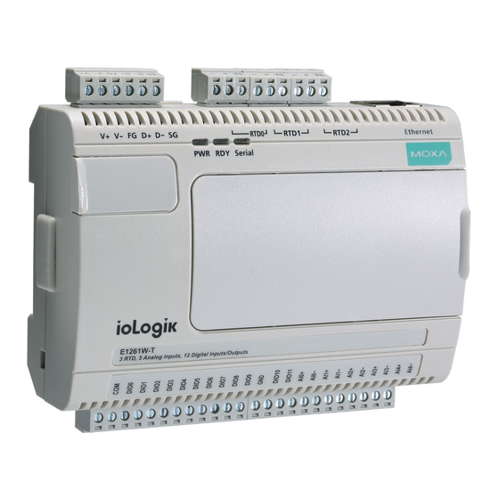
The Moxa ioLogik E1261W-T is designed for Ethernet-based remote condition monitoring systems. With 3 RTD, 5 AI, and 12 DIO channels, the ioLogik E1261W-T’s I/O combination is ideal for monitoring wind turbines and environmental conditions. Unlike other remote I/O products, which are passive and must poll for data, the ioLogik E1261W-T supports active communication with Moxa’s patented Active OPC Server to seamlessly... -
Page 6: Product Features
Wide operating temperature: -40 to 75°C (-40 to 167°F) • Supports SNMPv1/v2c Inside the Box The ioLogik E1261W-T is shipped with the following items: • ioLogik E1261W-T remote Ethernet I/O server NOTE: Notify your sales representative if any of the above items are missing or damaged. -
Page 7: Product Specifications
E1261W-T Introduction Product Specifications Inputs and Outputs Digital Inputs: 3 channels Analog Inputs: 5 channels Configurable DIOs: 12 channels Isolation: 3k VDC or 2k Vrms RTD Input Resolution: 16 bits Input Type: PT100 Accuracy: • ±0.1% FSR @ 25°C •... -
Page 8: Physical Dimensions
E1261W-T Introduction Ambient Relative Humidity: 5 to 95% (non-condensing) Serial Communication Interface: Data+, Data-, GND (3-contact terminal block) Serial Line Protection: 15 kV ESD for all signals Serial Communication Parameters Parity: None Data Bits: 8 Stop Bits: 1 Flow Control: None... -
Page 9: Hardware Reference
E1261W-T Introduction Hardware Reference Panel Guide NOTE The RESET button restarts the server and resets all settings to factory defaults. Use a pointed object such as a straightened paper clip to hold down the RESET button for 5 seconds. The factory defaults will be loaded once the READY LED turns green again. -
Page 10: Led Indicators
E1261W-T Introduction LED Indicators State Description Power System power is ON System power is OFF Green System is ready Blinking System in safe mode System is not ready Serial Serial port not connected Green Serial port connected Blinking Sending and receiving data... -
Page 11: Initial Setup
Initial Setup This chapter describes how to install the ioLogik E1261W-T. The following topics are covered in this chapter: Hardware Installation Connecting the Power Grounding the ioLogik E1261W-T Connecting to the Network I/O Wiring Diagrams ... -
Page 12: Hardware Installation
Initial Setup Hardware Installation Connecting the Power Connect the 12 to 36 VDC power line to the ioLogik E1261W-T’s terminal block (TB1). If power is properly supplied, the Power LED will glow a solid red color. ATTENTION Determine the maximum possible current for each power wire and common wire. Observe all electrical codes dictating the maximum current allowable for each wire size. -
Page 13: I/O Wiring Diagrams
E1261W-T Initial Setup I/O Wiring Diagrams A Dry Contact is a contact that does not provide voltage. A Wet Contact is a contact that will provide voltage when closed. -
Page 14: Iosearch™ Installation
Initial Setup ioSearch™ Installation ioSearch™ is a search utility that helps the user locate ioLogik E1261W-T devices on the local network. You may download the latest version of ioSearch from Moxa’s website. 1. Installing ioSearch™: Download the ioSearch™ utility from Moxa’s website, double click the installation file, and then follow the installation wizard’s instructions to complete the installation. -
Page 15: Using The Web Console
Using the Web Console The ioLogik E1261W-T’s main configuration and management utility is the built-in web console, which can be used to configure a wide range of options. The following topics are covered in this chapter: Introduction to the Web Console ... -
Page 16: Introduction To The Web Console
Submit button, your changes will not be retained. Submitted changes will not take effect until they are saved and the ioLogik E1261W-T is restarted! You may save and restart the server in one step by clicking on the Save/Restart button after you submit a change. -
Page 17: Overview
(see Chapter 3: AO Safe Mode Setting) or status (see Chapter 3: DO Safe Mode Setting) when the ioLogik E1261W-T cannot be controlled by a remote PC (such as in the event of a network failure). By default, the watchdog is disabled. Users can configure how each output channel responds... -
Page 18: Ethernet Configuration
LEDs for easier location of devices when troubleshooting. Ethernet Configuration On the Ethernet Configuration page, you can set up a static or dynamic IP address for the ioLogik E1261W-T, and configure the subnet mask and gateway address. User-Defined Modbus Addressing The input and output address can be configured in a different format on a specific settings page. -
Page 19: Default Modbus Address
ATTENTION Disable the user-defined Modbus addressing function if using the MXIO (.NET) library or Active OPC Server to control or monitor the ioLogik E1261W-T’s I/O status. Active OPC Server Settings Moxa’s Active OPC Server™ is a software package operated as an OPC driver of an HMI or SCADA system. It seamlessly connects Moxa’s ioLogik products to a wide variety of SCADA systems, including the most popular:... -
Page 20: Tag Generation
Using the Web Console Tag Generation Use the web console to create Active OPC (AOPC) tags for the ioLogik E1261W-T by opening your browser and navigating to the Active OPC Server Settings page. Follow these steps to create the tags and send them from the ioLogik E1261W-T to Active OPC Server: 1. -
Page 21: I/O Settings
E1261W-T Using the Web Console 5. On the Create AOPC Tag page, click on the Create Tags button to “push” tag configurations to the Active OPC Server utility. 6. Launch the Active OPC Server utility and the tags will be automatically created. Remember to save the configuration of the Active OPC Server when exiting the program. - Page 22 Safe Status Settings: For DI channels in Event Counter mode, you can configure whether or not counting starts or continues when Safe Status has been activated. When the network connection is lost, as specified in the Host Connection Watchdog, the ioLogik E1261W-T will start or stop the counter according to the channel’s Safe Status settings.
-
Page 23: Ai Channels
E1261W-T Using the Web Console AI Channels The current status of each AI (analog input) channel can be viewed on the AI Channel Settings page. Click on a specific AI channel to enable or disable it by selecting the Enable AI Channel field. There are two modes available for the AI channels: 1. -
Page 24: Ai Input Range
E1261W-T Using the Web Console 2. Current Mode Auto Scaling and Slope-intercept functions of the AI value can be defined on this page. AI Input Range Set the AI input ranges for each mode, as follows: 1. Voltage Mode (V) There is only one default analog Voltage input range: [0-10V] 2. - Page 25 E1261W-T Using the Web Console AI Input: Burn Out Mode Burn Out mode indicates when the Current AI has burned out. For example, the 4–20 mA Burn Out mode is defined in the following diagram: Users can define Burn Out (BO) values (default = 2 mA) for selected ranges. When input values are in the Burn Out range, raw data will register as 0000h to indicate that the analog input has burned out.
-
Page 26: Rtd Channels
Select the Enable RTD Channel checkbox and then select the sensor type from the dropdown menu that meets the physical attachment to the ioLogik E1261W-T. The ioLogik E1261W-T allows you to calibrate the temperature sensors. In each channel configuration section, follow the instructions and click Calibrate button to start the RTD sensor calibration. Each calibration requires around 30 seconds per channel. - Page 27 E1261W-T Using the Web Console The ioLogik E1261W-T allows you to manually adjust the current temperature reading. In each channel configuration section, select the channel, apply the offset value, and click the Submit button. 3-13...
-
Page 28: System Management
IP addresses. When the Enable the accessibility IP list checkbox is enabled, a host’s IP address must be provided and enabled in the list in order to gain access to the ioLogik E1261W-T. Enable access for a range of IP addresses by specifying the IP address and netmask, as follows: To allow access for a specific IP address Enter the IP address in the IP Address field and 255.255.255.255 in the Netmask field. -
Page 29: Network Connection
E1261W-T Using the Web Console Network Connection TCP connections from other hosts appear on the Network Connection page. This information can assist you with managing your devices. Firmware Update Load new or updated firmware onto the ioLogik from the Firmware Update page. -
Page 30: Export System Settings
ATTENTION If you forget the password, the ONLY way to configure the ioLogik E1261W-T is by using the Reset button to load the factory default settings. Before you set a password for the first time, it is a good idea to export the configuration file when you have finished setting up your ioLogik E1261W-T. -
Page 31: Load Factory Defaults
E1261W-T Using the Web Console Load Factory Defaults This function will reset all of the ioLogik E1261W-T’s settings to the factory default values. All previous settings, including the console password, will be lost. Save/Restart If you change the configuration, do not forget to reboot the system. -
Page 32: Using Iosearch
Using ioSearch™ This chapter describes ioSearch™, which is used to search for and locate ioLogik E1261W-T units. The following topics are covered in this chapter: Introduction to ioSearch™ ioSearch™ Main Screen Main Screen Overview ioSearch™ Setup ... -
Page 33: Introduction To Iosearch
E1261W-T Using ioSearch™ Introduction to ioSearch™ Moxa’s ioSearch™ utility is software tool that searches for ioLogik E1261W-T units on a physical network. The following functions are supported by the ioSearch™ utility: • Search for and locate ioLogik E1261W-T units •... -
Page 34: Iosearch™ Setup
E1261W-T Using ioSearch™ ioSearch™ Setup System Several operations are possible from the System menu. Auto Scan Active Ethernet I/O Servers will search for ioLogik servers on the network. When connecting for the first time or recovering from a network disconnection, you can use this command to find I/O servers that are on the network. -
Page 35: Sort
Locate an ioLogik E1261W-T Upgrade Firmware Import settings Export settings Unlock an ioLogik E1261W-T which is password protected Change IP Address of an ioLogik E1261W-T Main Function Right click on a particular ioLogik E1261W-T to view the ioSearch™ function menu. -
Page 36: Locate
Firmware Upgrade The ioLogik E1261W-T supports a remote firmware upgrade function. Enter the path to the firmware file or click on the icon to browse for the file. The wizard will lead you through the process until the server is restarted. -
Page 37: Import
“Shift” key, select “ioLogik”, and then right click. Export The export function is used to export the current configuration file of an ioLogik E1261W-T. The export file format will be ik12xx.txt where “xx” represents the model type of the ioLogik E1261W-T. -
Page 38: Change Ip Address
E1261W-T series devices, and is especially useful for first time installation. First, select the ioLogik E1261W-T device(s) you wish to modify. Then, right-click on the device(s) and select “Change IP Address” from the drop-down menu to open the Change IP Address window. After changing the IP address, click "Set"... -
Page 39: Restart System
Using ioSearch™ Restart System Select this command to restart the selected ioLogik E1261W-T. Restarting multiple ioLogik E1261W-T units is allowed. Select the ioLogik E1261W-T and right click to process this function. Reset to Default Select this function to reset all settings, including console password, to factory default values. -
Page 40: Mass Deployment (Import)
E1261W-T Using ioSearch™ Mass Deployment (Import) Users can import E1261-T series module information via ioSearch™. Select this command to reload a configuration from an exported .CSV file. Mass Deployment (Export) Users can export E1261-T series module information via ioSearch™. The export file format will be... -
Page 41: Active Opc Server
Active OPC Server Active OPC Server is a software package provided by Moxa that operates as an OPC driver for an HMI or SCADA system. It offers seamless connection from Moxa's ioLogik series products to SCADA systems, such as Wonderware, Citect, and iFix. Active OPC Server meets the latest standard of OPC DA 3.0, which allows connections to various kinds of devices and host OPC machines. -
Page 42: Introduction To Active Opc Server
OPC Server Specifications OPC Data Access 1.0a, 2.0, 2.05a, 3.0 Max. tags ioLogik Support Product Model ioLogik E1261W-T series, E2200 series, E4200, and W5300 series Firmware version V3.0 or above ioAdmin version V3.0 or above NOTE The latest versions are Active OPC Server V1.11 and ioAdmin 3.10. Use firmware V1.3 or above for the ioLogik W5312 series, V1.5 or above for the ioLogik W5340 series, and V1.2 or above for the ioLogik W5340-HSDPA... -
Page 43: Active Opc Server-From Pull To Push
E1261W-T Active OPC Server OPC Client/Server creates a common interface to connect to different devices Active OPC Server—From Pull to Push When looking up an I/O devices’ Modbus table, 19 or more steps are required to create a single tag. The steps include specifying the IP address, selecting the protocols, and defining the data type. - Page 44 E1261W-T Active OPC Server DI_1=ON DI_1=OFF DI_0=ON DI_0=OFF ioLogik Tag Update ioLogik Idle...
-
Page 45: Features Of Active Opc Server
E1261W-T Active OPC Server Features of Active OPC Server One Simple Click Creates Active Tags Moxa’s RTUs, remote I/O devices, and Active OPC Servers support automatic tag generation, which eliminates the headache of specifying individual target IP addresses, I/O channels, and data formats, while even eliminating any need for editing and importing configuration files. -
Page 46: Dynamic Ip Assignments For Cellular Remote Ios
E1261W-T Active OPC Server Dynamic IP Assignments for Cellular Remote IOs For most cellular solutions, each remote modem as well as the central SCADA server are assigned static public IPs when establishing bi-directional communication. Yet cellular network carriers charge higher monthly fees for static, public IPs than dynamic, private ones. -
Page 47: Main Screen Overview
E1261W-T Active OPC Server Main Screen Overview Active OPC Server Lite’s main screen displays a figure of the mapped iologik with the status of every I/O tag. Note that configuration and tags are not available until you set the ioLogik to create the tags. - Page 48 E1261W-T Active OPC Server System Several operations can be accessed from the System menu. Network Interface: Select which network to use if the PC has multiple network adaptors installed. Active Tag Listen Port: Select the preferred TCP socket port for tag generation from ioAdmin.
- Page 49 E1261W-T Active OPC Server System Log Settings: Enable or disable the Active OPC Server system log function. It will keep a Log file of all the Logging information. Launch DCOM Configuration: Launch the Windows DCOM configuration utility. Register OPC as Service: Force Active OPC Server to run as a Windows system service.
-
Page 50: Modbus/Tcp Default Address Mappings
Modbus/TCP Default Address Mappings The following topics are covered in this appendix: 0xxxx Read/Write Coils (Functions 1, 5, 15) 1xxxx Read only Coils (Support function 2) 3xxxx Read only Registers (Support function 4) 4xxxx Read/Write Registers (Support function 3,6,16) -
Page 51: 0Xxxx Read/Write Coils (Functions 1, 5, 15
E1261W-T Modbus/TCP Default Address Mappings NOTE The Modbus/TCP ID of the ioLogik E1261W-T is set to “1” by default. 0xxxx Read/Write Coils (Functions 1, 5, 15) Reference Address Data Type Description 00001 0x0000 1 bit CH0 DO Value 0: Off 1: On... - Page 52 E1261W-T Modbus/TCP Default Address Mappings Write: 1 : Clear counter value 0 : Return illegal data value(0x03) 00276 0x0113 1 bit CH3 DI Clear Count Value Read Always return:0 Write: 1 : Clear counter value 0 : Return illegal data value(0x03)
- Page 53 E1261W-T Modbus/TCP Default Address Mappings 04117 0x1014 1 bit CH4 DO Safe Value 0: Off 1: On 04118 0x1015 1 bit CH5 DO Safe Value 0: Off 1: On 04119 0x1016 1 bit CH6 DO Safe Value 0: Off 1: On...
- Page 54 E1261W-T Modbus/TCP Default Address Mappings 04611 0x1202 1 bit Reset CH2 AI Min Value Read: always 0 Write : 1: reset AI Min value 0: return Illegal Data Value 04612 0x1203 1 bit Reset CH3 AI Min Value Read: always 0...
- Page 55 E1261W-T Modbus/TCP Default Address Mappings 05646 0x160D 1 bit CH1 RTD Reset Maximum Value <R> Always 0 <W> 1=Reset to current value, 0=return illegal data value 05647 0x160E 1 bit CH2 RTD Reset Maximum Value <R> Always 0 <W> 1=Reset to current value,...
- Page 56 E1261W-T Modbus/TCP Default Address Mappings 08226 0x2021 1 bit CH1 DI Safe Mode Counter Operate Status 0: Stop 1: Start (R/W) 08227 0x2022 1 bit CH2 DI Safe Mode Counter Operate Status 0: Stop 1: Start (R/W) 08228 0x2023...
- Page 57 E1261W-T Modbus/TCP Default Address Mappings (R/W) CH11 DI Counter Trigger,0=Low to High, 1=High to Low 08252 0x203B 1 bit (R/W) 08257 0x2040 1 bit CH0 DI OverFlow Status Read : 0 : Normal ,1 : Overflow Write : 0 : Clear overflow status...
-
Page 58: 1Xxxx Read Only Coils (Support Function 2
E1261W-T Modbus/TCP Default Address Mappings Read/Wirte : 0 : Disable,1 : Enable 08275 0x2052 1 bit CH2 Power Off Storage Read/Wirte : 0 : Disable,1 : Enable 08276 0x2053 1 bit CH3 Power Off Storage Read/Wirte : 0 : Disable,1 : Enable... -
Page 59: 3Xxxx Read Only Registers (Support Function 4
E1261W-T Modbus/TCP Default Address Mappings 14610 0x1201 1 bit CH1 AI Mode 1: current(mA) , 0: Voltage(mV) (R) 14611 0x1202 1 bit CH2 AI Mode 1: current(mA) , 0: Voltage(mV) (R) 14612 0x1203 1 bit CH3 AI Mode 1: current(mA) , 0: Voltage(mV) (R) - Page 60 E1261W-T Modbus/TCP Default Address Mappings 30515 0x0202 1 word CH2 Read AI Value(RAW) 30516 0x0203 1 word CH3 Read AI Value(RAW) 30517 0x0204 1 word CH4 Read AI Value(RAW) 30521 0x0208 1 word CH0 Read AI Scaling Value Hi (float)
-
Page 61: 4Xxxx Read/Write Registers (Support Function 3,6,16
E1261W-T Modbus/TCP Default Address Mappings 34645 0x1224 1 word CH2 Read AI Min Scaling Value Hi (float) 34646 0x1225 1 word CH2 Read AI Min Scaling Value Low (float) 34647 0x1226 1 word CH3 Read AI Min Scaling Value Hi (float) - Page 62 E1261W-T Modbus/TCP Default Address Mappings 40017 0x0010 1 word CH0 DO Pulse Operate Status 0: Off 1: On 40018 0x0011 1 word CH1 DO Pulse Operate Status 0: Off 1: On 40019 0x0012 1 word CH2 DO Pulse Operate Status 0: Off 1: On...
-
Page 63: Network Port Numbers
Network Port Numbers ioLogik E1261W-T Network Port Usage Port Type Usage Web console service Modbus/TCP communication BOOTP/DHCP 4800 Auto search Export/import configuration file 9900 Active OPC Server 9950 Active OPC Server... -
Page 64: Factory Default Settings
Factory Default Settings ioLogik E1261W-T series products are configured with the following factory default settings: Default IP address 192.168.127.254 Default Netmask 255.255.255.0 Default Gateway 0.0.0.0 Communication watchdog Disable Modbus/TCP Alive Check Modbus/TCP Timeout Interval 60 sec DI Mode Filter time... -
Page 65: Fcc Interference Statement
FCC Interference Statement Federal Communication Commission Warning! This equipment has been tested and found to comply with the limits for a Class A digital device, pursuant to part 15 of the FCC Rules. Operation is subject to the following two conditions: (1) This device may not cause harmful interference, and (2) this device must accept any interference received, including interference that may cause undesired operation. -
Page 66: European Community (Ce
European Community (CE) This is a Class A product. In a domestic environment, this product may cause radio interference in which case the user may be required to take adequate measures.
Need help?
Do you have a question about the ioLogik E1261W-T and is the answer not in the manual?
Questions and answers