
Related Manuals for Moxa Technologies V2400 Series


Summary of Contents for Moxa Technologies V2400 Series
- Page 1 V2400 Series Expansion Modules User Manual Fifth Edition, November 2012 www.moxa.com/product © 2012 Moxa Inc. All rights reserved.
- Page 2 V2400 Series Expansion Modules User Manual The software described in this manual is furnished under a license agreement and may be used only in accordance with the terms of that agreement. Copyright Notice © 2012 Moxa Inc., All rights reserved.
-
Page 3: Table Of Contents
Table of Contents Introduction ............................1-1 Overview ............................1-2 Package Checklist ..........................1-2 Available Modules ..........................1-2 EPM-3338 Optional Accessories ..................... 1-2 EPM Module Specifications ........................1-2 EPM-3032 Specifications ......................1-2 EPM-3112 Specifications ......................1-3 EPM-3337 Specifications ......................1-3 EPM-3438 Specifications ......................1-5 EPM-3552 Specifications ...................... - Page 4 EPM-3338: Wi-Fi Module ......................4-32 EPM-3338: Cellular Module ......................4-33 EPM-3338: GPS Module ......................4-34 Windows System ..........................4-36 EPM-3032: Driver Installation......................4-36 EPM-3032: Configuring Serial Port Mode ..................4-38 EPM-3032: Changing the Software-Selectable UART Mode .............. 4-40 EPM-3438: Driver Installation......................4-41 EPM-3438: Programming Guide ....................
-
Page 5: Introduction
Introduction Moxa’s EPM series modules, which include modules with serial ports, a wireless/GPS card, a digital input/output channel card, a CAN bus card, a mini PCI/PCIe card, a VGA/DVI-I display card, and a 2-slot mini PCIe card, work with Moxa’s V2422 and V2426 embedded computers, giving end-users the ability to set up and expand a variety of industrial applications. -
Page 6: Overview
V2400 Series Expansion Modules Introduction Overview Moxa’s EPM series modules provide expansion options for V2422 and V2426 embedded computers. Modules may provide serial ports, combined Wi-Fi/GPS, a digital I/O channels, CAN bus interface, mini PCI/PCIe interfaces, combined VGA/DVI-I display, and a 2-slot mini PCIe card, giving end-users the ability to set up V2400 computers for a wide variety of industrial applications. -
Page 7: Epm-3112 Specifications
V2400 Series Expansion Modules Introduction RS-232: TxD, RxD, DTR, DSR, RTS, CTS, DCD, GND RS-422: TxD+, TxD-, RxD+, RxD-, GND RS-485-4w: TxD+, TxD-, RxD+, RxD-, GND RS-485-2w: Data+, Data-, GND Physical Characteristics Weight: 137 g Dimensions: 104 x 121 x 34 mm (4.09 x 4.76 x 1.34 in) Environmental Limits Operating Temperature: -40 to 70°C (-40 to 158°F) - Page 8 V2400 Series Expansion Modules Introduction WLAN Interface Supported Modes: • IEEE 802.11a/b/g/n for client/bridge mode • IEEE 802.11b/g/n for AP mode (Linux OS only) Standards: • IEEE 802.11a/b/g/n for Wireless LAN • IEEE 802.11i for Wireless Security Operating Channels (central frequency): •...
-
Page 9: Epm-3438 Specifications
V2400 Series Expansion Modules Introduction AP-only Protocols: ARP, BOOTP, DHCP, dynamic VLAN-Tags for 802.1X-Clients, STP/RSTP (IEEE 802.1D/w) Default Antenna: 2 dBi dual-band omni-directional antenna, RP-SMA (male) Connector for External Antennas: RP-SMA (female) Physical Characteristics Weight: 220 g Dimensions: 104 x 121 x 34 mm (4.09 x 4.76 x 1.34 in) Environmental Limits Operating Temperature: -25 to 55°C (-13 to 131°F), EN 50155 Class T1... -
Page 10: Epm-Dk02 Specifications
V2400 Series Expansion Modules Introduction USB 2.0 Bus SIM Card Holder: Reserved for Cellular applications Mini PCI Slot Interface: PCI Bus Frequency: 32-bit, 33 MHz PCI Physical Characteristics Weight: 117 g Environmental Limits Operating Temperature: -40 to 70°C (-40 to 158°F), EN 50155 Class TX... -
Page 11: Epm-3338 Specifications
V2400 Series Expansion Modules Introduction Dimensions: 104 x 121 x 34 mm (4.09 x 4.76 x 1.34 in) Environmental Limits Operating Temperature: -25 to 55°C (-13 to 131°F), EN 50155 Class T1 EPM-3338 Specifications PCI Express Mini Slot Interface 1: PCIExpress V1.0 (one lane) / USB 2.0 Interface 2: USB 2.0... - Page 12 V2400 Series Expansion Modules Introduction Modulation: • 802.11a: OFDM (BPSK, QPSK, 16-QAM, 64-QAM) • 802.11b: DSSS (DBPSK, DQPSK, CCK) • 802.11g: OFDM (BPSK, QPSK, 16-QAM, 64-QAM) • 802.11n: OFDM (BPSK, QPSK, 16-QAM, 64-QAM) • 802.11gn HT20: 17dBm ± 1.5dBm@MCS15 • 802.11gn HT40: 16dBm ± 1.5dBm@MCS15 •...
-
Page 13: Hardware Introduction
Hardware Introduction The EPM Series expansion modules are designed to work with Moxa’s V2422 and V2426 embedded computers. By providing different modules with different connectors, the EPM series offers the greatest flexibility and convenience for users who would like to easily establish industrial applications that require different communication interfaces. -
Page 14: Appearance
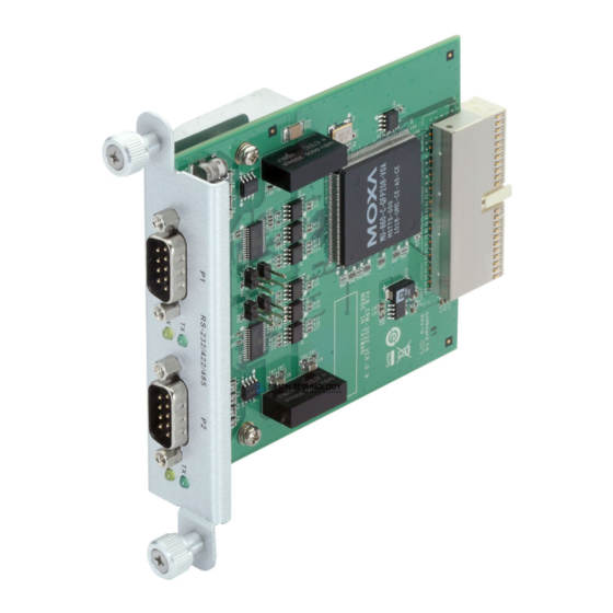
V2400 Series Expansion Modules Hardware Introduction Appearance EPM-3032 EPM-3112 EPM-3337 EPM-3438... - Page 15 V2400 Series Expansion Modules Hardware Introduction EPM-3552 EPM-DK01...
- Page 16 V2400 Series Expansion Modules Hardware Introduction EPM-DK02 EPM-3338...
- Page 17 V2400 Series Expansion Modules Hardware Introduction EPM-DK03...
- Page 18 V2400 Series Expansion Modules Hardware Introduction Dimensions All modules share the same dimensions.
-
Page 19: Hardware Connection Description
Hardware Connection Description In this chapter, we show how to connect the embedded computers to the network and to various devices. The following topics are covered in this chapter: Installing the EPM Expansion Modules Connecting Data Transmission Cables ... -
Page 20: Installing The Epm Expansion Modules
V2400 Series Expansion Modules Hardware Connection Description Installing the EPM Expansion Modules The EPM series expansion modules are designed to work with Moxa’s V2422 and V2426 embedded computers. Below we describe how to insert the modules into the embedded computer slots. -
Page 21: Epm-3337 Wireless/Gps Module
V2400 Series Expansion Modules Hardware Connection Description RS-232 RS-422 RS-485 RS-485 (4-wire) (2-wire) TxDA(-) TxDA(-) – TxDB(+) TxDB(+) – RxDB(+) RxDB(+) DataB(+) RxDA(-) RxDA(-) DataA(-) – – – – – – – – – EPM-3337 Wireless/GPS Module The EPM-3337 module comes with 4 connectors that can be used to connect antennas, including 2 Wi-Fi antennas, 1 cellular antenna, and 1 GPS antenna. -
Page 22: Epm-3112 Can Bus Module
V2400 Series Expansion Modules Hardware Connection Description EPM-3112 CAN Bus Module The EPM-3112 offers two CAN bus ports with DB9 male connectors. Use a cable to plug your CAN device into the module’s serial port. The pin assignments are shown in the following table:... - Page 23 V2400 Series Expansion Modules Hardware Connection Description D-Sub 15 Connector Pin Assignments Pin No. Signal Definitions GREEN BLUE – CRT_DETECT# – DDC_DATA HSYNC VSYNC – DVI-I Connector Pin Assignments Pin No. Signal Definition T.M.D.S. Data2- T.M.D.S. Data2+ T.M.D.S. Data2/4 Shield T.M.D.S.
-
Page 24: Epm-Dk02 Module: 2 Mini Pcie Sockets
V2400 Series Expansion Modules Hardware Connection Description EPM-DK02 Module: 2 mini PCIe Sockets The EPM-DK02 has two mini PCIe sockets that may be used for cellular communications expansion. The figures below show the slots’ specific locations. Note that while both sockets provide a mini PCIe interface, socket one supports either mini PCIe or USB 2.0 signals, whereas socket two only supports USB 2.0 signals. -
Page 25: Installing A Cellular Module
V2400 Series Expansion Modules Hardware Connection Description Installing a Cellular Module The cellular accessory package includes a cellular module, a cellular antenna cable, four black screws, a thermal pad, a locking washer, a nut, and an O-ring. In addition, a printed quick installation guide is also included in the kit. - Page 26 V2400 Series Expansion Modules Hardware Connection Description 4. When finished, connect the cellular antenna to the connector. We suggest you install the antenna on the hole X2 or X3. 5. Next, insert the SIM card for the cellular module. Pull up the SIM card slot and insert the SIM card. When finished, replace the holder and slide the slot towards the catch to fasten the holder 6.
- Page 27 To complete the installation, please continue reading in to the section below, or Cellular Modules. When finished, you may mount the EPM-3338/DK03 module into one of Moxa’s V2400 Series embedded computers WARNING The Wi-Fi module can only be inserted into socket 1. Do not attempt to force it into socket 2.
-
Page 28: Arranging Cables On The Wi-Fi Or Cellular Modules
V2400 Series Expansion Modules Hardware Connection Description Arranging Cables on the Wi-Fi or Cellular Modules After installing the cellular and Wi-Fi modules, make sure to arrange the cables properly within the chassis area. The proper arrangement is shown in the following photos. -
Page 29: Software Installation And Programming Guide
Software Installation and Programming Guide In this chapter we discuss software installation and programming guide for the EPM expansion modules 3032, 3337, 3338, DK02, and DK03. The following topics are covered in this chapter: Linux System Peripherals Programming EPM-3032: Driver Installation Guide ... -
Page 30: Linux System Peripherals Programming Guide
V2400 Series Expansion Modules Software Installation and Programming Guide Linux System Peripherals Programming Guide EPM-3032: Driver Installation The EPM-3032 may be accessed over the Linux console as a tty device node. The Moxa driver creates a special ttyM* /dev/ttyM8 device node that is identified as a device. -
Page 31: Epm-3032: Configuring Serial Port Modes
Software Installation and Programming Guide ATTENTION Maximum baud for the serial ports is 115,200; the stock serial ports on the V2400 series do not support other bauds. However, the serial port expansion module does support modulation rates up to 921,600 baud. - Page 32 V2400 Series Expansion Modules Software Installation and Programming Guide $:~# setinterface /dev/ttyM8 0 sets the first serial port on the first card for RS-232 communications. Refer to the examples below for details. Moxa:~# setinterface Usage: setinterface device-node [interface-no] device-node - /dev/ttyMn; n = 0,1,2,...
-
Page 33: Epm-3438: Driver Installation
V2400 Series Expansion Modules Software Installation and Programming Guide ATTENTION The VendorID for the EPM-3032 is 0x1393m, and the DeviceID is 0x1022. setinterface 3. To change the default serial interface mode, edit the command you have just added to the /etc/udev/rules.d/96-moxa.rules... -
Page 34: Epm-3438: Programming Digital I/O Or The Counter
EPM-3438: Programming Digital I/O or the Counter Digital input/output channels for the V2400 series are provided by module EPM-3438. These channels can be accessed at run-time for control or monitoring using the functions in the following sections. Each of the digital output (DO) channels can be individually set to default to high or low. - Page 35 V2400 Series Expansion Modules Software Installation and Programming Guide Function int mxdgio_set_output_signal_low(HANDLE fd, int port); Description This function sets a digital output channel to low. Input <fd> The access to the device. <port> Port number. Output none. Return When successful, this function returns 0. When an error occurs, it returns -1.
- Page 36 V2400 Series Expansion Modules Software Installation and Programming Guide vermagic: 2.6.30-bpo.2-686 SMP mod_unload modversions 686 parm: epm3438_DO2LOW: Reset DO to LOW. 0. \ Set DO to High (default). 1. \ Set DO to LOW. (int) Moxa: ~# mount -o remount, rw / Moxa: ~# echo ‘# Load the EPM-3438 DIO driver’...
-
Page 37: Implementing Timer Functions On Digital Io Ports
V2400 Series Expansion Modules Software Installation and Programming Guide Implementing Timer Functions on Digital IO Ports Here are two examples ofDI/DO timer functions. Example 1 /example/V2100.V24XX/EPM3438/digit_input_change/digit_io_timer.c File and Folder: #include <stdio.h> #include <stdlib.h> #if !defined(_WIN32_WCE) && !defined(WIN32) #include <time.h> #endif #include "digit_io_timer.h"... - Page 38 V2400 Series Expansion Modules Software Installation and Programming Guide /**** release the timer operation ****/ static void dgio_input_change_release(DGIOMNGR *mngr) int i; DGIOITEM *item, *next; item=mngr->list; while(item) next = item->next; free(item); item = next; for ( i=0; i<HW_TOTAL; i++ ) if (mngr->fd[i]) mxdgio_close(mngr->fd[i]);...
- Page 39 V2400 Series Expansion Modules Software Installation and Programming Guide <interval> the interval (in milliseconds) between 2 calls \ to a user-defined function <cb> the user-defined callback function <arg> argument to the function Returns: 0 on sucess, otherwise failure ***/ digit_io_timer_add_callback(DGIOMNGR *mngr, int HWIndex, int port, int mode, int interval, digit_io_cb_t cb, void *arg) DGIOITEM *item;...
- Page 40 V2400 Series Expansion Modules Software Installation and Programming Guide if (mngr->now_time < item->next_time) /* not yet */ continue; /*** over due, executable ***/ n = mngr->now_time - item->next_time; /*** move to the next time ***/ item->next_time = mngr->now_time+item->interval-n; dgio_input_change_exec(mngr, item);...
- Page 41 V2400 Series Expansion Modules Software Installation and Programming Guide output_set_cb(int HWIndex, int port, int last_sig, void *arg) printf("output_set_cb() HWIndex %d port %d last sig %d\n", HWIndex, port, last_sig); last_sig++; last_sig %= 2; printf("new sig=%d\n", last_sig); return last_sig; static int output_get_cb(int HWIndex, int port, int sig, void *arg) printf("output_get_cb() HWIndex %d port %d sig %d\n", HWIndex, port, sig);...
- Page 42 V2400 Series Expansion Modules Software Installation and Programming Guide if (digit_io_timer_add_callback(mngr, HWIndex, port, DGTIO_SET_OUTPUT, interval, output_set_cb, &port) < 0) { printf("add %d set output callback error\n", port); return -4; if (digit_io_timer_add_callback(mngr, HWIndex, port, DGTIO_GET_OUTPUT, interval, output_get_cb, &port) < 0) { printf("add %d get output callback error\n", port);...
-
Page 43: Epm-3337 Driver Installation
V2400 Series Expansion Modules Software Installation and Programming Guide int retval; int fd, fd2, len; unsigned int counter_value; fd=open(COUNTER_NODE1, O_RDONLY); while( 1 ) { printf("\nSelect a number of menu, other key to exit. 1. Get counter value 2. Clear the counter Others. -
Page 44: Epm-3337: Operating Modes
V2400 Series Expansion Modules Software Installation and Programming Guide • USB Device ID: 0681:0040 – Windows mode (MDMNet mode, default factory setting) • USB Device ID: 0681:0047 - for Linux (MDM mode) Confirm that the installation has been successful and your card is accessible by querying the USB bus, as... - Page 45 V2400 Series Expansion Modules Software Installation and Programming Guide /dev/pts/1 • Command port: /dev/pts/2 • GPS port: ATTENTION! If two EPM-3337 modules are being used, set module_num=2 in the EPM-3337 initialization script, found at /etc/init.d/moxa_hc25_mux_script. WARNING! If GPS functionality is not needed, normal mode will give better performance.
- Page 46 V2400 Series Expansion Modules Software Installation and Programming Guide 115200 # speed defaultroute # use the cellular network for the default route noipdefault usepeerdns # use the DNS servers from the remote network #nodetach # keep pppd in the foreground...
- Page 47 V2400 Series Expansion Modules Software Installation and Programming Guide 3. Reboot the computer. 4. The multiplexer will now automatically start at bootup and will be associated with the modem port /dev/ttyACM0 ; it will generate three virtual terminal ports. /dev/pts/0 •...
- Page 48 V2400 Series Expansion Modules Software Installation and Programming Guide To stop the GPS module from transmitting, send AT^SGPSS=0 to the command port. The following code will allow you to monitor the cutoff of the signal. Use Moxa:~#killall cat to close the live display of the device data.
-
Page 49: Epm-3337: Setting Up A Wi-Fi Connection
V2400 Series Expansion Modules Software Installation and Programming Guide #Debug option--- #You call tail -f /var/ppp.log & debug logfile /var/ppp.log connect "/usr/sbin/chat -v -V -f /etc/chatscripts/chtgprs-connect" /var/ppp.log Now, will return much more detailed debugging messages. EPM-3337: Setting up a Wi-Fi Connection In this section we show you how to connect to an 802.11 access point using WPA2 (RSN). - Page 50 V2400 Series Expansion Modules Software Installation and Programming Guide Example 2: Connect to an AP using WPA WARNING Moxa strongly advises against the use of the WEP and WPA encryption standards. Both are now officially deprecated by the Wi-Fi Alliance, and are considered insecure, sub-standard encryption methods. To guarantee proper Wi-Fi encryption and security, please use WPA2 with the AES encryption algorithm.
-
Page 51: Epm-3337: Getting Wireless Card Information
V2400 Series Expansion Modules Software Installation and Programming Guide ATTENTION Here are some references for more information about WPA Supplicant: The official homepage for WPA Supplicant: http://hostap.epitest.fi/wpa_supplicant/ The configuration README: http://hostap.epitest.fi/gitweb/gitweb.cgi?p=hostap.git;a=blob_plain;f=wpa_supplicant/README Wi-Fi Configuration Using WPA and WEP: http://www.qnx.com/developers/docs/6.4.1/io-pkt_en/user_guide/wpa_background.html ExampleNow page showing WPA Supplicant configuration and usage examples: http://www.examplenow.com/wpa_supplicant/... -
Page 52: Epm-3112: Programming Guide
V2400 Series Expansion Modules Software Installation and Programming Guide Moxa EPM-3112 module provides a CAN bus for industrial CAN communication. You may use Moxa’s CAN library or the local GNU/Linux device control interface (ioctl) to program reads, writes, and controls for CAN devices. - Page 53 V2400 Series Expansion Modules Software Installation and Programming Guide Return < 0 on failure, the number of bytes Function unsigned int mxcan_open (int port) Description Open a CAN port using its local GNU/Linux device node ID Input <port> port number starting from 1. In Linux, port 1 will be opened as /dev/can0...
-
Page 54: Epm-3552: Driver Installation
V2400 Series Expansion Modules Software Installation and Programming Guide EPM-3552: Driver Installation The Moxa EPM-3552 module provides VGA and DVI video display for Moxa’s V2422 and V2426 computers. 1. Make the root file system writable. Moxa:~# mount -o remount,rw / 2. -
Page 55: Epm-3552: Enabling A Dual Screen Display
V2400 Series Expansion Modules Software Installation and Programming Guide maximum resolution (1920 x1080 x 2) of a desktop shared across two monitors. This is possible by configuring the EPM-3552’s VGA and DVI interfaces to extend a display across both interfaces. -
Page 56: Epm-3552: Configuring A Single Display
V2400 Series Expansion Modules Software Installation and Programming Guide Identifier "Screen_DL2" Device "Device_DL2" Monitor "Monitor_DL2" SubSection "Display" Depth EndSubSection EndSection Section "ServerLayout" Identifier "945G-Layout" Screen 0 "Screen_Intel" 0 0 Screen 1 "Screen_DL1" LeftOf "Screen_Intel" Screen 2 "Screen_DL2" LeftOf "Screen_DL1" InputDevice "Generic Keyboard"... -
Page 57: Epm-Dk02: Driver Installation
V2400 Series Expansion Modules Software Installation and Programming Guide ATTENTION 1. To make sure the kernel module loads properly, be sure to connect the monitor to the EPM-3552 module before booting up the computer. 2. The built-in VGA/DVI port only supports clone and extended mode; dual head mode is not supported. - Page 58 V2400 Series Expansion Modules Software Installation and Programming Guide WARNING Use of the EPM-DK02’s onboard power controls for control of PCIe or USB-DOM devices is discouraged. Using the onboard power controls for control of PCIe and USB-DOM devices may damage the devices (PCIe) or corrupt data (USB-DOM).
-
Page 59: Epm-Dk03: Driver Installation
V2400 Series Expansion Modules Software Installation and Programming Guide EPM-DK03: Driver Installation The EPM-DK03 provides a combination GPS/GPRS card with an extra card slot where a second Wi-Fi, GPS, or GPRS card may be installed. The kernel module for the GPS card bundled with the EPM-DK03 is precompiled into the Linux kernel binary, so there is no need to install another one. -
Page 60: Epm-3338: Driver Installation
V2400 Series Expansion Modules Software Installation and Programming Guide You may now use cgps and xgps to query the GPS daemon. Xgps is used on the desktop, and cgps is used on the command line terminal, or over a serial emulator/interface. You may access either client by logging in remotely, using SSH or a virtual desktop. -
Page 61: Epm-3338: Cellular Module
V2400 Series Expansion Modules Software Installation and Programming Guide To control or monitor the wireless client you may use the following command: Moxa:/home@ wpa_cli -p /var/run/wpa_supplicant NOTE View the following reference for more information on wpa_supplicant and hostapd. http://hostap.epitest.fi/wpa_supplicant/ Visit the following website for the wpa configuration. -
Page 62: Epm-3338: Gps Module
V2400 Series Expansion Modules Software Installation and Programming Guide EPM-3338: Troubleshooting Cellular Communication To enable verbose debugging messages in pppd, you may enable the debug and logfile options in /etc/ppp/peers/provider. #Debug option--- #You call tail -f /var/log/ppp.log & debug logfile /var/log/ppp.log The log will be available at /var/log/ppp.log for more detailed message. - Page 63 V2400 Series Expansion Modules Software Installation and Programming Guide NOTE Use the GNU system manual command to get more information on the GPS daemon interface and client: Moxa ~#: man gpsd Moxa ~#: man cgps Or visit the GPS project website for more information: http://gpsd.berlios.de/...
-
Page 64: Windows System
V2400 Series Expansion Modules Software Installation and Programming Guide Windows System EPM-3032: Driver Installation Before using the EPM-3032 expansion module, you need to update the driver. Install the driver before inserting the expansion module in the slot. 1. Finde EPM3032Setup.exe on your software CD and execute it to install the driver. At the welcome screen, click Next. - Page 65 V2400 Series Expansion Modules Software Installation and Programming Guide 4. Click Close to complete the installation. 5. At this point, shut down the computer and insert the EPM-3032 expansion module into the embedded computer, and then reboot the computer. 6. The system will locate the new hardware; select No, not this time and then click Next.
-
Page 66: Epm-3032: Configuring Serial Port Mode
V2400 Series Expansion Modules Software Installation and Programming Guide EPM-3032: Configuring Serial Port Mode Take the following steps to configure the operation mode of each COM port: 1. Go to the Control Panel Ports (COM & LPT) and select the COM port; e.g., MOXA Port 0 (COM1). - Page 67 V2400 Series Expansion Modules Software Installation and Programming Guide 3. Click the Port Configuration tab, select the port, and then click Port Setting. 4. To change the port name separately uncheck Auto Enumerating COM Number. 5. Select the new port name and then click OK.
-
Page 68: Epm-3032: Changing The Software-Selectable Uart Mode
V2400 Series Expansion Modules Software Installation and Programming Guide 7. Refer to Ports (COM & LPT) to verify that the port names have been changed. NOTE Make sure each port name is unique; using duplicate names will result in some devices being inaccessible. -
Page 69: Epm-3438: Driver Installation
V2400 Series Expansion Modules Software Installation and Programming Guide switch (n) // if char == '1', display the UART Mode case 1: printf("Input the Port Number (5~8) = \n"); wscanf(L"%s",wcs_port); port=_wtoi(wcs_port); mode=uart_getmode(port); if(mode==(-1)) printf("Invalid value!!\n"); break; printf("COM%d=%s\n",port,mode_array[mode]); break; // if char == '2', Set the UART Mode... - Page 70 V2400 Series Expansion Modules Software Installation and Programming Guide The counter is increased when the input pulse is toggled from low to high. See the following figures for DIP switch settings. Before using the EPM-3438 expansion module, you need to update the driver. Be sure to install the driver before inserting the expansion module in the slot.
-
Page 71: Epm-3438: Programming Guide
V2400 Series Expansion Modules Software Installation and Programming Guide 4. The system should find the new hardware and install the driver automatically. Check the Windows Device Manager to verify. EPM-3438: Programming Guide Some operations can be configured through programming; the following “DIO” example can be found on the software DVD at \examples\C++\. -
Page 72: Epm-3337: Driver Installation
V2400 Series Expansion Modules Software Installation and Programming Guide Function int mxdgio_set_output_signal_low(HANDLE fd, int port); Description This function sets a low signal to a digital output. Input <fd> The access to the device. <port> Port number. Output none. Return When successful, this function returns 0. When an error occurs, it returns -1. - Page 73 V2400 Series Expansion Modules Software Installation and Programming Guide \HC25\HC25_usb_ndis_driver\program files\ directory and double-click HC25 4. Navigate to the Connection Manager.msi. 5. Click Install. 6. During the installation process, if you encounter the following error message, just ignore it and click OK.
- Page 74 V2400 Series Expansion Modules Software Installation and Programming Guide \HC25\HC25\Winmux2K 8. Change to the directory and double-click wmux2k.exe. 9. Click Start Scan. 10. After the scan is completed you may click Install Driver. 11. Click Install Driver and then Continue Anyway once the scan is complete.
- Page 75 V2400 Series Expansion Modules Software Installation and Programming Guide 12. Click OK to complete the installation. 13. Serial Multiplexer should appear in you the Device Manager window. 14. Right-click on Serial Multiplexer and select Properties. You will see that 3 virtual serial modem ports have been generated;...
-
Page 76: Epm-3338: Wireless Module Driver Installation
V2400 Series Expansion Modules Software Installation and Programming Guide EPM-3338: Wireless Module Driver Installation 1. If the Found New Hardware Wizard appears, click Cancel to stop and exit the wizard. 2. Navigate to the Install_CD directory and double-click setup.exe to install the driver. - Page 77 V2400 Series Expansion Modules Software Installation and Programming Guide 5. Select Install Client Utilities and Driver and then click Next. 6. Accept the default installation location by clicking through the next two screens. 7. Click through the message screen; you will want to accept the Atheros Client Utility.
-
Page 78: Epm-3338: Configuring A Gprs/Hsdpa Connection (No Gps)
V2400 Series Expansion Modules Software Installation and Programming Guide 9. Click Yes. 10. Click OK and wait for the driver to finish installing; then, click through to the restart screen. 11. You may select Yes, I want to restart my computer now to complete the installation, or elect to continue installing other software first, before restarting the computer. - Page 79 V2400 Series Expansion Modules Software Installation and Programming Guide 2. Click Hardware Device Manager. 3. Right-click Serial Multiplexer and select Properties, then open the Port Settings tab. at+cpin? 4. First, verify the SIM card is ready; then open Virtual Port 2 and enter the AT command NOTE Before you verify the SIM card status, check whether or not the PIN code has been submitted.
- Page 80 V2400 Series Expansion Modules Software Installation and Programming Guide 5. Navigate to the SIM tab, select Verify PIN from the Action drop-down under the SIM Actions section. 6. Next, select the Connection tab and select the device from the drop-down list; then check the APN Name box from the list below and enter your APN’s Name.
-
Page 81: Epm-3338: Configuring Gps
V2400 Series Expansion Modules Software Installation and Programming Guide 8. At this point you can access this wireless network connection. EPM-3338: Configuring GPS GPS functionality is only enabled when the module is in multiplexer mode. A Winmux2K driver is available for configuring the module in multiplexer mode. -
Page 82: Epm-3338: Configuring A Wi-Fi/802.11 Connection
V2400 Series Expansion Modules Software Installation and Programming Guide 3. You may view the information returned by the GPS in a serial terminal (e.g., Windows HyperTerminal) and verify that the device is working properly correct. EPM-3338: Configuring a Wi-Fi/802.11 Connection The EPM-3337 module includes a wireless module. - Page 83 V2400 Series Expansion Modules Software Installation and Programming Guide 3. Enter the Profile Name and then select the Security tab. Moxa recommends selecting WPA2 as your security option; then click Configure. Allow Association to Mixed Check this box if the access point with which the client adapter is to associate Cells has WEP set to optional and WEP is enabled on the client adapter.
- Page 84 V2400 Series Expansion Modules Software Installation and Programming Guide Configure a strong passphrase for your WPA2 network. This may be an 8 to 63 character ASCII passphrase, or up to a 64 digit hexadecimal passphrase. If you want to use an Extensible Authentication Protocol, then you may choose the protocol from the drop-down boxes at the right.
-
Page 85: Epm-3112: Driver Installation
V2400 Series Expansion Modules Software Installation and Programming Guide EPM-3338: Getting Wireless Module Information The Atheros Client Utility can be used to get wireless information and to manage wireless connections. 1. Double-click the Atheros client utility shortcut on the desktop and then select the Current Status tab. -
Page 86: Epm-3112: Programming Guide
V2400 Series Expansion Modules Software Installation and Programming Guide 4. Next, open the Windows Device Manager, right click on the computer located at the top of the tree, and select Scan for hardware change to finish the installation. EPM-3112: Programming Guide... - Page 87 V2400 Series Expansion Modules Software Installation and Programming Guide Return Value 0 on success; other numbers indicate failure int mxcan_inqueue (int fd) Description Gets the number of received bytes that are queued in the driver of an open port. Input <fd>...
-
Page 88: Epm-3552: Driver Installation
V2400 Series Expansion Modules Software Installation and Programming Guide int mxcan_set_write_timeout (int fd, unsigned int to) Description Sets data writing timeout of an open port. Input <fd> the open port <to> timeout in milliseconds Return Value 0 on success; otherwise failure... - Page 89 V2400 Series Expansion Modules Software Installation and Programming Guide 2. When finished, install the EPM-3552 module in your embedded computer. The following or similar message will appear on the toolbar. 3. Assign a specific path for the installation driver by clicking Browse, and then select the following path...
-
Page 90: Epm-3552: Patch File Installation
V2400 Series Expansion Modules Software Installation and Programming Guide EPM-3552: Patch File Installation Known Technical Issues The following technical issues will be apparent if you do not install the EPM-3552 patch file. 1. When powering off the V2422/2426 computer, the display connecting to an EPM-3552 module running Extended Mode also shows the shutdown screen. -
Page 91: Epm-3552: Display Configuration
V2400 Series Expansion Modules Software Installation and Programming Guide 4. You will see a dialog like this, as the patch file is installed. 5. Click Close to complete the installation. 6. Restart the computer by clicking Start Turn Off Computer Restart. -
Page 92: Epm-3552: Configuring Extended Dual Displays
V2400 Series Expansion Modules Software Installation and Programming Guide 2. Select an option from the menu. The following table lists which options are available. Menu Options Sub-menu Options Descriptions Screen Resolution Displays a list of available resolutions. Some resolutions may be enclosed by square brackets ([ ]). - Page 93 V2400 Series Expansion Modules Software Installation and Programming Guide Configuring Extended Dual Displays Using DisplayLink Properties 1. From the taskbar, click the DisplayLink icon. This appears as a small computer monitor. 2. Select Extend. EPM-3552: Configuring Mirrored Dual Diplays Configuring Mirrored Dual Diplays Using DisplayLink Propertie To use the Mirror Mode, you must use the Windows Properties dialog together with the DisplayLink Properties dialog.
-
Page 94: Epm-Dk02: Driver Installation
V2400 Series Expansion Modules Software Installation and Programming Guide NOTE The display resolution of the primary display and the display may be changed to a lower resolution. In mirror mode, both screens must output the same resolution, which may not be the maximum resolution of the display. - Page 95 V2400 Series Expansion Modules Software Installation and Programming Guide 2. Select Yes, I have already connected the hardware. 3. Select Add a new hardware device, and click Next, then select Install the hardware that I manually select from a list (Advanced) and click Next.
-
Page 96: Epm-Dk02: Controlling Power
V2400 Series Expansion Modules Software Installation and Programming Guide 5. First, make sure the software CD that came with the module is inserted into the CD drive. Ignore the list of manufacturers and click the Have Disk button just under the right window. -
Page 97: Epm-Dk03: Driver Installation
V2400 Series Expansion Modules Software Installation and Programming Guide 2. You may verify that the current power status for your selected devices matches that reported by the utility by checking the Windows Device Manager. EPM-DK02: Enabling/Disabling USB Socket Power Take the following steps to disable the USB power-on socket: 1. - Page 98 V2400 Series Expansion Modules Software Installation and Programming Guide 2. Insert the Software Package CD into the CD-ROM drive, and change driver directory to drv_gps. Double-click ublox_A4_U5_USB_drv3264_install_UI.exe to install the driver. 3. Select the language you want to use for the installation (default is English) and click OK.
- Page 99 V2400 Series Expansion Modules Software Installation and Programming Guide 6. Wait for driver installation wizard pop up. Click Next to begin the installation. 7. Wait for the process to end, and when you see the image below click Finish to complete the installation.
- Page 100 V2400 Series Expansion Modules Software Installation and Programming Guide 9. To change the GPS receiver’s port number select Advanced under the Port Settings tab. 10. Select your desired COM port number from the drop-down menu in the lower. Click OK to finish.
-
Page 101: Epm-Dk03: Cellular Driver Installation
V2400 Series Expansion Modules Software Installation and Programming Guide EPM-DK03: Cellular Driver Installation 1. If the Found New Hardware Wizard appears, click Cancel to stop and exit the wizard. 2. Insert the software package CD into the CD-ROM drive, and change driver directory to drv_Cellular\1 Driver and double-click DriverInst.exe to install the driver. -
Page 102: Epm-Dk03: Wi-Fi Driver Installation
V2400 Series Expansion Modules Software Installation and Programming Guide 2. Select I accept the terms in the license agreement and click Next to continue. 3. Wait for the utility installation to complete, and click Finish to complete the installation. EPM-DK03: Wi-Fi Driver Installation 1. - Page 103 V2400 Series Expansion Modules Software Installation and Programming Guide 3. Select the language you want to for the installation, and click Next. driver 4. Wait for the installation to complete. 5. After the installation has completed, click Next, and then select I accept the terms of the license agreement, and then Next again to continue.
-
Page 104: Epm-Dk03: Configuring The Cellular Software Interface
V2400 Series Expansion Modules Software Installation and Programming Guide 8. Select the folder in the Windows Start Menu where you would like to have the program startup icon filed, and click Next. 9. Click Next to continue to the adaptor configuration selection screen. - Page 105 V2400 Series Expansion Modules Software Installation and Programming Guide Execute the program: Start->Sierra Wireless->AirCard Watcher. Click Connect to initiate a cellular connection. Do not close the program when the connection is established or the device driver may not work properly In Control Panel, select Wireless Network Connection Status, and select Support tab to view the connection status.
-
Page 106: Epm-Dk03: Configuring A Wi-Fi Software Interface
V2400 Series Expansion Modules Software Installation and Programming Guide EPM-DK03: Configuring a Wi-Fi Software Interface This section introduces how to connect to an access point using WPA2 (RSN) encryption. WARNING! Moxa strongly advises against the use of the WEP and WPA encryption standards. Both are now officially deprecated by the Wi-Fi Alliance, and are considered insecure. - Page 107 V2400 Series Expansion Modules Software Installation and Programming Guide Moxa recommends selecting WPA2 as your security option; then click Configure. Allow Association to Mixed Check this box if the access point with which the client adapter is to associate Cells has WEP set to optional and WEP is enabled on the client adapter.
-
Page 108: Epm-Dk03: Getting Wi-Fi Information
V2400 Series Expansion Modules Software Installation and Programming Guide 10. If you want to use an Extensible Authentication Protocol, then you may choose the protocol from the drop-down boxes at the right. If you wish to use a RADIUS server, then you will need to configure your connection for 802.1X authentication. - Page 109 V2400 Series Expansion Modules Software Installation and Programming Guide Click Advanced to view more detailed information. Click OK to exit. 4-81...
-
Page 110: Video Performance Table For The Epm-3552 Module
Video Performance Table for the EPM-3552 Module The EPM-3552 is a display module that provides a VGA and DVI output function for V2422and V2426 computers. The module is used as the additional display option apart from the VGA/DVI provided by the V2422 and V2426 computers. -
Page 111: Epm-3552 Display Module Performance On Linux Systems
V2400 Series Expansion Modules Video Performance Table for the EPM-3552 Module EPM-3552 Display Module Performance on Linux Systems Player mplayer On-board VGA/DVI performance on 1.0rc2-4.3.2-DFSG-free VGA/DVI EPM-3552 performance on V24XX Model V2422/2426-LX EPM-3552-LX Container Video Audio Resolution BitRate System Media... -
Page 112: Epm-3552 Display Module Performance On Windows Systems
V2400 Series Expansion Modules Video Performance Table for the EPM-3552 Module MS/MPG 1920 x 1080 29.97 15000 48.8 42.7 35.2 19.9 MS/MPG 1680 x 1050 29.97 12000 38.3 34.2 21.1 MS/MPG 1440 x 900 29.97 10000 28.9 36.7 21.2 MS/MPG 1280 x 720 29.97... - Page 113 V2400 Series Expansion Modules Video Performance Table for the EPM-3552 Module MPEG-PS MPEG-2 1920 x 1080 29.97 15000 42.6 40.9 95.4 47.4 MPEG-PS MPEG-2 1680 x 1050 29.97 12000 36.2 34.7 94.5 46.4 MPEG-PS MPEG-2 1440 x 900 29.97 10000 28.1...
Need help?
Do you have a question about the V2400 Series and is the answer not in the manual?
Questions and answers