Table of Contents
Troubleshooting

Related Manuals for Brother KE-430HX


Summary of Contents for Brother KE-430HX
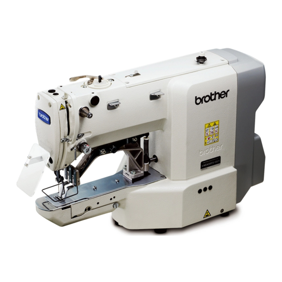
- Page 1 KE-430HX SERVICE MANUAL SERVICE MANUAL KE-430HS BE-438HX BE-438HS Please read this manual before making any adjustments. ELECTRONIC DIRECT DRIVE LOCKSTITCH BAR TACKER ELECTRONIC DIRECT DRIVE LOCKSTITCH BUTTON SEWER...
- Page 2 This service manual is intended for KE-430HX/KE-430HS and BE-438HX/BE-438HS; be sure to read the KE-430HX/ KE-438HS and BE-438HX/BE-438HS instruction manual before this manual. Carefully read the “SAFETY INSTRUCTIONS” below and the whole of this manual to understand this product before you start maintenance.
- Page 3 This symbol ( ) indicates something that you must do. The picture inside the circle indicates the ・・・・・・ nature of the thing that must be done. (For example, the symbol at left means “you must make the ground connection”.) KE-430HX/KE-430HS, BE-438HX/BE-438HS...
- Page 4 Contact your Brother dealer or a qualified electrician for any electrical work that may need to Secure the table so that it will not move when tilting be done.
- Page 5 If the machine develops a problem, contact your to carry out threading. nearest Brother dealer or a qualified technician. If using a work table which has casters, the casters should be secured in such a way so that they cannot move.
- Page 6 If only one hand is used, the weight of the machine Ask your Brother dealer or a qualified electrician to head may cause your hand to slip, and your hand carry out any maintenance and inspection of the may get caught.
- Page 7 Please follow the instructions on the labels at all times when using the machine. If the labels have been removed or are difficult to read, please contact your nearest Brother dealer. Touching areas where high voltages are present will result in severe injury.
- Page 8 2559B 3854B Thread take-up cover 3856B KE-430HX only Eye guard Finger guard Transformer box (100V/110V/380V/400V) Oil tank Rear cover DT solenoid cover Side cover 4010B KE-430HX/KE-430HS, BE-438HX/BE-438HS...
-
Page 9: Table Of Contents
5-1-5. Adding sections ..........44 6-8. Thread nipper mechanism 5-1-6. Changing tension codes within a section ..45 (KE-430HX -03, -0K, -01 specifications only) ..86 5-1-7. Deleting sections ........... 46 7. DISASSEMBLY ........5-2. X and Y parallel movement of sewing patterns ..47 5-3. - Page 10 Thread trimmer mechanism (1) ......109 9-19. Adjusting the X- and Y-feed motor home 8-6. Thread nipper mechanism position ............148 (KE-430HX-03, -0K, -01 specifications only) ..110 9-20. Adjusting the work clamp motor home 8-7. Work clamp lifter mechanism ......111 position ............150 8-8.
- Page 11 .......... 179 13-13. Button breakage (BE-438HX/HS) ....180 13-14. Work clamp height is unsuitable (KE-430HX/HS) ..........180 13-15. Button clamp height is unsuitable (BE-438HX/HS) ..........180 13-16. Thread wiper does not operate correctly ..180 13-17.
-
Page 12: Specifications
Machine head: approx. 60 kg, Operation panel: approx. 0.4 kg Weights Control box: approx. 7 kg 100V, 110V, 200V - 230V, 380V - 400V Power source * The voltages which can be used and the available regions may vary depending on the specifications. Power consumption 450 VA KE-430HX/KE-430HS, BE-438HX/BE-438HS... - Page 13 *5 The number of sewing patterns and the number of stitches that can be recorded will vary depending on the number of stitches in each sewing pattern. *6 If using a shank button, use the shank device (other than for Europe: SB7900-001, for Europe: SB7900-0E1). KE-430HX/KE-430HS, BE-438HX/BE-438HS...
-
Page 14: Notes On Handling
* While supporting the arm with both hands, gently lower it. 3915B Returning the machine head to the upright position 1. Pack away any tools which are near the table. 2. While supporting the arm with both hands, gently return the machine head to its original position. 3916B KE-430HX/KE-430HS, BE-438HX/BE-438HS... -
Page 15: Relationship Between Programs And Patterns
*1 Depending on the memory switch settings, the height of the work clamp/button clamp can also be set by means of parameters. *2 The PS300B can be used to create patterns and load them into actual sewing machines. KE-430HX/KE-430HS, BE-438HX/BE-438HS... - Page 16 PS300B can also be selected. * Patterns S001 to S089 (S001 to S064 for the 438HX/HS) are listed in “2-2. List of sewing patterns (KE-430HX/HS)” and “2-3. List of sewing patterns (BE-438HX/HS)” in the instruction manual. 4051B...
- Page 17 When memory switch No. 470 is set to ON. Work clamp/button clamp height (medium) (mm) 430H: 1 - 17 / 438H: 1 - 13 When memory switch No. 470 is set to ON. Upper thread tension setting value 0 - 300 KE-430HX/KE-430HS, BE-438HX/BE-438HS...
-
Page 18: Function Settings
・“9-21. Adjusting the thread nipper motor position” ・“9-22. Setting method for standard depression strokes (Foot switch)” ・“9-23. Data initialization method” ・“9-24. Adjusting the touch panel key position” ・“9-25. Correcting the digital tension output (KE-430HX, BE-438HX) ” ・“4-10. Updating the software version" KE-430HX/KE-430HS, BE-438HX/BE-438HS... - Page 19 4. FUNCTION SETTINGS Turn on power. If the power is turned on without any operations KE-430HX/KE-430HS, BE-438HX/BE-438HS...
-
Page 20: Memory Switch Setting Method (For Technicians)
(the value being displayed) is different from the initial value. When checking detailed explanations of memory switches You can touch the check key (7) to check the detailed explanation of the memory switch which is currently selected. KE-430HX/KE-430HS, BE-438HX/BE-438HS... - Page 21 OK key, you can cancel the changes. <Exiting the memory switch setting screen> ・At the special menu screen, press the home key to close the special menu and switch to the home screen. KE-430HX/KE-430HS, BE-438HX/BE-438HS...
-
Page 22: List Of Memory Switches (For Technicians)
(Start switch) Start 4: (Work clamp switch 1st step) Maximum drop → (Work clamp switch 2nd step) Start 5: (Work clamp switch 1st step) Drop to intermediate height → (Work clamp switch 2nd step) Maximum drop and start KE-430HX/KE-430HS, BE-438HX/BE-438HS... - Page 23 Depress Neutral 1st step 2nd step Depressed further Release Work clamp Sewing machine Work clamp raised maximum drop start Work clamp maximum drop Work clamp drop to Work clamp raised + Sewing machine intermediate height start 2984B 2985B KE-430HX/KE-430HS, BE-438HX/BE-438HS...
- Page 24 Work clamp Work clamp drop to maximum drop Work clamp raised intermediate + Sewing height machine start *1: Enabled when the work clamp switch is at neutral and the work clamp/button clamp is fully lowered. 2986B 2987B KE-430HX/KE-430HS, BE-438HX/BE-438HS...
- Page 25 430H: 400 − 3300 (sti/min) Sewing speed for 2nd stitch before the sewing end 438H: 400 − 2800 (sti/min) *1: The initial value will vary depending on the specifications. (Refer to “Initial values for each specification” on the following page.) KE-430HX/KE-430HS, BE-438HX/BE-438HS...
- Page 26 4. FUNCTION SETTINGS Initial values for each specification KE-430HX -03 KE-430HX -05 BE-438HX KE-430HX -01 KE-430HX -0K KE-430HS -03 KE-430HS -05 BE-438HS 1500 1200 1200 2000 2500 2500 2500 1200 3300 3300 3300 2500 3300 3300 3300 3300 2800 3300...
- Page 27 +: Feed timing becomes later. (degrees) 430H: -80 − 80 Changes the feed timing for the 2nd stitch at the sewing start (degrees) −: Feed timing becomes earlier. 438H: -100 − 100 +: Feed timing becomes later. (degrees) KE-430HX/KE-430HS, BE-438HX/BE-438HS...
- Page 28 −: Feed timing becomes earlier. +: Feed timing becomes later. (degrees) *1: This is not initialized during initialization mode. *2: The initial value will vary depending on the specifications. (Refer to “Initial values for each specification” on the following page.) KE-430HX/KE-430HS, BE-438HX/BE-438HS...
- Page 29 4. FUNCTION SETTINGS Initial values for each specification KE-430HX -03 KE-430HX -05 BE-438HX KE-430HX -01 KE-430HX -0K KE-430HS -03 KE-430HS -05 BE-438HS Initial Setting range Setting units Setting details value If the overall feed timing (setting No. 260) has been changed from the initial value, this specifies the effective number of stitches.
- Page 30 -5.0 − 5.0 Final stitch offset in Y direction (mm) 430H: 40.0 0.0 − 40.0 Sewing area limit in X direction (mm) * Setting range is 0.0 to 50.0 (mm) when No.473 is set to “1”. 438H: 6.4 KE-430HX/KE-430HS, BE-438HX/BE-438HS...
- Page 31 * Enabled when No. 470 is set to “OFF”. (mm) 430H: 1 − 17 (mm) Work clamp/button clamp intermediate drop position setting 438H: 1 − 13 * Enabled when No. 470 is set to “OFF”. (mm) Sewing area (430H only) 430H: 0 0: 40×30mm 1: 50×40mm KE-430HX/KE-430HS, BE-438HX/BE-438HS...
- Page 32 Nip timing offset for thread nipper device (degrees) -160 − 110 -110 Release timing offset for thread nipper device (degrees) *1: This is not displayed for models with digital tension. *2: This is not initialized during initialization mode. KE-430HX/KE-430HS, BE-438HX/BE-438HS...
- Page 33 ON: Enabled OFF: Disabled Time from error occurring to buzzer stopping OFF, 2 − 30 OFF: Buzzer does not stop. (seconds) 2 − 30: Buzzer stops after the specified time. *1: This is not initialized during initialization mode. KE-430HX/KE-430HS, BE-438HX/BE-438HS...
- Page 34 Eyelet bar tack closing device (old 432 series) OFF: Disabled OFF, 1 − 2 1: Eyelet bar tack closing device operates after the work clamp has dropped. 2: Eyelet bar tack closing device operates at the sewing start. KE-430HX/KE-430HS, BE-438HX/BE-438HS...
-
Page 35: Checking Input
Press the back key (5) to return to the special menu screen. <To exit from the special menu> ・ At the special menu screen, press the home key to close the special menu and switch to the home screen. KE-430HX/KE-430HS, BE-438HX/BE-438HS... - Page 36 Bobbin winding: 4 Threading: 5 Test: 6 Needle movement change IN-08 Key input 1 − 16 ▲: 7 F1: 8 F2: 9 F3: 10 Menu: 11 Needle movement change ▼: 12 F4: 13 F5: 14 F6: 15 Stop: 16 KE-430HX/KE-430HS, BE-438HX/BE-438HS...
- Page 37 ON when detected, External input 1 ON / OFF OFF when not detected ON when detected, IN-13 External input 2 ON / OFF OFF when not detected ON when detected, External input 3 ON / OFF OFF when not detected KE-430HX/KE-430HS, BE-438HX/BE-438HS...
-
Page 38: Checking Output
Press the back key (6) to return to the special menu screen. <To exit from the special menu> ・ At the special menu screen, press the home key to close the special menu and switch to the home screen. KE-430HX/KE-430HS, BE-438HX/BE-438HS... - Page 39 OFF while it is released OUT-09 External output 1: External output 1 2: External output 2 3: External output 3 ON when OK key is pressed, and OFF automatically after the specified OUT-10 Optional solenoid time has elapsed KE-430HX/KE-430HS, BE-438HX/BE-438HS...
-
Page 40: Checking The Software Version
<Exiting software version checking mode> ・Press the back key to return to the special menu screen. <Exiting the special menu> ・At the special menu screen, press the home key to close the special menu and switch to the home screen. KE-430HX/KE-430HS, BE-438HX/BE-438HS... -
Page 41: Maintenance Information List
Press the back key (6) to return to the special menu screen. <To exit from the special menu> ・ At the special menu screen, press the home key to close the special menu and switch to the home screen. KE-430HX/KE-430HS, BE-438HX/BE-438HS... - Page 42 The total number of stitches sewn since the lubricating oil was replaced and the actual display value can be cleared. * The oil counter value can be cleared by touching the RESET key and then touching the OK key KE-430HX/KE-430HS, BE-438HX/BE-438HS...
-
Page 43: Checking The Error History
1. If you press an error item, the display will switch to the error handling screen for the selected item. 2. The remedy for the error code is displayed. Press the back key to return to the error history screen. KE-430HX/KE-430HS, BE-438HX/BE-438HS... - Page 44 (3) without pressing the OK key, the error history will not be cleared. <To exit from the special menu> ・ At the special menu screen, press the home key to close the special menu and switch to the home screen. KE-430HX/KE-430HS, BE-438HX/BE-438HS...
-
Page 45: Making Protection Settings
3. Touch an item, and then select whether to enable or disable protection for that item. :Protection setting is enabled (changing settings is disallowed) :Protection setting is disabled (changing settings is allowed) 4. Press the OK key to confirm the protection setting. KE-430HX/KE-430HS, BE-438HX/BE-438HS... - Page 46 1. At the Individual selection of protection setting screen, select the ALL key (3). 2. All items will have a check mark alongside them. * You can clear all of the check marks by pressing the ALL key again. 3. Press the OK key to confirm the setting. KE-430HX/KE-430HS, BE-438HX/BE-438HS...
- Page 47 Program copy operations in the setting menu are disallowed. Data reading and writing operations in the setting menu and maintenance data Read/Write data writing operations in the special menu are disallowed. Restart sewing Restarting sewing from an interrupted position is disallowed. KE-430HX/KE-430HS, BE-438HX/BE-438HS...
-
Page 48: Updating The Software Version
<While version updates are running> 1. While version updating is in progress, the progress status will be displayed. * Do not turn off the power while version updating is in progress. 2. Once version updating is finished, turn off the power. KE-430HX/KE-430HS, BE-438HX/BE-438HS... - Page 49 <While version updates are running> 1. While version updating is in progress, the progress status will be displayed. * Do not turn off the power while version updating is in progress. 2. Once version updating is finished, turn off the power. KE-430HX/KE-430HS, BE-438HX/BE-438HS...
- Page 50 <While version updates are running> 1. While version updating is in progress, the progress status will be displayed. * Do not turn off the power while version updating is in progress. 2. Once version updating is finished, turn off the power. KE-430HX/KE-430HS, BE-438HX/BE-438HS...
-
Page 51: Setting Function
Needle Drop No. Section No. Tension value 1st stitch 2nd stitch (to 9th stitch) 10th stitch (to 27th stitch) 28th stitch (to final stitch) Tension code diagram Vertical axis: Tension value Section Horizontal axis: Number of stitches Final stitch KE-430HX/KE-430HS, BE-438HX/BE-438HS... -
Page 52: Work Flowchart
Add a tension code at the point to be changed. Refer to "5-1-3. Checking pattern data" and "5-1-6. Changing tension codes within a section". Deleted? Select the section to be deleted and then delete it. Refer to "5-1-3. Checking pattern data" and "5-1-7. Deleting sections". KE-430HX/KE-430HS, BE-438HX/BE-438HS... -
Page 53: Switching To Pattern Editing Mode
Depress the foot switch to the 2nd step. 2nd step ・ Home position is detected, and then the sewing machine moves to the sewing start position. From this point on, the condition is referred to as pattern editing mode. 4441Q KE-430HX/KE-430HS, BE-438HX/BE-438HS... -
Page 54: Checking Pattern Data
For details on the program copying method, refer to "5-16. Copying programs (additional programs)". You can use the initialization or additional program deletion functions to delete any sewing program data which has been added to that program by copying. Refer to "9-23. Data initialization method" and "5-7. Deleting additional programs". KE-430HX/KE-430HS, BE-438HX/BE-438HS... -
Page 55: Adding Sections
If you would like to end pattern editing without adding any sections, press the back key , the menu key or the home key KE-430HX/KE-430HS, BE-438HX/BE-438HS... -
Page 56: Changing Tension Codes Within A Section
If you press the needle movement change key [ ] or ] before pressing the key, the tension change will be canceled. If you would like to end pattern editing without changing any sections, press the back key , the menu key or the home key KE-430HX/KE-430HS, BE-438HX/BE-438HS... -
Page 57: Deleting Sections
1 at the beginning of the program alone cannot be deleted. If you would like to end pattern editing without deleting any sections, making any changes, press the back key , the menu key or the home key KE-430HX/KE-430HS, BE-438HX/BE-438HS... -
Page 58: And Y Parallel Movement Of Sewing Patterns
If the sewing pattern goes outside the sewing area as a result of parallel movement, sewing will not be possible. For example, set to 3.00. KE-430HX/KE-430HS, BE-438HX/BE-438HS... - Page 59 When the power switch is turned off, the movement amount which has been stored will be reset. However, if memory switch No. 465 is set to “2”, the movement amount will remain stored and will not be reset. KE-430HX/KE-430HS, BE-438HX/BE-438HS...
-
Page 60: Memory Switch Setting Method (For Operators)
・ You can make the initial setting appear in the display by touching the reset key (5). When checking detailed explanations of memory switches You can touch the check key (6) to check the detailed explanation of the memory switch which is currently selected. KE-430HX/KE-430HS, BE-438HX/BE-438HS... - Page 61 Assignment to F1 key: memory switch No. 407 Assignment to F2 key: memory switch No. 408 Assignment to F3 key: memory switch No. 409 Assignment to F4 key: memory switch No. 410 KE-430HX/KE-430HS, BE-438HX/BE-438HS...
- Page 62 Thread nipper device can be used. (*1) *1 The setting is enabled when memory switch No. 100 is set to "ON", the slow start pattern is set to 8 or 9 and when the sewing speed value is set to 1,500 sti/min or more. KE-430HX/KE-430HS, BE-438HX/BE-438HS...
-
Page 63: Slow Start Pattern Setting Method
Sewing speed for the 3rd stitch 1,500 Sewing speed for the 4th stitch 2,000 2,000 The speed will not be faster than the sewing speed which has been set. The thread nipper device will not operate for settings other than 8 and 9. KE-430HX/KE-430HS, BE-438HX/BE-438HS... -
Page 64: Illumination Led Brightness Setting Method
For details on loading additional programs from USB memory, refer to "5-18-5. Reading additional pattern data". For details on the program copying method, refer to "5-16. Copying programs (additional programs)". For details on editing tension codes, refer to "5-1. Editing patterns". KE-430HX/KE-430HS, BE-438HX/BE-438HS... -
Page 65: Deleting Additional Programs
・ At the delete additional program screen, you can press the back key or the menu key to return to the setting menu. ・ In addition, when the home key is pressed, the display switches to the home screen. KE-430HX/KE-430HS, BE-438HX/BE-438HS... -
Page 66: User Program Setting Method
(1) to switch to the select program screen, and select the program. ・ The setting ranges for other items will vary in accordance with the pattern which is registered, so register the pattern first. KE-430HX/KE-430HS, BE-438HX/BE-438HS... - Page 67 ・ If you press the back key without pressing the OK key, you can return to the select user program screen and cancel the changes to parameter settings. If you would like to continue another program, repeat steps 2 to 8 above. KE-430HX/KE-430HS, BE-438HX/BE-438HS...
- Page 68 No. 402 to "ON". 430HX/HS: 200 sti/min to 3,300 sti/min 430HX/HS: 200 sti/min to 2,800 sti/min The setting is in units of 100 sti/min. Sewing (Initial value: 2,700 sti/min for the 430HX/HS speed 2,300 sti/min for the 438HX/HS) Initial value KE-430HX/KE-430HS, BE-438HX/BE-438HS...
- Page 69 (Initial value is 10.) * It is possible to change the value of intermediate work clamp height (L) only when memory switch No. 071 is set to "2" or memory switch No. 072 is set to "2" or "5". KE-430HX/KE-430HS, BE-438HX/BE-438HS...
-
Page 70: Deleting User Programs
・ At the delete user program screen, you can press the back key or the menu key to return to the setting menu. ・ In addition, when the home key is pressed, the display switches to the home screen. KE-430HX/KE-430HS, BE-438HX/BE-438HS... -
Page 71: Cycle Program Setting
Once a step has been selected and a check mark appears, touch the step select key (4). ・ The display will switch to the select user program screen. ・ The user programs which have been registered will be set in the selected step. KE-430HX/KE-430HS, BE-438HX/BE-438HS... - Page 72 ・ At the delete user program screen, you can press the back key or the menu key to return to the setting menu. ・ In addition, when the home key is pressed, the display switches to the home screen. KE-430HX/KE-430HS, BE-438HX/BE-438HS...
-
Page 73: Deleting Cycle Programs
・ At the delete cycle program screen, you can press the back key or the menu key to return to the setting menu. ・ In addition, when the home key is pressed, the display switches to the home screen. KE-430HX/KE-430HS, BE-438HX/BE-438HS... -
Page 74: Using The Lower Thread Counter
3. If you touch the reset key (2), the display will switch to the home screen, the lower thread counter value will return to the setting value, and sewing will be possible. KE-430HX/KE-430HS, BE-438HX/BE-438HS... -
Page 75: Using The Production Counter
・ The counter value displayed in the home screen is incremented by 1 each time one sewing operation is completed. * The lower 5 digits are displayed in the home screen. If you would like all digits to be displayed, check using the production counter setting screen. KE-430HX/KE-430HS, BE-438HX/BE-438HS... -
Page 76: Using The Garment Counter
・ The garment counter will not be displayed on the home screen when sewing programs other than cycle programs. ・ The counter value which is displayed on the home screen will be incremented by 1 each time all of the steps in the selected cycle program have been sewn once. KE-430HX/KE-430HS, BE-438HX/BE-438HS... -
Page 77: Split Setting
・ON=Single split mode Only the split section which is selected in the split settings can be sewn. ・OFF=Continuous split mode Sewing can be carried out from the split section which is selected in the split settings to the sewing end. KE-430HX/KE-430HS, BE-438HX/BE-438HS... -
Page 78: Copying Programs (Additional Program)
Change the necessary items. Carry out the steps in "5-4. Setting the X scale and Y scale", "5-5. Setting the sewing speed" and "5-6. Setting the work clamp height" in the instruction manual, and change the necessary items. KE-430HX/KE-430HS, BE-438HX/BE-438HS... -
Page 79: Uniform Tension Correction
(2) in the tension value display. Confirm the correction value. Touch the OK key ・ The correction value will be confirmed, and it will be applied to the upper thread tension value the next time sewing is carried out. KE-430HX/KE-430HS, BE-438HX/BE-438HS... -
Page 80: Using Usb Memory
Sewing parameters of Same as above ISMUPG.SEW programs Cycle program Same as above ISMCYC.SEW Stores the files which relate to error logs. Error log Same as above (The data can only be written from the maintenance information screen.) KE-430HX/KE-430HS, BE-438HX/BE-438HS... -
Page 81: Preparation For Reading/Writing Data
Same as for "Export all data" in the "Read/Write data" list. Export maintenance Memory switch settings and error logs are written to the USB memory. information The additional sewing data that can be used with this sewing machine is data that has been created for KE-430H/BE-438H models. KE-430HX/KE-430HS, BE-438HX/BE-438HS... -
Page 82: Reading All Data
・ At the Read/Write data screen, you can press the back key or the menu key to return to the setting menu. ・ In addition, when the home key is pressed, the display switches to the home screen. KE-430HX/KE-430HS, BE-438HX/BE-438HS... -
Page 83: Writing All Data To Usb Memory
・ At the Read/Write data screen, you can press the back key or the menu key to return to the setting menu. ・ In addition, when the home key is pressed, the display switches to the home screen. KE-430HX/KE-430HS, BE-438HX/BE-438HS... - Page 84 You can return to the special menu by pressing the back key <To exit from the special menu> ・ At the special menu screen, press the home key to close the special menu and switch to the home screen. KE-430HX/KE-430HS, BE-438HX/BE-438HS...
-
Page 85: Reading Additional Pattern Data
・ At the Read/Write data screen, you can press the back key or the menu key to return to the setting menu. ・ In addition, when the home key is pressed, the display switches to the home screen. KE-430HX/KE-430HS, BE-438HX/BE-438HS... -
Page 86: Writing Additional Pattern Data To An Usb Memory
・ At the Read/Write data screen, you can press the back key or the menu key to return to the setting menu. ・ In addition, when the home key is pressed, the display switches to the home screen. KE-430HX/KE-430HS, BE-438HX/BE-438HS... -
Page 87: Reading Program Data
・ At the Read/Write data screen, you can press the back key or the menu key to return to the setting menu. ・ In addition, when the home key is pressed, the display switches to the home screen. KE-430HX/KE-430HS, BE-438HX/BE-438HS... -
Page 88: Writing Program Data To An Usb Memory
・ At the Read/Write data screen, you can press the back key or the menu key to return to the setting menu. ・ In addition, when the home key is pressed, the display switches to the home screen. KE-430HX/KE-430HS, BE-438HX/BE-438HS... -
Page 89: Reading Memory Switch Data
・ At the Read/Write data screen, you can press the back key or the menu key to return to the setting menu. ・ In addition, when the home key is pressed, the display switches to the home screen. KE-430HX/KE-430HS, BE-438HX/BE-438HS... -
Page 90: Usb Memory
・ At the Read/Write data screen, you can press the back key or the menu key to return to the setting menu. ・ In addition, when the home key is pressed, the display switches to the home screen. KE-430HX/KE-430HS, BE-438HX/BE-438HS... -
Page 91: Writing Error Log Data And Memory Switch Data To Usb Memory
You can return to the special menu by pressing the back key <To exit from the special menu> ・ At the special menu screen, press the home key to close the special menu and switch to the home screen. KE-430HX/KE-430HS, BE-438HX/BE-438HS... -
Page 92: Mechanical Descriptions
1. Pulley 2. Upper shaft 3. Crank rod assembly 4. Rock gear shaft F assembly 5. Rock gear shaft R assembly 6. Rock gear 7. Lower gear <7> Splash plate 8. Lower shaft assembly 9. Driver 10. Shuttle hook KE-430HX/KE-430HS, BE-438HX/BE-438HS... -
Page 93: Work Clamp Lifter Mechanism
8. Button clamp rod 9. Button clamp lever 10. Button clamp holder hook assembly 11. Button clamp holder shaft * When the work clamp pulse motor is turned off, the button 12. Button clamp clamp rod rises, and button clamps lower. KE-430HX/KE-430HS, BE-438HX/BE-438HS... -
Page 94: Thread Wiper Mechanism
1. Pulse motor P assembly 2. Gear 16 3. Cam gear 4. Cam shaft 5. Thread wiper cam 6. Thread wiper roller 7. Thread wiper driving lever 8. Thread wiper rod assembly 9. Connecting plate 10. Thread wiper arm assembly KE-430HX/KE-430HS, BE-438HX/BE-438HS... -
Page 95: Feed Mechanism
4. X-feed lever 5. Regulator block assembly 3975B 6. Feed bar sub assembly Y direction 1. Pulse motor Y assembly 2. Feed gear 3. Y-feed rack shaft 4. Y-feed rack shaft clamp 5. Feed bar sub assembly 3976B KE-430HX/KE-430HS, BE-438HX/BE-438HS... -
Page 96: Thread Trimmer Mechanism
2. Thread trimmer cam 3. Thread trimmer collar H 4. Thread trimmer cam lever 5. Thread trimmer lever 6. Thread trimmer link 7. Thread trimmer rod 8. Movable knife lever 9. Movable knife connecting plate 10. Movable knife KE-430HX/KE-430HS, BE-438HX/BE-438HS... -
Page 97: Tension Release Mechanism
1. Tension release solenoid 2. Bolt 3. Tension release bar 4. Tension release pin 3776B 6-8. Thread nipper mechanism (KE-430HX -03, -0K, -01 specifications only) 1. Pulse motor Y assembly 2. Thread trimmer cam 3. Thread trimmer collar H 4. TN-driving lever 5. -
Page 98: Disassembly
Turn off the power switch before carrying out Brother will not be held responsible for any accidents disassembly, otherwise the machine may operate if or problems resulting from the use of non-genuine the foot switch is depressed by mistake, which may parts. -
Page 99: Covers
12. Face plate 5. Screws [4 pcs] 13. Face plate packing 6. Side cover 14. Shoulder screws 8-2 [2 pcs] 7. Bolts [2 pcs] 15. Washers, wave spring [2 pcs] 8. Eye guard assembly 16. Shuttle race cover assembly KE-430HX/KE-430HS, BE-438HX/BE-438HS... -
Page 100: Work Clamp Arm Mechanism
BE-438HX/BE-438HS 3983B 2. Set screws [2 pcs: Loosen] 1. Tension nuts [2 pcs] 3. Button clamp holder shaft Adjusting nut 4. Button clamp holder Compression spring [Push upward and remove horizontally] 5. Screws [2 pcs] 6. Feed plate KE-430HX/KE-430HS, BE-438HX/BE-438HS... -
Page 101: Needle Bar Mechanism
16. Set screws [2 pcs: Loosen] 27. Bolts [2 pcs] 9. Needle bar thread guide 17. Set screws [2 pcs: Loosen] 28. Slide block guide 18. Thread take-up spring shaft assembly 19. Set screw collar (Continued on next page.) KE-430HX/KE-430HS, BE-438HX/BE-438HS... - Page 102 15. Set screws [2 pcs: Loosen] 23. Thread take-up lever assembly 7. Wick holder assembly 16. Thread take-up spring shaft assembly 24. Washer 8. Rubber cap 17. Set screw collar 25. Bolts [2 pcs] 9. Screw 18. Screw [Loosen] 26. Slide block guide KE-430HX/KE-430HS, BE-438HX/BE-438HS...
-
Page 103: Thread Trimmer Mechanism
14. Thread trimmer cam lever shaft 15. Washers [2 pcs] 16. Thread trimmer cam For the KE-430HX/HS (-05 specifications) and BE-438HX/HS, parts marked 17. Socket bolt (S/P washer) with * are supplied as accessories. Install them if necessary. 18. Thread trimmer lever... -
Page 104: Thread Nipper Mechanism
7. DISASSEMBLY 7-5. Thread nipper mechanism (KE-430HX-03, -0K, -01 specifications only) 4002B 1. Thread nipper driving lever spring 7. Thread nipper connecting plate R 13. Shoulder screw 6-0.9 2. Link shoulder screw 8. Thread nipper connecting plate F assembly 14. Thread nipper U 3. -
Page 105: Upper Shaft Mechanism
(1) Oil (2) Tool (3) Pulse motor X assembly 1. Screws [10 pcs] 2. Bed bottom cover assembly 3. Screws [2 pcs] 4. Lower shaft felt assembly 5. Bolt 6. Crank rod washer 4007B (Continued on next page.) KE-430HX/KE-430HS, BE-438HX/BE-438HS... - Page 106 31. Upper shaft [Tap out toward the rear] 17. Crank lubrication assembly 32. Ball bearing bush M assembly 18. Screw 33. Oil seal 19. Set screw [Loosen] 34. Pulley gear R 20. Screws [2 pcs] 35. Thread take-up crank assembly 21. Plain washers [2 pcs] KE-430HX/KE-430HS, BE-438HX/BE-438HS...
-
Page 107: Lower Shaft Mechanism
6. Oil tube support 7. Screw 8. Cord holder U3 9. Shuttle race base assembly 3989B 10. Socket bolts (S/P washer) [2 pcs] 11. Splash plate 12. Rubber caps [2 pcs] 13. Set screws [4 pcs: Loosen] (Continued on next page.) KE-430HX/KE-430HS, BE-438HX/BE-438HS... - Page 108 17. Oil seal and the bearing bush together toward the rear.] 18. Rock gear shaft F assembly [Pull forward] 24. Bearing bush assembly 19. Rock gear 25. Bearing bush assembly 20. Set screws [6 pcs: Loosen] 26. Oil seal KE-430HX/KE-430HS, BE-438HX/BE-438HS...
-
Page 109: Feed Mechanism
14. Y-feed rack shaft 15. Screws [2 pcs] 16. X-feed gear cover 17. Bolt [Loosen] 18. X-feed gear 19. Socket bolts (S/P washer) [3 pcs] 3993B 20. X-motor setting plate [Pulse motor X assembly] 21. X-feed lever [Pull upward] 3994B KE-430HX/KE-430HS, BE-438HX/BE-438HS... -
Page 110: Lubrication
3. Screws [2 pcs] 8. O rings [2 pcs] 13. Wiper shaft 4. Plain washers [2 pcs] 9. Connecting plate [Pull upward] 14. Thread wiper rod assembly 5. Thread wiper arm assembly 10. Set screw [Loosen] [Pull forward] KE-430HX/KE-430HS, BE-438HX/BE-438HS... -
Page 111: Work Clamp Lifter Mechanism
21. Work clamp cam shaft 6. Set screws [2 pcs: Loosen] 14. Work clamp driving lever 22. Cam gear 7. Gear 16 15. Plain washer 23. Thread wiper cam 8. Springs [2 pcs] 16. Thread wiper driving lever (Continued on next page.) KE-430HX/KE-430HS, BE-438HX/BE-438HS... - Page 112 37. Button clamp rod [Pull upward] 38. Set screw [Loosen] 39. Button clamp lever shaft [Pull out] 40. Retaining ring E 41. Plain washer 42. Button clamp lever 43. Bolts [2 pcs] 44. Button clamp lever holder 3998B KE-430HX/KE-430HS, BE-438HX/BE-438HS...
-
Page 113: Threading Mechanism
7. DISASSEMBLY 7-12. Threading mechanism KE-430HX, BE-438HX 1. Set screw [Loosen] 2. Tension bracket [Pull out] 3. Tension release pin 4. Nut 5. Plain washer 6. Set screw [Loosen] 7. Tension stud assembly [Pull out] 8. Thread take-up spring 3999B... -
Page 114: Tension Release Mechanism
2. Solenoid cover 8. Solenoid setting plate 3. Screws [2 pcs] 9. Bolt 4001B 4. Tension solenoid 10. Nut (KE-430HX, BE-438HX) 11. Plain washer 12. Solenoid cushion Tension release solenoid (KE-430HS, BE-438HS) 13. Tension release bar 5. Bolts [2 pcs] 14. -
Page 115: Led Mechanism
7. DISASSEMBLY 7-15. LED mechanism 1. Bolt 2. LED setting plate 3. LED assembly 4011B KE-430HX/KE-430HS, BE-438HX/BE-438HS... -
Page 116: Assembly
* (number) indicates part names only. (The numbers do not indicate the order of assembly.) * Apply grease to the required places when reassembling the parts and once every two years. Unless otherwise specified, use Brother-specified "Grease unit (other than for Europe: SA8771-101, for Europe: SB6659-101)". -
Page 117: Tension Release Mechanism
“9-14. Adjusting the tension release amount (KE-430HX, BE-438HX)”. 1. Tension release bar 2. Tension release spring(KE-430HX, BE-438HS) 3. Tension solenoid (KE-430HX, BE-438HX) Tension release solenoid (KE-430HS, BE-438HS) 4013B 4. Solenoid setting plate 5. Plain washers [2 pcs] 6. Spring washers [2 pcs] 7. -
Page 118: Threading Mechanism
8. ASSEMBLY 8-3. Threading mechanism KE-430HX, BE-438HX While gently pushing the tension stud assembly 3 in the direction shown in the illustration, tighten the set screw 6 until there is no clearance between the tension bracket 1 and the nut 5. -
Page 119: Thread Wiper Mechanism
7. Connecting plate 12. Screws [2 pcs] 3. Plain washer 8. Plain washer 13. Retaining ring E 4. Retaining ring E 9. Retaining ring E 14. Set screw [Tighten] 5. Set screw [Tighten] 10. Thread wiper arm assembly KE-430HX/KE-430HS, BE-438HX/BE-438HS... -
Page 120: Thread Trimmer Mechanism (1)
28. Bolts [2 pcs] 9. Thread trimmer lever 19. Set screws [2 pcs] 10. Socket bolt (S/P washer) 20. Set screws [2 pcs] For the KE-430HX-03, -0K, -01, install the parts marked with * as the thread nipper parts. KE-430HX/KE-430HS, BE-438HX/BE-438HS... -
Page 121: Thread Nipper Mechanism (Ke-430Hx-03, -0K, -01 Specifications Only)
8. ASSEMBLY 8-6. Thread nipper mechanism (KE-430HX-03, -0K, -01 specifications only) Apply grease to the portions indicated by the white arrows. The TN-driving lever 14 and the washer 15 which are Adjust while referring to “9-21. Adjusting the marked with * should be installed at the time of thread nipper motor position”. -
Page 122: Work Clamp Lifter Mechanism
21. Bolts [3 pcs] 6. W-clamp cam shaft 14. Retaining ring E 22. Link shoulder screw 7. Set screws [4 pcs: Tighten] 15. Set screws [2 pcs: Tighten] 16. Gear 16 8. Set screw collar (Continued on next page.) KE-430HX/KE-430HS, BE-438HX/BE-438HS... - Page 123 Make sure that the harness connector is facing the correct way at this time. Engage drive gear 16 16 and the cam gear 4, and while taking up the backlash (play), install the pulse motor P assembly 17. (Continued on next page.) KE-430HX/KE-430HS, BE-438HX/BE-438HS...
- Page 124 (438H) is lowered, the needle bar guide slide block 24 (430H) or 35 (438H) moves away, so hold the work clamp lifter plate assembly 23 (430H)/button clamp rod 30 (438H) in place until the link shoulder screw 4066B 31 (430H) or 42 (438H) is tightened. KE-430HX/KE-430HS, BE-438HX/BE-438HS...
-
Page 125: Feed Mechanism
Engage the feed gear 1 and the X-feed gear 6 so that the index marks are as close together as possible, and then tighten the bolt 7 so that the gears move smoothly in the axial direction with no play. (Continued on next page.) KE-430HX/KE-430HS, BE-438HX/BE-438HS... - Page 126 Move the feed bar sub assembly 15 back and forth so that the Y-feed rack shaft 10 and the feed bar sub assembly 15 move smoothly, and then tighten the two bolts 13 and two screws 14. (Continued on next page.) KE-430HX/KE-430HS, BE-438HX/BE-438HS...
- Page 127 * For the BE-438H, be particularly careful that the Approx. 100 mm mechanism is in the correct position shown in the illustration. 4029B After installing, adjust while referring to "9-19. Adjusting the X- and Y-feed motor home position" KE-430HX/KE-430HS, BE-438HX/BE-438HS...
-
Page 128: Lower Shaft Mechanism
Apply grease to the portions indicated by the white arrows. 1. Shuttle race base assembly 2. Oil tube support 3. Screw 4. Cord holder U3 5. Screw 6. Adjusting stud 7. Set screw [Tighten] GREASE BZL-302R GREASE BZL-302R 4033B (Continued on next page.) KE-430HX/KE-430HS, BE-438HX/BE-438HS... - Page 129 Gap distribution Gap distribution 4035B 8. Rock gear 9. Rock gear shaft F assembly 10. Oil seal 11. Rock gear shaft R assembly 12. Set screws [2 pcs: Tighten] 13. Set screws [2 pcs: Tighten] (Continued on next page.) KE-430HX/KE-430HS, BE-438HX/BE-438HS...
- Page 130 16. Bearing bush assembly 17. Lower shaft assembly 18. Oil seal 19. Bearing bush assembly 20. Set screws [6 pcs: Tighten] 21. Driver 22. Bolt [Temporarily tighten] 23. Set screws [4 pcs] 24. Rubber caps [2 pcs] (Temporarily tighten) 4037B KE-430HX/KE-430HS, BE-438HX/BE-438HS...
-
Page 131: Upper Shaft Mechanism
* Set screws marked with * in the illustration are on the screw stop side. Refer to the next page for the points to note during reassembly. A on next page 1. Crank lubrication assembly 2. Screws [2 pcs] 3. Tube holder 4. Screw 4030B (Continued on next page.) KE-430HX/KE-430HS, BE-438HX/BE-438HS... - Page 132 20. Bolts [2 pcs] 11. Set screw 29. Plain washers [2 pcs] 21. Washer crank rod 30. Screws [2 pcs] 12. Set screws [2 pcs] 22. Bolt 13. Set screws [2 pcs] 14. Oil seal (Continued on next page.) KE-430HX/KE-430HS, BE-438HX/BE-438HS...
- Page 133 9 and motor shaft and then tighten the screw Install pulley gear R 8 so that it is aligned with a in B again. the reference line on the upper shaft 9. (Continued on next page.) KE-430HX/KE-430HS, BE-438HX/BE-438HS...
- Page 134 37. Bed bottom cover 32. Splash plate 38. Screws [10 pcs] 33. Socket bolts (S/P washer) [2 pcs] 39. O ring 34. Lower shaft felt assembly 40. Screw 35. Screws [2 pcs] 41. Rubber caps [2 pcs] 36. Bottom cover packing KE-430HX/KE-430HS, BE-438HX/BE-438HS...
-
Page 135: Needle Bar Mechanism
8. ASSEMBLY 8-11. Needle bar mechanism Apply grease to the portions indicated by the white arrows. When tightening the two set screws 7, KE-430HX, BE-438HX first turn the pulley approximately 10 times to the position where it turns Inside hole smoothly. - Page 136 17. Needle bar [Insert from above] 22. Air nozzle assembly 26. Needle bar thread guide 18. Screw 23. Screws [2 pcs] 27. Needle 19. Air cylinder cap assembly 24. Cord holders [2 pcs] 28. Screw 20. Middle plate (Continued on next page.) KE-430HX/KE-430HS, BE-438HX/BE-438HS...
- Page 137 (top reference line) is aligned with the lower edge of the needle bar bush when the machine pulley is turned to lower the needle bar 17 to its lowest position, and then set the cut section so that it is facing forward and tighten the screw 18. 4647Q KE-430HX/KE-430HS, BE-438HX/BE-438HS...
-
Page 138: Lubrication
3. Shuttle race base setting claw [Close] 4. Bobbin case assembly After installing the shuttle hook 1, carry out the adjustments in “9-3. Adjusting the needle bar lift amount and the driver needle guard” and “9-4. Adjusting the needle clearance”. KE-430HX/KE-430HS, BE-438HX/BE-438HS... -
Page 139: Thread Trimmer Mechanism (2)
13. Needle plate KE-430HX/HS (-05 6. Movable knife collar 14. Flat screws [2 pcs] specifications) and BE-438HX/HS, parts 7. Thrust collar 15. Screws [2 pcs] marked with supplied 8. Movable knife shoulder screw accessories. Install them if necessary. KE-430HX/KE-430HS, BE-438HX/BE-438HS... -
Page 140: Work Clamp Arm Mechanism (Ke-430Hx/Hs)
8. ASSEMBLY 8-15. Work clamp arm mechanism (KE-430HX/HS) Push the work clamp arm lever plate (3) in the direction of the arrow to raise the work clamp (4) by about 5 mm, set so that there is a clearance of 0.1 mm between the... -
Page 141: Work Clamp Arm Mechanism (Be-438Hx/Hs)
After installing, check that the needle passes into the button hole without touching the button. (Refer to “9-12. Adjusting the position of the button clamp (BE-438HX/HS)”.) Apply grease to the portions indicated by the white arrows. It is recommended that you use commercially-available <JXTG Nippon Oil & Energy POWERNOC WB 2>. 4045B KE-430HX/KE-430HS, BE-438HX/BE-438HS... -
Page 142: Covers
3. Shoulder screws, 8-2 [2 pcs] 11. Side cover 4. Face plate packing 12. Screws [4 pcs] 5. Face plate 13. Rear cover 6. Screws [3 pcs] 14. Screws [4 pcs] 7. LED cover 15. Top cover 8. Screw 16. Screws [4 pcs] KE-430HX/KE-430HS, BE-438HX/BE-438HS... -
Page 143: Adjustment
If only one hand is used, the weight of the machine Ask your Brother dealer or a qualified electrician to head may cause your hand to slip, and your hand carry out any maintenance and inspection of the may get caught. -
Page 144: Upper And Lower Thread Tension
* If the work clamp/button clamp is lowered when the work clamp switch is released, the thread tension output will be maintained. * The above operations are enabled when memory switch No. 072 is set to “1” or “2”. KE-430HX/KE-430HS, BE-438HX/BE-438HS... -
Page 145: Thread Take-Up Spring
Higher Loosen the set screw (1) and turn the tensioner body to adjust the thread take-up spring height. 3896B <Thread take-up spring tension> < For the KE-430HX and BE-438HX > Stronger Weaker < For the KE-430HS and BE-438HS > Stronger... -
Page 146: Arm Thread Guide C
(5) and then move the needle bar up or down to adjust so that the second reference line from the bottom of the needle bar (reference line A) is aligned with the lower edge of the needle bar bush (3). * If using a DP x 5 needle, use the highest reference line (reference line a). KE-430HX/KE-430HS, BE-438HX/BE-438HS... -
Page 147: Adjusting The Needle Bar Lift Amount And The Driver Needle Guard
Turn the pulley in the direction of the arrow to align the tip of the shuttle hook with the needle center line. Then loosen the set screw (1) and turn the adjusting stud (2) to adjust so that the clearance between the needle and the tip of the shuttle hook is 0.01 to 0.08 mm. KE-430HX/KE-430HS, BE-438HX/BE-438HS... -
Page 148: Adjusting The Shuttle Race Thread Guide
The position of the shuttle race thread guide is adjusted at the time of shipment from the factory. It should not be changed if at all possible. 9-6. Hook lubrication amount KE-430HX/HS (-05 specifications) KE-430HX/HS (-03, -0K, -01 specifications), BE-438HX/HS More More Less... -
Page 149: Adjusting The Position Of The Movable Knife
(6) is touching the edge of the index mark (7), and then tighten the bolt (4) while keeping the parts in this position. 7. Install the motor bracket rear cover (1). 8. Return the machine head to its original position, and then install the rear cover. KE-430HX/KE-430HS, BE-438HX/BE-438HS... -
Page 150: Replacing The Movable Knife And Fixed Knife
* Move the movable knife (6) as shown in the illustration and check that it trims the thread cleanly. NOTE: If the movable knife spacer (11) is too thick, it will not be possible to trim the thread. 2334B KE-430HX/KE-430HS, BE-438HX/BE-438HS... -
Page 151: Adjusting The Work Clamp Lift Amount (Ke-430Hx/Hs)
9. ADJUSTMENT 9-9. Adjusting the work clamp lift amount (KE-430HX/HS) Adjust so that the actual maximum lift amount for the work clamp is 17 mm above the top of the needle plate when the maximum work clamp height has been set to 17 mm using the operation panel. -
Page 152: Adjusting The Holding Pressure (Be-438Hx/Hs)
9-12. Adjusting the position of the button clamp (BE-438HX/HS) 1. Loosen the two bolts (1) and adjust the button clamp base (2) by moving it. 2. Carry out test feeding to check that the needle will go through the button hole with no contact. 3905B KE-430HX/KE-430HS, BE-438HX/BE-438HS... -
Page 153: Adjusting The Thread Wiper
Remove the side cover. Loosen the set screw (1) and adjust so that the distance from the thread wiper to the center of the needle is as shown in the illustration. Approx. 20 mm Approx. 20 mm or more 3908B 4683Q KE-430HX/KE-430HS, BE-438HX/BE-438HS... -
Page 154: Adjusting The Tension Release Amount (Ke-430Hx, Be-438Hx)
9. ADJUSTMENT 9-14. Adjusting the tension release amount (KE-430HX, BE-438HX) 4069B 2738B 2928B 2739B 1. Remove the two screws (1), and then remove the solenoid cover (2). 2. Remove the two screws (3). 3. With the plunger (5) of the tension solenoid (4) pushed all the way in, loosen the nut (8) and turn the bolt (6) to adjust so that the end of the bolt (6) is 11.5 m from the side of the solenoid setting plate (7). -
Page 155: Adjusting The Backlash Amount (Play) Of The Lower Shaft Gear
4. Remove the shuttle hook, shuttle race base and bobbin case. 5. Remove the two bolts (9), and then remove the thread trimmer link (10). 6. (KE-430HX-03, -0K, -01 specifications only) Remove the two bolts (11), and then remove the TN-connecting plate R (12). -
Page 156: Adjusting The Needle Cooling
If the needle count is changed, adjust while referring to below. ・DPx5 (KE-430HX-3, -K, -1): Push the air nozzle assembly upward so that the open part of the slot is at the top. ・DPx17 (KE-430HX-5): Push the air nozzle assembly downward so that the open part of the slot is at the bottom. -
Page 157: Checking The Machine Head Switch
<If error “E050”, “E051” or “E055” is displayed> If the machine head switch (1) is not turned on, error “E050”, “E051” or “E055” will occur. Use the screw (2) to adjust the installation position of the machine head switch as shown in the illustration. 3879B KE-430HX/KE-430HS, BE-438HX/BE-438HS... -
Page 158: Adjusting The Main Shaft Motor Reference Position
* If the setting value is outside the range, adjust the main shaft again so that the machine pulley is at the setting 2 position. Turn off the power switch and install the needle, the needle bar thread guide and the feed plate. KE-430HX/KE-430HS, BE-438HX/BE-438HS... -
Page 159: Adjusting The X- And Y-Feed Motor Home Position
* When the reset key (4) is pressed, the offset value which is selected at the time will be reset to "0", and the feed motor will then carry out home position detection. (Continued to the next page.) KE-430HX/KE-430HS, BE-438HX/BE-438HS... - Page 160 * If the offset value has not been provisionally confirmed (if the check key was not touched), the invalid buzzer will sound. When the setting has been completed, press the back key ・ The display will return to the adjustment menu screen. KE-430HX/KE-430HS, BE-438HX/BE-438HS...
-
Page 161: Adjusting The Work Clamp Motor Home Position
* When the reset key is pressed, the offset value which is selected at the time will be reset to "0", and the selected work clamp motor will then carry out home position detection. KE-430HX/KE-430HS, BE-438HX/BE-438HS... - Page 162 * If the offset value has not been provisionally confirmed (if the check key was not touched), the invalid buzzer will sound. When the setting has been completed, press the back key ・ The display will return to the adjustment menu screen. Turn off the power switch. KE-430HX/KE-430HS, BE-438HX/BE-438HS...
-
Page 163: Adjusting The Thread Nipper Motor Position
・ Home position detection will be carried out based on the currently-displayed offset value. When the reset key (4) is pressed, the offset value which is selected at the time will be reset to "0", and the thread trimmer motor will then carry out home position detection. KE-430HX/KE-430HS, BE-438HX/BE-438HS... - Page 164 When the setting has been completed, press the back ・ The display will return to the adjustment menu screen. Turn off the power switch, install the shuttle race base, shuttle hook and bobbin case assembly, and then close the shuttle race base cover. KE-430HX/KE-430HS, BE-438HX/BE-438HS...
-
Page 165: Setting Method For Standard Depression Strokes (Foot Switch)
If the foot switch operation is not carried out correctly, the screen shown in the illustration at left will be displayed and the buzzer will sound twice. Repeat the procedure from recording the maximum pedal depression amount in step 3. KE-430HX/KE-430HS, BE-438HX/BE-438HS... -
Page 166: Data Initialization Method
If you touch an item name in the list, the initialization check screen will be displayed. ・Touch the OK key to start the initialization. ・When the screen display returns to the initialization screen, initialization is complete. KE-430HX/KE-430HS, BE-438HX/BE-438HS... -
Page 167: Adjusting The Touch Panel Key Position
If the coordinates which are read are within the allowable range, the coordinate checking screen is displayed. On the other hand, if the coordinates which are read are outside the allowable range, the buzzer will sound twice, so repeat the operation. KE-430HX/KE-430HS, BE-438HX/BE-438HS... - Page 168 To confirm the adjustment values and exit, press the test key On the other hand, if you would like to repeat the procedure from the beginning, press the menu key * The procedure returns to step 2. Once the adjustment values have been saved, turn off the power. KE-430HX/KE-430HS, BE-438HX/BE-438HS...
-
Page 169: Correcting The Digital Tension Output (Ke-430Hx, Be-438Hx)
Touch "Digital tension output adjustment" in the adjustment menu screen to switch to the adjustment screen. This function can only be used with the KE-430HX and BE-438HX. KE-430HX/KE-430HS, BE-438HX/BE-438HS... - Page 170 Carry out the steps in "9-14. Adjusting the tension release amount (KE-430HX, BE-438HX)", and then repeat the procedure from item 1. Set the remaining three items for upper thread tension in the same was as in steps 3 and 4.
-
Page 171: Maintenance
If only one hand is used, the weight of the machine head may cause your hand to slip, and your hand may get caught. 10-1. Applying grease (Work clamp: KE-430HX/HS) Periodically apply grease to the sliding parts of the work clamp (1) and the work clamp arm (2). -
Page 172: Changing Lubricating Oil (When The Oil Change Warning Is Displayed)
If this happens, change the oil and then carry out the reset procedure. * If you continue to use the sewing machine after carrying out the reset procedure but without changing the oil, problems with the sewing machine may result. KE-430HX/KE-430HS, BE-438HX/BE-438HS... - Page 173 10. MAINTENANCE ・Use only the lubricating oil <JXTG Nippon Oil & Energy SEWINGLUBE N 10; VG10> specified by Brother. 1. Turn off the power switch. 2. Tilt back the machine head. 3. Move the X-feed gear (1) in the direction of the arrow.
- Page 174 ・ Do not allow the oil level to go past the top reference line. Oil leaks may occur during sewing machine operation. Approx. 165ml 3922B 8. Install the screw (5). Clean around the installation area before installing. When installing the screw (5), check that the O-ring (6) is fitted onto it. 3923B KE-430HX/KE-430HS, BE-438HX/BE-438HS...
- Page 175 (This completes the clearing operation.) Press the back key (3) to return to the special menu. Press the home key to return to the home screen. KE-430HX/KE-430HS, BE-438HX/BE-438HS...
-
Page 176: Installing The 2-Pedal Foot Switch (Option)
NOTE: ・ Make sure that the ground connections are secure in order to ensure safety. ・ Close the cord presser plate (4) securely so that no foreign objects, insects or small animals can get inside the control box. KE-430HX/KE-430HS, BE-438HX/BE-438HS... -
Page 177: Table Of Error Codes
Turn off the power, and then return the machine head to its original position. Check that connector P9 on the main P.C. board is properly connected. The operation panel key is being pressed or there is a problem with the switch. E065 Turn off the power, and then check. KE-430HX/KE-430HS, BE-438HX/BE-438HS... - Page 178 Turn off the power, and then check that there is no problem with the vertical work clamp / button clamp position. E330 Work clamp motor has overrun in the lowering direction. E331 Work clamp motor has overrun in the raising direction. KE-430HX/KE-430HS, BE-438HX/BE-438HS...
- Page 179 Turn off the power, and then check that connector P4 on the main P.C. board is properly connected. Internal memory is full. E474 Press the reset key to clear the error. Clear any unnecessary additional patterns and then secure a free space. KE-430HX/KE-430HS, BE-438HX/BE-438HS...
- Page 180 Turn off the power, and then check if there are any problems with the sewing machine. Abnormal current was detected in pulse motor. E711 Turn off the power, and then check if there are any problems with each motor. KE-430HX/KE-430HS, BE-438HX/BE-438HS...
- Page 181 Turn off the power, and then check if there are any problems with the optional parts. If an error code that is not listed above appears or if carrying out the specified remedy does not solve the problem, contact the place of purchase. KE-430HX/KE-430HS, BE-438HX/BE-438HS...
-
Page 182: Troubleshooting
– the top edge of the needle hole of the needle bar. Bent needle Replace needle. – Blunt needle tip or burr Replace needle. – Needle and thread Replace needle that fits the thread. (Continued on next page) KE-430HX/KE-430HS, BE-438HX/BE-438HS... - Page 183 Remove any dust and thread scraps inside the air Instruction cylinder cover. manual * Air direction for needle Adjust the height or lateral position of the air nozzle for 145* cooling needle cooling to point to the needle. KE-430HX/KE-430HS, BE-438HX/BE-438HS...
-
Page 184: Skipped Stitches
・ If the thread take-up spring operation is unstable, increase the thread take-up tension, and also increase the stroke. Lower thread Lower thread tension Adjust the lower thread tension appropriately. 132, Instruction manual KE-430HX/KE-430HS, BE-438HX/BE-438HS... -
Page 185: Uneven Seams (2)
・ If the thread take-up spring operation is unstable, increase the thread take-up tension, and also increase the stroke. Needle Button position Check that the needle is not touching the button. (BE-438HX/HS) (Continued on next page) KE-430HX/KE-430HS, BE-438HX/BE-438HS... -
Page 186: Uneven Seams (4)
– and needle plate Feed plate Relation between material Use a feed plate that matches the material. – and feed plate Work clamp Relation between material Use a work clamp that matches the material. – and work clamp KE-430HX/KE-430HS, BE-438HX/BE-438HS... -
Page 187: Upper Thread Pulling Out
・ If the upper thread trailing length is short, decrease 134* the thread take-up spring tension. ・ If the thread take-up spring operation is unstable, increase the thread take-up tension, and also increase the stroke. KE-430HX/KE-430HS, BE-438HX/BE-438HS... -
Page 188: Incorrect Upper Thread Trimming
If it does not trim the thread cleanly: ・ Adjust the position of the movable knife. ・ Replace the movable knife spacer with a thinner one. ・ Replace the movable knife assembly. * Use the KE-430H/BE-438H movable knife assembly. (Continued on next page) KE-430HX/KE-430HS, BE-438HX/BE-438HS... - Page 189 Check that the fixed knife is installed in the position fixed knife shown in the illustration. For -5 specifications : 0.3 mm Except for -5 specifications : 0.1 mm 128* 4079B Skipped stitches Refer to “13-2. Skipped stitches”. Skipped stitches at the final stitch KE-430HX/KE-430HS, BE-438HX/BE-438HS...
-
Page 190: Needle Breakage
・ Adjust so that the needle and thread wiper do not interfere with each other. 13-11 . Entanglement of upper thread with the thread nipper (KE-430HX) Items with a “*” in the “Page” column should only be handled by a qualified technician. Cause... -
Page 191: Button Breakage (Be-438Hx/Hs)
Needle Check that the needle is not touching the button. Button position (BE-438HX/HS) 13-14 . Work clamp height is unsuitable (KE-430HX/HS) Items with a “*” in the “Page” column should only be handled by a qualified technician. Cause Check Remedy... -
Page 192: Operation Panel Display Freeze And Operation Is Not Possible
Cause Check Remedy Page Machine head switch Machine head switch height ・ Check if there are any problems with the connection and contact of the machine head switch connector. 146* ・ Adjust the position of the switching plate. KE-430HX/KE-430HS, BE-438HX/BE-438HS... -
Page 193: Electric Mechanism
In such a case, be careful not to touch any place other than that for the measurement. In addition, always keep in mind that a high voltage remains for about 5 minutes after power is turned off. Injury When separating or rejoining connectors, and measuring something, be careful not to cut your fingers on metal parts such as heat sinks and covers. KE-430HX/KE-430HS, BE-438HX/BE-438HS... -
Page 194: Components Inside And Outside The Control Box And In The Operation Panel
Secured inside the operation panel. This PCB controls indications of the machine status and the input operation Control box Operation panel Panel main PCB Power supply motor PCB Panel key PCB Transformer box NF box Main PCB 4081B KE-430HX/KE-430HS, BE-438HX/BE-438HS... -
Page 195: Fuse Explanation
If a component on a PCB is damaged, the fuses may blow again soon even after they have been replaced. Part name Part code When a fuse has blown The power supply LED is not illuminated, and GLASS FUSE 10A-50T100H SB3275-001 nothing operates. Power supply motor PCB code Serial No. 4082B KE-430HX/KE-430HS, BE-438HX/BE-438HS... -
Page 196: Connectors
14-4-1. Connector positions Main PCB Black Transparent (X) Red (Y) code Serial No. 4083B KE-430HX/KE-430HS, BE-438HX/BE-438HS... - Page 197 14. ELECTRIC MECHANISM Panel main PCB QR code Serial No. USB connector 4084B Panel key PCB code Serial No. 4293B KE-430HX/KE-430HS, BE-438HX/BE-438HS...
-
Page 198: Contact Failure
• The work clamp pulse motor rotates but the home position is not detected correctly. • Error E300 is displayed. 4301B • The work clamp pulse motor does not rotate correctly. • Error E300, E301, E330 or E331 is displayed. 4302B KE-430HX/KE-430HS, BE-438HX/BE-438HS... - Page 199 Sewing operation Problem Connector No. and position • The power supply LED is not illuminated, and nothing operates. • Machine operation is unstable. 4305B • The main shaft motor does not operate correctly. • Error E130 is displayed. 4306B KE-430HX/KE-430HS, BE-438HX/BE-438HS...
- Page 200 • Error E055 is displayed after the power is turned on. 4309B • Error E452 is displayed after the power is turned on. 4310B • The machine does not start up with the “brother” display appearing. 4307B (Continued on next page.)
- Page 201 14. ELECTRIC MECHANISM Problem Connector No. and position • The sewing machine does not operate when the foot switch is depressed. • Error E130 is displayed. 4306B • Error E131 is displayed. 4311B KE-430HX/KE-430HS, BE-438HX/BE-438HS...
-
Page 202: Troubleshooting
Symbols and their meanings Set-up operation Switch operation condition procedure Yes-or-no follow continues on the decision-making process next page The error status number in the first column of the Turning-off table of “14-5-2. Problem power switch solution and measures” 2707B 4312B KE-430HX/KE-430HS, BE-438HX/BE-438HS... - Page 203 14. ELECTRIC MECHANISM 4313B KE-430HX/KE-430HS, BE-438HX/BE-438HS...
- Page 204 14. ELECTRIC MECHANISM 4314B KE-430HX/KE-430HS, BE-438HX/BE-438HS...
- Page 205 14. ELECTRIC MECHANISM 4315B KE-430HX/KE-430HS, BE-438HX/BE-438HS...
- Page 206 14. ELECTRIC MECHANISM 4316B KE-430HX/KE-430HS, BE-438HX/BE-438HS...
-
Page 207: Problem Solution And Measures
1. While the power is turned off, check each connector is securely plugged in by referring to “14-4. Connectors”. 2. Find the error status number in the troubleshooting flowchart. 3. From the applicable part of the flowchart, take the reference number to find the correspondingly numbered details of the problem in the following table. KE-430HX/KE-430HS, BE-438HX/BE-438HS... - Page 208 P4 (MN-MT) and connector P5 (ENC-MT) from assembly the power supply motor PCB, and then turn on the power switch and check LD3 (green) and LD8 (green) on the power supply motor PCB. OK if illuminated. (Continued on next page.) KE-430HX/KE-430HS, BE-438HX/BE-438HS...
- Page 209 1-2 of P1 (LED) of main PCB. OK if approximately 24 V DC. 2. Malfunction of LED assembly Check if there is a broken wire somewhere in the LED assembly harness which is inserted into connector P1 (LED) of main PCB. KE-430HX/KE-430HS, BE-438HX/BE-438HS...
- Page 210 +/-10%. b. See #1-2. 8. If "E705" is displayed, the power a. Check that the power supply voltage at the supply voltage is abnormally low. mains is at the specification voltage +/- 10%. b. See #1-2. KE-430HX/KE-430HS, BE-438HX/BE-438HS...
- Page 211 1-2 and 3-4 of the foot switch connector. (Check between terminals 5-6 if using a 2-pedal foot switch.) OK if the resistance is normally ohms but 0 ohms when depressed. 4177B KE-430HX/KE-430HS, BE-438HX/BE-438HS...
- Page 212 Motor 430 assembly displayed, there is a malfunction of “4-4. Checking input”. the power supply motor PCB. b. If step a. (above) is OK, there is a malfunction Power supply motor PCB of the power supply motor PCB. assembly KE-430HX/KE-430HS, BE-438HX/BE-438HS...
- Page 213 2-3 and 5-6 of the cord connector. OK if 1.89-2.3 ohms (2.1 ohms +/- 10%). b. If step a. (above) is OK, there is a malfunction Main PCB assembly of the main PCB. 4180B KE-430HX/KE-430HS, BE-438HX/BE-438HS...
- Page 214 2-3 and 5-6 of the cord connector. OK if 1.89-2.3 ohms (2.1 ohms +/- 10%). b. If step a. (above) is OK, there is a malfunction Main PCB assembly of the main PCB. 4182B KE-430HX/KE-430HS, BE-438HX/BE-438HS...
- Page 215 2-3 and 5-6 of the cord connector. OK if 1.89-2.3 ohms (2.1 ohms +/- 10%). b. If step a. (above) is OK, there is a malfunction Main PCB assembly of the main PCB. 4184B KE-430HX/KE-430HS, BE-438HX/BE-438HS...
- Page 216 "E690" into the main PCB and that the color matches. Main PCB assembly displayed, there is a malfunction of the encoder. b. Check the encoder input while referring to "4-4. Checking input ". (Continued on next page.) KE-430HX/KE-430HS, BE-438HX/BE-438HS...
- Page 217 Check that connector P5 (PANEL) on the main Operation panel assembly panel key PCB PCB and connector P1 on the panel main PCB are inserted. b. Check that CN2 on the panel main PCB and CN2 on the panel key PCB are inserted. KE-430HX/KE-430HS, BE-438HX/BE-438HS...
- Page 218 Error status #17 The machine does not operate during sewing, and the error code [E130], [E131] or [E132] appears on the display. Probable causes Check/ repair/ adjust Parts to be replaced Malfunction of machine motor, fuses Refer to steps 1 to 4 in #6. or power supply motor PCB. KE-430HX/KE-430HS, BE-438HX/BE-438HS...
- Page 219 8. If "E121" is displayed after the Refer to steps 3 to 6 in #10. Power supply motor PCB sewing machine operates, there is assembly a problem with the operation of the Main PCB assembly thread trimmer pulse motor. Pulse motor T assembly KE-430HX/KE-430HS, BE-438HX/BE-438HS...
- Page 220 If the uneven seams are due to insufficient work clamp pressure, adjust while referring to "9-9. Adjusting the work clamp lift amount (KE-430HX/HS)" or "9-10. Adjusting the button clamp lift amount (BE-438HX/HS)". c. If there is play in the feed mechanism, adjust the feed mechanism.
- Page 221 Parts to be replaced 1. Incorrect adjustment Adjust while referring to "9-18. Adjusting the main shaft motor reference position”. 2. Problem with machine motor Refer to steps 1 to 5 in #18. Power supply motor PCB operation assembly Motor 430 assembly KE-430HX/KE-430HS, BE-438HX/BE-438HS...
- Page 222 Check the format of the USB memory. memory is incorrectly formatted. 3. Malfunction of USB memory Use a PC to check if the contents of the USB memory can be read. 4. Malfunction of operation panel See #13. Operation panel assembly KE-430HX/KE-430HS, BE-438HX/BE-438HS...
- Page 223 SERVICE MANUAL © 2018 Brother Industries, Ltd. All Rights Reserved. KE-430HX/KE-430HS, BE-438HX/BE-438HS I8031193B 2018.03.B (1)
Need help?
Do you have a question about the KE-430HX and is the answer not in the manual?
Questions and answers