Sony CCP-8000 Installation Manual
Center control panel pack
Hide thumbs
Also See for CCP-8000:
- User manual (563 pages) ,
- System setup manual (134 pages) ,
- Operation manual (36 pages)
Table of Contents
Advertisement
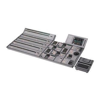
CENTER CONTROL PANEL PACK
CCP-8000
MKS-8010
HK-PSU02
MKS-8011
MKS-8014
MKS-8015B
MKS-8018
MKS-8019B
MKS-8022
MKS-8025
MKS-8027
MKS-8031JS
MKS-8033
MKS-8035
MKS-8075
SWC-5005
INSTALLATION MANUAL
1st Edition (Revised 7)
MKS-8010A
HK-PSU03
MKS-8013
MKS-8014B
MKS-8017
MKS-8018B
MKS-8020
MKS-8023
MKS-8025MS
MKS-8028
MKS-8031TB
MKS-8034DK
MKS-8040
MKS-8076
SWC-5010
MKS-8013B
MKS-8015
MKS-8017B
MKS-8019
MKS-8021
MKS-8024
MKS-8026
MKS-8030
MKS-8032
MKS-8034FB
MKS-8041
Advertisement
Table of Contents

Subscribe to Our Youtube Channel
Related Manuals for Sony CCP-8000


Summary of Contents for Sony CCP-8000
- Page 1 CENTER CONTROL PANEL PACK CCP-8000 MKS-8010 MKS-8010A HK-PSU02 HK-PSU03 MKS-8011 MKS-8013 MKS-8013B MKS-8014 MKS-8014B MKS-8015 MKS-8015B MKS-8017 MKS-8017B MKS-8018 MKS-8018B MKS-8019 MKS-8019B MKS-8020 MKS-8021 MKS-8022 MKS-8023 MKS-8024 MKS-8025 MKS-8025MS MKS-8026 MKS-8027 MKS-8028 MKS-8030 MKS-8031JS MKS-8031TB MKS-8032 MKS-8033 MKS-8034DK MKS-8034FB MKS-8035...
- Page 2 Serial No. 10001 and Higher HK-PSU03 Serial No. 10001 and Higher MKS-8023 Serial No. 10001 and Higher SWC-5005 Serial No. 10001 and Higher MKS-8024 Serial No. 10001 and Higher SWC-5010 Serial No. 10001 and Higher MKS-8025 Serial No. 10001 and Higher CCP-8000 IM...
- Page 3 Voor het verwijderen van de batterij kunt u contact When this product is installed in a rack and is opnemen met uw Sony onderhoudsdienst. supplied power from an outlet on the rack, please make sure that the rack does not overload the supply circuit.
-
Page 5: Table Of Contents
Installing the HK-PSU03 ................2-2 2-4. Installing the Operation Modules ..............2-3 2-4-1. Installing Modules ..............2-3 2-5. Connecting the MKS-8075/MKS-8076 ............2-8 2-5-1. How to Connect the MKS-8075 and the MKS-8076 ....2-8 2-5-2. How to Connect the Cables ............2-12 CCP-8000 IM... - Page 6 3-1-1. MKS-8010/8010A ..............3-1 3-1-2. MKS-8011 .................. 3-1 3-1-3. Main Panel/AUX Panel .............. 3-2 3-2. Periodic Inspection and Maintenance ............3-2 3-2-1. Periodic Inspection ..............3-2 3-2-2. Cleaning ..................3-3 3-3. About the Data Backup Capacitor ............... 3-3 CCP-8000 IM...
-
Page 7: Manual Structure
This manual describes the overview, system connection example and specifica- tions of options of CCP-8000..User’s Guide (Volume 1, Volume 2) (Supplied with CCP-8000) This manual describes the application and operation of CCP-8000..System Setup Manual (Available on request) -
Page 9: Installation
(2ME): Approx. 20 kg This unit does not come with a power cord. To get a power cord, please contact your local Sony Sales Prohibited locations for installation Office/Service Center. . Areas where the unit will be exposed do direct sunlight or any other strong lights. -
Page 10: Installation Space
1-3. Installation Space 1-3. Installation Space 1-3-1. External Dimensions System control unit MKS-8010 17.5 132.4 SYSTEM CONTROL UNIT MKS-8010 POWER A POWER B Unit : mm CCP-8000 IM... - Page 11 1-3. Installation Space System control unit MKS-8010A 43.6 63.1 Unit : mm CCP-8000 IM...
- Page 12 1-3. Installation Space Main panel/AUX panel/Menu panel MKS-8011 Unit : mm CCP-8000 IM...
- Page 13 1-3. Installation Space Menu panel MKS-8011 detailed dimensions 6-M3 Unit : mm CCP-8000 IM...
- Page 14 1-3. Installation Space Extension adaptor MKS-8075/Memory card/USB adaptor MKS-8076 Unit : mm CCP-8000 IM...
-
Page 16: Main Panel/Aux Panel Configuration Example
Extension Adaptor MKS-8075. INTEGRATED: Configuration that a module having width of 220 mm such as 10 Key Pad Module MKS-8026 is installed inside the panel. COMPACT: Configuration that the Compact Transition Module MKS-8027 / 8028 is going to be used. CCP-8000 IM... - Page 17 1139 1065.7 1291 1369.7 1217.7 324IO ASSY 316IO ASSY 332CO ASSY 324CO ASSY 316CO ASSY 1291 1217.7 1139 1369.7 1065.7 224IB ASSY 216IB ASSY 232CB ASSY 224CB ASSY 216CB ASSY 1139 1369.7 1065.7 1291 1217.7 Unit : mm CCP-8000 IM...
-
Page 18: Installation Space
. 3ME with AUX bus 1205 depth of 3 or more 32XPT separate type SEPARATED 1053 24XPT . 2ME 16XPT 1425 32XPT 1273 INTEGRATED 24XPT 6-M4 1121 16XPT 1351.7 32XPT 1199.7 COMPACT 24XPT 1047.7 16XPT 11.5 (Recommendation) Unit : mm 1-10 CCP-8000 IM... - Page 19 Details of the D portion 32XPT 1245.7 1369.7 1369.7 24XPT 1093.7 1217.7 1217.7 *1 : Product dimension COMPACT *2 : Product dimension on the installation surface 16XPT 941.7 1065.7 1065.7 *3 : Maximum external dimensions during installation Unit : mm 1-11 CCP-8000 IM...
- Page 20 Panel side <Vertical connection A, B> <Vertical connection C> (Maximum number of connections) (Maximum number of connections) 220 (Outside dimensions of case) 440 (Outside dimensions of case) 245±0.5 465±0.8 (19-inch rack width) 263±0.6 483±1.0 Unit : mm 1-12 CCP-8000 IM...
-
Page 21: Installing The Main Panel
5. Install all of the right and left module covers, and the caps (L) and (R) by reversing the steps 1 and 2 of Module cover removal. Cap (L) B3 x 6 B3 x 6 Cap (R) 1-13 CCP-8000 IM... -
Page 22: Installing The Aux Panel
. Screws (B5 x 8) : 4 pcs . Washer for M5 : 4 pcs (Sony part No. : 7-688-005-11) 1. Remove the panel covers (L) and (R). 2. Two persons or more should hold the AUX panel and install it into the control console. -
Page 23: Installing The Menu Panel
The menu panel MKS-8011 can be installed to the monitor arm compliant with VESA Standard using the adapter Connect the attached 50-pin cable to the menu panel, and supplied with CCP-8000. See the dimensions for installa- then perform the following steps. tion below. -
Page 24: Rack Mounting
If several units are mounted in a rack, it is recommended that a ventilation fan is installed to prevent temperature rise inside the rack. Maximum depth of adaptor : 750 mm Minimum depth of adaptor : 595 mm 1-16 CCP-8000 IM... - Page 25 8. Attach the front panel to the equipment. The rack tools are hooked on the rails as shown below. Rack tool Rack tool Rail Rail 6. Remove the front panel. (Refer to Section 2-1.) 1-17 CCP-8000 IM...
-
Page 26: Rack Mounting The Mks-8075 (Extension Adaptor)
MKS-8075/MKS-8076”. Tools required . Screws (B5 x 8) . Washers for M5 (Sony part No.: 7-688-005-11) When 2 adaptors are connected : Each 4 pcs When 4 adaptors are connected : Each 8 pcs When 6 adaptors are connected : Each 12 pcs When 8 adaptors are connected : Each 16 pcs 1. -
Page 27: Matching Connectors And Cables
Name Sony part No. MKS-8010 EXT PANEL1 to 3 D-sub 50-pin, Female Use the dedicated cable MKS-8010A MENU PANEL specified by Sony Corp. MAIN PANEL D-sub 25-pin, Female D-sub 25-pin, Male Connector 25-pin, Male 1-566-356-11 Junction Shell 25-pin 1-563-377-11 EXT DISPLAY... -
Page 28: Input/Output Signals Of Connectors
Pin No. Signal Name Function Ground Ground GPI IN 2 General-purpose input GPI IN 4 GPI IN 6 GPI IN 8 GPI OUT 1B General-purpose relay GPI OUT 2B output (B) (*1) GPI OUT 3B GPI OUT 4B 1-20 CCP-8000 IM... - Page 29 Video Blue No Connection Transmitted data (_) Ground Ground Ground Ground Ground Ground Ground Ground No Connection (*3) <CONTROLLER> : Indicates a controlling device. Ground No Connection No Connection HSYNC Horizontal Sync VSYNC Vertical Sync No Connection 1-21 CCP-8000 IM...
-
Page 30: Checks On Completion Of Installation
D919 S903 D480 D481 S480 D482 D483 ND480 CN482 ND481 D500 S482 D501 S610 ND610 CN612 ND611 D640 D610 D641 D611 S612 D612 D613 CN802 CPU-DK D317 D316 Module IF-844 D401 (COM0) D400 CN440 A side/Component side 1-22 CCP-8000 IM... - Page 31 D918 (A-5) : MAIN CPU status LED D482 (A-7) : CTRL CPU status LED Main CPU status indication. CTRL terminal communication IC status indication. Used only for production in the assembly factory. Used only for production in the assembly factory. 1-23 CCP-8000 IM...
- Page 32 CN802 (A-9) : JTAG connector CPU. Used only for production in the assembly factory. S611 (B-8) : Modes setting switch for COM1 CPU Used only for production in the assembly factory. Default setup when shipped from the factory is all OFF. 1-24 CCP-8000 IM...
- Page 33 In some machines in which the CPU-DR module is installed, the system reset may be activated. SW2 (A-2) : MODE switch 8-pin DIP switch Used only for production in the assembly factory. All switches are set to OFF for normal operation. 1-25 CCP-8000 IM...
- Page 34 E1 (B-3) : GND terminal Use this terminal as the earth point for measuring the respective check terminals. TP1 (A-2) : RX check terminal S-BUS communication line measuring terminal. TP2 (A-3) : TEST terminal Terminal for testing. 1-26 CCP-8000 IM...
- Page 35 LED flashes rotatingly when the initialization is completed and the COM1 CPU is booted correctly. D126 (D-2) : SBUS TX Flashes while transmitting the communication data to an equipment that is connected to the REMOTE terminal. 1-27 CCP-8000 IM...
- Page 36 Used to set the group ID for the CTRL, PERIPH and DATA terminals. Refer to the System Setup Manual for details. S108 (A-1) : STATION ID Used to set the REMOTE terminal. Refer to the System Setup Manual for details. 1-28 CCP-8000 IM...
- Page 37 CN4 (C-5) : USB Used to control the USB equipment such as memory card, USB module and others. CN5 (C-5) : COM3 The RS-232C interface that is used to control the touch- panel of the Menu Panel. 1-29 CCP-8000 IM...
- Page 38 DiskOnChip Memory Voltage Setup Address Setting JP18, JP20 COM3 Port RI & Voltage Setup DIO & Port 80 Setting JP19, JP21 COM2 Port RI & Voltage Setup Speaker Volume Control Setup JP10 AT and ATX Power Selection 1-30 CCP-8000 IM...
-
Page 39: System Connection
However, a single Ethernet switch can be used for connecting each LAN. For information about Ethernet switches that can be used in an MVS system, contact your local Sony Sales Office/Service Center. For detailed information about setting up the Ethernet switch, refer to the documentation supplied with the switch. -
Page 40: Connecting The Center Control Panel
. In order to install the MKS-8025/8025MS into the AUX panel, connect the DEVICE terminal of the MKS-8010/8010A to the HOST terminal of the AUX panel. . In order to install the MKS-8025/8025MS outside the system using the MKS-8076, connect the DEVICE terminal of the MKS- 8010/8010A to the HOST terminal of the MKS-8076. 1-32 CCP-8000 IM... -
Page 41: Installing The Options
Installing the Options 2-1. Opening and Closing the Front CCP-8000 Panel The CCP-8000 is shipped from the factory with the neces- sary modules (see below) already installed in the CCP-8000 in accordance with the system configuration for use. Opening/Closing The following options are available for the CCP-8000. -
Page 42: Installing The Hk-Psu02
5. Secure the HK-PSU02 with the two screws. 4. Insert the HK-PSU03 securely into the deep end. 5. Secure the HK-PSU03 with the two screws. Indicator HK-PSU02 B3 x 5 PSW3 x 6 Handle HK-PSU03 6. Reinstall the front panel. 6. Reinstall the front panel. CCP-8000 IM... -
Page 43: Installing The Operation Modules
Key Frame Module . MKS-8031JS Joystick Module . MKS-8031TB Track Ball Module (Refer to page 2-4.) . MKS-8032 DSK Fader Module . MKS-8033 Utility/Shotbox Module . MKS-8034DK DSK/FTB Module . MKS-8034FB FTB Module . MKS-8035 Key Control Module CCP-8000 IM... - Page 44 4. For MKS-8025MS, select a 1/2-wide case or 1/3-wide 6. Rotate the ball cover counter-clockwise and release the case according to the installing space in the CCP-8000. lock. Secure the ground terminal by the screw (PSW3 x 5) 7.
- Page 45 Installation to the main panel” to install the side that Module covers sits next to the adjoining operation module. Panel cover (L) Screws (with drop-safe) Operation module Operation module Panel cover (R) Screws (with drop-safe) Screws (with drop-safe) MKS-8075 Screws (with drop-safe) CCP-8000 IM...
- Page 46 MKS-8010/8010A is only one unit. . When you want to joint it, install MKS-8025 at the top end. (Refer to Fig. 1 (on page 2-8.)) Module covers Screws (with drop-safe) Screws Connector (with drop-safe) MKS-8025 MKS-8076 CCP-8000 IM...
- Page 47 PSW3 x 5 Ground terminal 1/2-wide case 6. Connect the harness of the MKS-8076 to the connector of the MKS-8025MS (new). 7. Install the MKS-8025MS (new) and fix it by tighten- ing the four screws (with drop-safe) on both sides. CCP-8000 IM...
-
Page 48: Connecting The Mks-8075/Mks-8076
Never panel it a table top. (The fixing method is same as that of the main panel.) Fig. 1 Number of connections : The position where the MKS-8076 can be connected CCP-8000 IM... - Page 49 Side plates BV3 x 10 BV3 x 10 BV3 x 10 Connecting plates A Adaptor cases Adaptor case BV3 x 10 Instruction given on the bottom of the cases CCP-8000 IM...
- Page 50 (A), (B) and (C) respective- ly. (refer to Fig. 2 (on page 2-11).) 6. Install the operation module and fix it by tightening Panel cover (L) the four screws on the sides. Panel cover (R) Stepped screws Stepped screws 2-10 CCP-8000 IM...
- Page 51 : Screw fixing position : Connecting plate screw fixing position Connection method (B) Connecting plate C Left side FRONT (Same as the right side) FRONT : Connecting plate screw fixing position : Screw fixing position Connection method (C) 2-11 CCP-8000 IM...
-
Page 52: How To Connect The Cables
MKS-8010/8010A to the HOST of the MKS-8076 using the USB cable supplied with the center control panel. 50-pin cable supplied with 50-pin cable supplied the center control panel with the MKS-8075 USB cable supplied with the center control panel MKS-8075 MKS-8075 MKS-8076 MKS-8075 2-12 CCP-8000 IM... -
Page 53: Service Overview
The power supply unit is probably defective. The MKS-8011 is Is the switch on the MKS-8011 lit? probably defective. 1. The backlight of the MKKS-8011 is probably burnt out. 2. LCD or the LCD drive circuit of the MKS-8011 is probably defective. CCP-8000 IM... -
Page 54: Main Panel/Aux Panel
Once in a month Filter Front panel on the MKS-8010/8010A Cleaning Once in two months Backup capacitor The menu CPU assembly in the MKS-8010 Replacement Once in five years The MPU-302B board (BT1301) in the MKS-8010A Replacement Once in five years CCP-8000 IM... -
Page 55: Cleaning
This may have an adverse effect on performance and life of the machine. Cleaning of the fan every month is recommended. Contact your local Sony Sales Office/Service Center for 3-3. About the Data Backup Capacitor information cleaning the fan. - Page 57 The material contained in this manual consists of information that is the property of Sony Corporation. Sony Corporation expressly prohibits the duplication of any portion of this manual or the use thereof for any purpose other than the operation or maintenance of the equipment described in this manual without the express written permission of Sony Corporation.
- Page 58 Printed in Japan Sony Corporation CCP-8000 (SY) E 2005. 3 16 B&P Company 3-206-009-08 ©2001...
Need help?
Do you have a question about the CCP-8000 and is the answer not in the manual?
Questions and answers