MIMAKI TS300P-1800 Operation Manual
Hide thumbs
Also See for TS300P-1800:
- Care and maintenance (16 pages) ,
- Print manual (11 pages) ,
- Product manual (44 pages)

Related Manuals for MIMAKI TS300P-1800


Summary of Contents for MIMAKI TS300P-1800
- Page 1 You can also download the latest manual from our website. MIMAKI ENGINEERING CO., LTD. URL: http://eng.mimaki.co.jp/ D202869-13 Original instructions...
-
Page 2: Table Of Contents
TABLE OF CONTENTS CAUTION ..................v DISCLAIMER OF WARRANTY ............v Requests ....................v FCC Statement (USA) ................v Interference to televisions and radios ........... v Foreword ..................v About usable ink ................... v On This Operation manual ..............v Safety Precautions ................vi Symbols .................... - Page 3 Setting a roll media................2-5 Using the tension bar to set the roll media ........2-8 Take-up device ................2-10 Setting leaf media................2-14 Changing the printing origin ............2-15 Preparing for the Heaters ............2-16 Changing the Temperature Settings for the Heaters....... 2-16 Test Printing ................2-16 Test Printing ..................
- Page 4 Setting a LANGUAGE ..............3-18 Setting Time ..................3-18 Setting Unit (Temperature/ Length)..........3-18 Setting a KEY BUZZER..............3-19 Setting the CONFIRM. FEED............3-19 Setting the SPACE FEED MODE............ 3-19 Set the network ................3-20 Setting event mail function .............. 3-20 Initializing the Settings..............
- Page 5 If a Waste Ink Tank Confirmation Message Appears ...... 4-17 Replace the waste ink tank with another ......... 4-18 Replacing the Cutter Blade ............. 4-19 Chapter 5 Troubleshooting Troubleshooting ................5-2 Power does not turn on ..............5-2 The machine does not start printing ..........5-2 Media get jammed / media is soiled ..........
-
Page 6: Caution
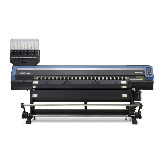
Congratulations on your purchase of MIMAKI color ink jet DISCLAIMER OF WARRANTY printer "TS300P-1800" . “TS300P-1800” is a color inkjet printer that can print on THIS LIMITED WARRANTY OF MIMAKI SHALL BE THE SOLE 1.8m-width media with sublimation dye ink (4-color, 6- AND EXCLUSIVE WARRANTY AND IS IN LIEU OF ALL color, 7-color and 8-color). -
Page 7: Safety Precautions
Check first that the machine no longer produces smoke, and then Examples of symbols contact your distributor or a sales office of MIMAKI for repair. • Never repair your machine by yourself since it is very Meaning dangerous for you to do so. -
Page 8: Cautions And Notes
When all the gloves are expended, purchase an Handling of media equivalent product on the market. • Use media recommended by MIMAKI to ensure reliable, high- quality printing. • Do not to touch the sharp edge of the blade when replacing the cutter. -
Page 9: Safety Interlock
• Never refill the ink pack and white ink cartridge with ink. Refilled ink cartridge can cause a trouble. Remember that MIMAKI assumes no responsibility for any damage caused by the use of •... -
Page 10: Warning Labels
Warning labels Warning labels Warning labels are stuck on the machine. Be sure to fully understand the warning given on the labels. If a warning label is illegible due to stains or has come off, purchase a new one from a distributor or our sales office. When the front cover is open When the maintenance cover is open... - Page 11 Warning labels Reorder Label M910931 M907833 M903239 M903330 M903405 M907935 M905811...
-
Page 12: Ec Declaration Of Conformity
Serial No. covered AABCDEEE AA: S4, B: 0 to 9, C: any alpha-numeric, D: any alphabet, EEE: 001 to 999 Manufacturer MIMAKI ENGINEERING CO.,LTD. 2182-3, Shigeno-otsu, Tomi, Nagano, 389-0512, JAPAN Authorised Compiler in the Community MIMAKI EUROPE B.V. Stammerdijk 7E 1112 AA Diemen, The Netherlands... -
Page 13: Before Use
Chapter 1 Before Use This chapter describes the items required to understand before use, such as the name of each part of the machine or the installation procedures. Moving This Machine ........1-2 Connecting Cables........1-9 Where to Install This Machine ..... 1-2 Connecting USB2.0 Interface Cable ....1-9 Working Environmental Temperature .. -
Page 14: Moving This Machine
Width Depth Height service office to move this machine. weight • When moving this machine, take care that it does TS300P-1800 3200mm 850mm 1857mm 213kg not receive a significant impact. • Be sure to lock the casters after moving of this machine. - Page 15 Chapter 1 Before Use Move this machine as shown in the figure. • For safety, be sure to operate it with 4 people or more. • Do not push the cover to move this machine since the cover may be broken. Lower the adjuster foot of the roll guide stay.
-
Page 16: Names Of Parts And Functions
Chapter 1 Before Use Names of Parts and Functions Front Side of the Machine Maintenance cover (upper) Open the cover in maintenance. Even when the power switch is off, keep all covers closed. Front cover Open the cover in setting of medias, taking of measures against jamming of medias or in Ink cartridges maintenance inside the station. -
Page 17: Rear Side And Right Side Of The Machine
Chapter 1 Before Use Rear Side and Right Side of the Machine Clamp lever (rear) Interlocks with the clamp lever in the font of this machine. Top blower Suppress upward floating of the ink mist that occurs during printing. Vent filter box Vents the ink mist that occurs during printing. -
Page 18: Operation Panel
Chapter 1 Before Use Operation Panel Use the operation panel to make settings for printing or operate this machine. Display Local <Setup 1> 12:00 Changes over the functions of the Displays the following items: heigth: 4.0mm function keys ([FUNC1]–[FUNC3]). width:1340mm width:1340mm •... - Page 19 Chapter 1 Before Use *2 : Functions assigned to [FUNC1] to [FUNC3] Contents of functions assigned to [FUNC1] to [FUNC3] are described below. Icon Contents Displays “MENU” for setting functions. Displays maintenance functions such as test print, cleaning, etc. Shifts to REMOTE from LOCAL and starts printing. Displays adjustment functions such as FEED COMP, DROP.POScorrect, etc.
-
Page 20: Media Sensor
Chapter 1 Before Use Media sensor Capping station The media sensor detects the presence of the media and the The capping station consists of the ink caps, the wiper for media length. cleaning the heads, etc. This machine has two media sensors on the platen (in the rear). The ink caps prevent the nozzles in the ink heads from drying up. -
Page 21: Connecting Cables
Chapter 1 Before Use Removing USB memory Connecting Cables If a USB memory module is inserted in the personal computer to which a TS300P machine is connected, click "Stop" in the "Safely Remove Hardware" window Connecting USB2.0 Interface Cable by following the instructions given there first and then remove the module. -
Page 22: Connecting The Power Cable
Chapter 1 Before Use If connecting via a switching hub Connecting the power cable Insert the power cable into an inlet of the machine. Inlet Switching hub Power cable Cable band Secure a cable band. • Secure the cable with the cable band attached to If the PC or device connected to the printer is not this machine. -
Page 23: Setting Ink
Chapter 1 Before Use Setting Ink (2) Tear off the seal on the connector of the 2L ink pack. Take out the 2L ink pack. • Take out the 2L ink pack and the IC chip from a small cardboard box. •... - Page 24 Chapter 1 Before Use Replacing the 2L Ink Pack Attach the 2L eco case to the base. • Ink is supplied to the printer connecting to the 2L Perform as follows when [INK END] or [INK NEAR END] eco case. is displayed on the display.
- Page 25 Chapter 1 Before Use For Ink cartridge lamps Mount the IC chip supplied with the replacement 2L ink pack. The condition of the ink cartridges set in the machine is confirmable with lamps located under the ink cartridges. • Be careful not to touch the metal part of the IC chip.
-
Page 26: Caution In Handling Of Ink Packs
Set the heater temperature to meet the in troubles. characteristics of the media. MIMAKI will not bear any responsibility for any • Pay attention to the expansion and damage caused by the use of the ink packs contraction of the media. -
Page 27: Menu Mode
Chapter 1 Before Use Menu mode This machine has 4 modes. Each menu mode is described below. NOT-READY mode This is the mode in which the media has not been detected yet. LOCAL mode Local mode is the mode for the drawing preparation state. All the keys are effective. - Page 28 Chapter 1 Before Use 1-16...
-
Page 29: Basic Operations
Chapter 2 Basic Operations This chapter describes procedures and setting methods for ink and media preparation, and printing. Workflow ............2-2 About head cleaning ........2-17 Perform head cleaning depending on the test Turning the Power ON/OFF ......2-3 printing result ..........2-17 Turning the Power ON ........ -
Page 30: Workflow
Chapter 2 Basic Operation Workflow Referring to “Turning the Power ON/OFF” Turning the Power ON/OFF P.2-3). Referring to “Setting a Media” ( P.2-4). Setting a Media Referring to “Test Printing” ( P.2-16). Test Printing Referring to “Head Cleaning” ( P.2-17). Head Cleaning Referring to “Printing Data”... -
Page 31: Turning The Power On/Off
Chapter 2 Basic Operation Turning the Power ON/OFF Turn the power off, by giving the key a long press. • Do not turn OFF the main power switch located Turning the Power ON on the side of the machine. • To use this machine again, press the [END/ POWER] key . -
Page 32: Setting A Media
Chapter 2 Basic Operation Setting a Media Loosen the height-adjusting screw in front, and press the key. This machine can be used with a roll media and leaf • Loosen the screws, rotating each by one turn of a media. standard screwdriver. -
Page 33: Setting A Roll Media
Chapter 2 Basic Operation Tighten the roll holder fixing screw. Setting a roll media • Check the Step 2 to 3 again. Set a roll media to the roll media hanger located on the back of this machine. Move the roll guide stay to match the Move the roll holder located in the back of position to set the media in. - Page 34 Chapter 2 Basic Operation (2) Insert the media between the platen and the Loosen the screw of the right side roll pinch roller. holder then insert the holder into the core • Pull the media out of the roll so that the of the roll media.
- Page 35 Chapter 2 Basic Operation Hold the media with the media press Close the front cover. gently. • Set the media so that no media sticks out from the Front cover right end pinch roller to the right side. • When using a thick media, remove the media press from the media before printing.
-
Page 36: Using The Tension Bar To Set The Roll Media
Chapter 2 Basic Operation Secure the media on the take-up device. Using the tension bar to set the roll P.2-10) media (1) Feed the media up to the core of the roll When setting media, read the following notes carefully. media of the take-up device by pressing [] . - Page 37 Chapter 2 Basic Operation right edge of the media after inputting media Entering the media remaining amount width. • When “Manual” is selected, proceed to Step 3. When [MEDIA RESIDUAL] of the machine setup is “ON” And when “Media width entering mode” is P.3-17 ), the screen for entering media remaining selected, proceed to below.
-
Page 38: Take-Up Device
Chapter 2 Basic Operation Setting the torque limiter Entering media thickness If the thickness input setting in [MEDIA DETECT] in The take-up device is provided with a torque limiter. P.3-17), set the machine setup is turned “ON” The take-up torque can be adjusted with the torque limiter. media thickness as follows: (The torque limiter is set to "Medium"... - Page 39 Chapter 2 Basic Operation Installing the counter weight for Number of counter weights you can attach adjusting the tension-bar weight (1) • The number of counter weights you can attach differs depending on the outer diameter after taking up the media. •...
- Page 40 Chapter 2 Basic Operation Installing the counter weight for Number of counter weights you can attach adjusting the tension-bar weight (2) • The number of counter weights you can attach differs depending on the outer diameter after taking up the media. •...
- Page 41 Chapter 2 Basic Operation (2) Attach it so that the tip of the shaft of the Replacing the torque limiter take-up device matches the surface of the motor direct-connection unit. When using the take-up unit and tension bar to take up the media, you can replace the torque limiter with the •...
-
Page 42: Setting Leaf Media
Chapter 2 Basic Operation When you want to change the take-up Setting leaf media method to the method using the Unlike roll media, leaf media does not need to be retained tension bar during printing with the roll holders. While printing using only the take-up device, you can change the take-up method to the method using the Open the front cover, and then raise the tension bar. -
Page 43: Changing The Printing Origin
Chapter 2 Basic Operation Push down the clamp lever and then close Changing the printing origin the front cover. The position of the printing origin can be changed. • Set the media straight. Moving the LED pointer to the changing position and deciding the position. -
Page 44: Preparing For The Heaters
Chapter 2 Basic Operation Preparing for the Heaters Test Printing Print a test pattern to check that there are no discharging Changing the Temperature Settings defects such as nozzle clogging (slight touching of ink or for the Heaters nozzle missing). You can change/save the temperature settings for the Relationship between head row and heaters with “Heater”... -
Page 45: Head Cleaning
Chapter 2 Basic Operation Head Cleaning Press the (TEST PRINT/CLEANING) , and then press the key in LOCAL. • The test pattern orientation screen will be displayed. About head cleaning Press to select the test pattern Check the printed test pattern result and perform cleaning orientation (SCAN DIR./ FEED DIR.). -
Page 46: Setting Of Media Correction
Chapter 2 Basic Operation Setting of Media Correction If the Positions of Dots Shift... Correct the media feed amount to match the type of media you are using. If the correction value is not appropriate, stripes may When the condition for printing (media thickness/ink type/ appear on the printed image, thus resulting in a poor etc.) has been changed, perform the following operation printing. -
Page 47: Printing Data
Chapter 2 Basic Operation Printing Data Start printing. • The printing speed may change, depending on the width of the set media or the position of the Starting a Printing Operation print origin even when the same data is printed. This is because of a difference in resolution. -
Page 48: Cutting A Media
Chapter 2 Basic Operation Cutting a media By using the keys on the operation panel, you can cut the media at any position. In Local, Press • It enters into the origin setting mode. • By pressing [] , feed the media to the cutting position. -
Page 49: Setup
Chapter 3 Setup This chapter describes the various setting of this machine. About SETUP MENU ........3-2 Setting the Display of Media Residual ..3-17 Setting the PG Drop Adjust......3-17 SETUP MENU table........3-3 Setting the Media Detection....... 3-17 Register the optimal print conditions to Setting the Drying Feed ...... -
Page 50: About Setup Menu
Chapter 3 Setup About SETUP MENU On SETUP MENU, you can set the print conditions to match the media you usually use. : Press this to select SETUP MENU, or to switch to the previous screen. Local <Setup 1> 12:00 : Press this to switch to the next screen. -
Page 51: Setup Menu Table
Chapter 3 Setup SETUP MENU table • For each setting item below, you can set it so that the machine may operate according to the value specified when you printed from your RIP software in the connected host PC. • Set Item : LOGICAL SEEK/ Overprint/ DRYING TIME/ MARGIN (LEFT and RIGHT)/ VACUUM FAN/ FEED SPEED •... -
Page 52: Register The Optimal Print Conditions To Match The Use
Chapter 3 Setup Copy the contents of SETUP 1 to 4 to Register the optimal print conditions [Temporary] to match the use You can use it with changing the part of registration contents of SETUP 1 to 4. In this machine, you will be able to register print Select “copy”... -
Page 53: Setting Of Media Correction
Chapter 3 Setup • Settings of Temporary will be saved to the location Press in LOCAL. (MENU) selected in step 5. Press the key several times to Press to select SETUP 1 to 4, end the setting. and press the key. -
Page 54: If The Positions Of Dots Shift
Chapter 3 Setup If the Positions of Dots Shift... Setting the HEATER When the condition for printing (media thickness/ink type/ Post-heater 1and Post-heater 2 are equipped on the etc.) has been changed, perform the following operation platen. to correct the ink drop position for bidirectional (Bi) Type of HEATER Function printing and obtain the proper printing result. -
Page 55: Setting The Optional Heater
Chapter 3 Setup Setting the Optional heater Setting of Logical Seek For details about the optional drying heater, refer to the The head’s operation varies depending on the LOGICAL separate document, “OPT-J0388 Heater 1800 Operation SEEK settings, as shown in the figure below. Manual.”... -
Page 56: Setting Of Overprint
Chapter 3 Setup Press to set drying Setting of Overprint time, and press the key. Sets the number of layers in which ink is to be applied. • Set the drying time for canning and after printing is completed. To enable the drying time specified Press in LOCAL. -
Page 57: Setting Of Vacuumfan
Chapter 3 Setup Setting of VacuumFan Setting of Feed Quality Sets the absorbability of the media. Change the speed and acceleration to feed a media By setting the absorption power to match the media, you during printing. If the media feed is not stable, change the can prevent print errors due to media rise-up. -
Page 58: Setting Of Maps4
Press the key several times to Setting of MAPS4 end the setting. The MAPS (Mimaki Advanced PassSystem) function to disperse the pass boundary to make the feeding stripes less visible. • Changing the MAPS4 settings may change the Setting MAPS4 Function (MANUAL) color tone. -
Page 59: Setting Auto Cleaning
Chapter 3 Setup Press the key . Setting Auto Cleaning You can set the machine so that it counts the number of printed files or the length or time after printing has been Press the key several times to completed, and performs cleaning automatically if required. end the setting. -
Page 60: Setting Pre-Feed
Chapter 3 Setup Setting Pre-feed The following effects can be expected by feeding back and forth the media before printing. • Prevent media from sticking to the various rollers and the platen of this machine. • If the wrinkle is shifted to the media, wrinkle reduction can be expected. -
Page 61: About Machine Setup Menu
Chapter 3 Mchine setting About MACHINE SETUP MENU Common settings are functions for using this machine easily. The following items can be set in machine setups. : Press this to select MACHINE SETUP MENU, or to switch to the previous screen. Local <Setup 1>... -
Page 62: Machine Setup Menu Table
Chapter 3 Mchine setting MACHINE SETUP MENU table Function name Set value Default Meaning When no operation has been performed for the NONE/ AUTO Power-off ( P.3-16) 30min set time, the power supply is automatically 10 ~ 600min turned “OFF”. For setting whether the take-up unit is used or TAKE-UP UNIT ON/ OFF... - Page 63 Chapter 3 Mchine setting Function name Set value Default Meaning Mail Delivery Set whether you send/ do not send the e-mail ON / OFF P.3-20) when the set event occurs. Print Start Set whether you send/ do not send the e-mail at ON / OFF Event the start of printing.
-
Page 64: Setting A Auto Power-Off
Chapter 3 Mchine setting Press to select a set value, and Setting a AUTO Power-off press the key. When no operation has been performed for the set time, • Set Value : Continuance/ Temporary the power supply is automatically turned “OFF”. Continuance : Switching ON / OFF the winding operation when Press... -
Page 65: Setting The Display Of Media Residual
Chapter 3 Mchine setting • Loosen the screen by referring to P.2-4 “Adjusting Setting the Display of Media Residual the Head Height”. Whether the screen displays the remaining amount of a With the head height set as 3 mm, tighten media is set. -
Page 66: Setting The Drying Feed
Chapter 3 Mchine setting Setting the Drying Feed Setting Time After printing, set the media feed length for drying You can set time of your country (time difference). uniformly to the end of the media. Press (MENU) (twice) • According to the position of your optional heater in LOCAL. -
Page 67: Setting A Key Buzzer
Chapter 3 Mchine setting Setting a KEY BUZZER Setting the SPACE FEED MODE You can turn off the buzzer sound when pressing the key. Change the feed mode of the margin included in the image data (the space of no data to be printed). If print data with much margin, set to “continuous”, then the print Press (MENU) -
Page 68: Set The Network
• Both of DHCP and AutoIP is OFF, you can set Mimaki’s product. To download the Network Configurator, DEFAULT GATEWAY/ DNS ADDRESS/ SUBNET check " Driver / Utility" on the download page at Mimaki MASK. For other than above, proceed to the Step Engineering (http://eng.mimaki.co.jp/download/). - Page 69 Chapter 3 Mchine setting Set the e-mail address Press to select “ON”, and press key. Press (MENU) (twice) Press the key several times to in LOCAL. end the setting. • MACHINE SETUP MENU will be displayed. Press (<<) . Set the event to send an event mail Press to select “EVENT MAIL”, and press the...
- Page 70 Chapter 3 Mchine setting Set the server Press , and press the key. • “PASSWORD” will be selected. Press (MENU) (twice) Press to set Pass in LOCAL. Word, and press the key. • MACHINE SETUP MENU will be displayed. • Press [][][][] to set the password to use for the authentication.
- Page 71 Chapter 3 Mchine setting Send a test e-mail Press the key. • The sent result is displayed. • If sending test e-mail has failed, an error code is Press (MENU) (twice) displayed. in LOCAL. Refer to the next page to solve the problem. •...
-
Page 72: Initializing The Settings
Chapter 3 Mchine setting Initializing the Settings You can return the setting of “SETUP”, “MAINTENANCE” and “MACHINE SETUP” to the status before shipment. Press (MENU) (twice) in LOCAL. • MACHINE SETUP MENU will be displayed. Press (<<) . Press to select “RESET”, and press the key. -
Page 73: About Nozzle Check Menu
Chapter 3 Confirming Machine Information About NOZZLE CHECK MENU Set operations concerning the nozzle missing detection function. : Press this to select INFORMATION MENU, or to switch to the previous screen. Local <Setup 1> 12:00 : Press this to switch to the next screen. heigth: 4.0mm width:1340mm width:1340mm... -
Page 74: Printing Check Flow
Chapter 3 Confirming Machine Informationa Printing Check Flow Nozzle check is conducted according to the following flow at the start of printing. • Turn the “Printing Check” setting ON to be enabled. • Only perform RETRY COUNT and Printing Check settings when the settings are enabled. nozzle check ... -
Page 75: Setting The Printing Check
Chapter 3 Confirming Machine Information Setting the Printing Check Setting the NOZZLE RECOVERY Select ON when you want to conduct nozzle check at the set this if you want to conduct automatic nozzle recovery start of online printing. when nozzle missing is detected. Press Press (MENU) -
Page 76: About Information Menu
Chapter 3 Confirming Machine Informationa About INFORMATION MENU The information of this machine can be confirmed. The following items can be confirmed as machine information. : Press this to select INFORMATION MENU, or to switch to the previous screen. 12:00 Local <Setup 1>... -
Page 77: Displaying The Information
Chapter 3 Confirming Machine Information Displaying the Information Press in LOCAL. (MENU) (4 times) • INFORMATION MENU will be displayed. Press to select a information. • Refer to the “INFORMATION MENU”, and select the information to be displayed. Press the key. - Page 78 Chapter 3 Confirming Machine Informationa 3-30...
-
Page 79: Maintenance
Chapter 4 Maintenance This chapter describes the items required to use this machine more comfortably, which are the methods for the daily care, the maintenance of the ink cartridges etc. Maintenance ..........4-2 Reset the set value ........4-14 Check the condition for which nozzle Precautions for Maintenance ...... -
Page 80: Precautions For Maintenance
Chapter 4 Maintenance Maintenance Cleaning the Exterior Surfaces When the exterior surfaces of the machine are stained, Maintain the machine regularly or as necessary so that its dampen a soft cloth with water or a neutral detergent accuracy will be maintained and it can continue to be diluted with water, squeeze it, and wipe the surfaces with used for a long time. -
Page 81: Cleaning The Media Press
Chapter 4 Maintenance When cleaning the sensor on the lower surface of the Cleaning the Media Press head is cleaned, move the carriage to the left end by the operations of step 1 of P.4-12 “Cleaning the Ink Head and When the media press is covered with lint, dust, etc., a the Area around It”, and clean it. -
Page 82: About Maintenance Menu
Chapter 4 Maintenance About MAINTENANCE MENU This provides various settings for doing maintenance on the machine. The following items can be set in Maintenance settings. : Press this to select MAINTENANCE MENU, or to switch to the previous screen. 12:00 Local <Setup 1>... -
Page 83: Maintenance Menus At-A-Glance
Chapter 4 Maintenance MAINTENANCE MENUs at-a-glance Item Set value Meaning For carrying out maintenance on the carriage and station periphery. CARRIAGE OUT Moves the carriage out, for carrying out cleaning of the cap periphery, P.4-6) head, wipers, etc. NOZZLE WASH Soaks the nozzle surfaces in maintenance cleaning fluid, for carrying 1 to 99min P.4-7) -
Page 84: Maintaining The Capping Station
Chapter 4 Maintenance Maintaining the Capping Remove the wiper. Station • Pull out the wiper by holding the protrusions at its both ends. Maintain the ink cap, wiper, etc. located in the capping station. (SATION MAINT.) Projection • To keep the nozzle status normal, perform wiper cleaning frequently. -
Page 85: Washing The Head Nozzle
Chapter 4 Maintenance Press the key after the cleaning. • Do not remove the wiper cleaner from the bracket. • Only clean the front surface on the wiper cleaner's wiper. (You do not need to clean the rear surface.) • Do not remove the absorbent material in the Close the front cover then press the absorbent case. - Page 86 Chapter 4 Maintenance If a message is displayed, open the front • After cleaning the wiper, check to make sure the cap slider is not tilted. cover and check the amount of cleaning If it is tilted, move the slider block left and right to solution in the cap.
-
Page 87: Washing The Ink Discharge Passage
Chapter 4 Maintenance If a END message is displayed, open the Washing the Ink Discharge Passage front cover and check the amount of Wash the ink discharge passage regularly(about once a cleaning solution in the cap. week) to prevent the head nozzles from clogging due to ink coagulation inside the passage. -
Page 88: When The Machine Is Not Used For A Long Time
Chapter 4 Maintenance (3) Insert it in the original position by holding the When the Machine Is Not Used for a projections at both ends of the wiper. Long Time Projection When the machine is not going to be used for a week or more, use the cleaning function for custody to clean the head nozzles and ink discharge passage.After this, keep the machine in custody. - Page 89 Chapter 4 Maintenance Press the key. Close the front cover and press the key. • The nozzles are washed. • When the nozzles have been completely washed, the head moves to the maintenance position. Fill up the cap with cleaning solution for maintenance....
-
Page 90: Cleaning The Ink Head And The Area Around It
Chapter 4 Maintenance Cleaning the Ink Head Wipe ink sticking to the side of the head off with a clean stick. and the Area around It • Never rub the nozzles. Because head employs very precise mechanism, due care needs to be taken when it is cleaned. -
Page 91: Nozzle Recovery Function
Chapter 4 Maintenance Nozzle Recovery Function Register the Nozzle number that needs NOZZLE RECOVERY and press the NOZZLE RECOVERY: When nozzles missing can not be key. improved at specific points, other good nozzles can be (1) Select the registration number from 1 to 10 used as alternatives for printing. -
Page 92: Reset The Set Value
Chapter 4 Maintenance Press Reset the set value • Begin to check if nozzle recovery at the set printing conditions can be done. Press (MENU) • When the check is completed, the judgment result in LOCAL. is displayed on the screen. •... -
Page 93: Automatic Maintenance Function
Chapter 4 Maintenance Automatic Maintenance Setting the Tube Wash Intervals Function For setting the interval at which washing of the ink tubes will be carried out, in order to prevent ink clogging due to To use this machine comfortably, you can set various coagulation of ink inside the ink tubes. -
Page 94: Suspend The Nozzle Cleaning
Chapter 4 Maintenance Fill up Ink Suspend the nozzle cleaning Supplies ink to correct nozzle clogging. When you want to work as such a printing during the nozzle cleaning, you can interrupt the nozzle cleaning. Press (MENU) • If the nozzle cleaning is interrupted, run the head in LOCAL. -
Page 95: If A Waste Ink Tank Confirmation Message Appears
Chapter 4 Maintenance Press the key. If a Waste Ink Tank Confirmation • The carriage will move onto the platen. Message Appears Ink used in head cleaning, etc. is stored in the waste ink tank on the lower right side of the machine.This machine counts the accumulated amount of discharged ink. -
Page 96: Replace The Waste Ink Tank With Another
Chapter 4 Maintenance Replace the waste ink tank. Replace the waste ink tank with another (1) Prepare a new waste ink tank (SPC-0117). When the waste ink tank becomes full, carry out the (2) Insert the waste ink tank by holding a handle procedure below to replace the waste ink tank, and in the of the tank. -
Page 97: Replacing The Cutter Blade
Chapter 4 Maintenance Replace the cutter unit by the carriage. Replacing the Cutter Blade (1) Loosen the screw of the cutter unit. The cutter blade is consumable.When the cutter blade (2) Remove the cutter unit. gets dull, replace it with a new one (SPA-0107). (3) Mount a new cutter unit. - Page 98 Chapter 4 Maintenance 4-20...
-
Page 99: Troubleshooting
Chapter 5 Troubleshooting This chapter describes the corrective measures to be taken for a phenomenon suspected to be trou- ble and the procedures to clear the error number displayed on the LCD. Troubleshooting ................5-2 Power does not turn on ..............5-2 The machine does not start printing .......... -
Page 100: Power Does Not Turn On
Troubleshooting Take appropriate actions as described below before taking the trouble as a failure. If still the problem is not solved after troubleshooting, contact your dealer or an office of MIMAKI. Power does not turn on In most cases, this is due to improper connection of the power cable for the machine or computer. Check that the power cable is connected properly. -
Page 101: The Heater's Temperature Will Not Rise To The Set Level
• Once cartridge trouble is displayed, do not leave the ink pack without replacing it for a long time; otherwise, the machine will lose the nozzle clogging prevention function. If nozzles are clogged, the machine must be repaired by MIMAKI's service engineer. Displaying the description of ink IC trouble The contents of IC error are confirmable by the following operations. -
Page 102: Warning / Error Messages
Chapter5 Troubleshooting Warning / Error Messages If some trouble occurs, the buzzer sounds and the display shows a corresponding error message. Take an appropriate remedy for the displayed error. Warning messages Errors when performing operations Message Cause Solution Operation cannot be performed because INVAILD OPERATION •... - Page 103 Chapter5 Troubleshooting Message Cause Solution The maintenance washing liquid car- tridge is not set. Wash liqid cartridge none Wiper washing and pump tube washing Set the maintenance washing liquid cartridge. cannot be executed. (Auto maintenance operation) There is no remaining maintenance washing liquid.
- Page 104 Chapter5 Troubleshooting Ink Error Ink error is displayed also in the local guidance. ( P.3-29) Message Cause Solution • Remove the ink IC chip generating the warn- ing once and install it again. The IC chip of the ink pack cannot be WRONG INK IC •...
-
Page 105: Error Messages
Chapter5 Troubleshooting Error messages When an error message is displayed, eliminate the error according to the chart below. If the same error message appears again, contact your dealer or an office of MIMAKI to call for service. Message Cause Solution ERROR 108 Head temperature control is defective. - Page 106 Chapter5 Troubleshooting Message Cause Solution ERROR 18e FLS NOT COMP An error was detected in the waveform being printed. ERROR 18f OFFSET START An error was detected in the waveform ERROR 18f OFFSET END being printed. ERROR 1d9 An error occurred in the main PCB . Main PCB V48-1 ERROR 1ce SLIDER PCB V24...
- Page 107 Chapter5 Troubleshooting Message Cause Solution ERROR 304 USB INIT ERR An error occurred in the communication of USB. ERROR 305 USB TIME OUT • Turn off the main power to the machine and turn it on after a while. An error occurred during the access to ERROR 307 •...
- Page 108 Chapter5 Troubleshooting Message Cause Solution • Turn the main power OFF, wait a while, and then turn it ON again.If the same error mes- ERROR 528 Pump sensor detection error PUMP MOTOR SENSOR sage appears, contact our service desk or your local distributor to call for service.
- Page 109 Chapter5 Troubleshooting Message Cause Solution • Check the state of the nozzles, and if there are frequent nozzle missing and ink droplet misalignment, conduct cleaning to restore. ERROR 656 Sensor sensitivity adjustment has failed. • If the same error message still appears after NCU SN ADJST restoring the state of the nozzles, contact our service desk or your local distributor to...
- Page 110 Chapter5 Troubleshooting Message Cause Solution • Turn off the main power to the machine and turn it on after a while. An error occurred in the main PCB ERROR 04 • If the same error message appears again, PARAM ROM FROM.
-
Page 111: Appendix
Chapter 6 Appendix This chapter contains the lists of the specifications and functions of this machine. Specifications ..................6-2 Machine specifications ..............6-2 Ink specifications ................6-3 Setting orders depending on ink type ..........6-4 Setting orders of ink cartridges ............6-4 Sheet for inquiry ................6-5... -
Page 112: Specifications
Chapter6 Appendix Specifications Machine specifications Item TS300P-1800 Method Drop-on-demand piezoelectric print heads Print head Specification 4-Head Inline Printing mode (scan x feed) 360×360dpi/ 540×360dpi/ 720×720dpi/ 720×1080dpi/ 720×1440dpi Usable inks 9 colors (Y,M,Bl,K,LBl,Lm,Lk,FP,FY) Supplying from ink packs through tubes. Ink supply... -
Page 113: Ink Specifications
Chapter6 Appendix Item TS300P-1800 Power AC100 - 120V/ 200 - 240V 12A/8A 50/60Hz Power consumption 1440W(AC100 - 120V), 1920W (AC 200 - 240V) Available temp. 20 °C to 30 °C Humidity 35 to 65% Rh (No condensation) Guaranteed temp. 20 °C to 25 °C... -
Page 114: Setting Orders Depending On Ink Type
Chapter6 Appendix Setting orders depending on ink type The setting value and the setting orders of the ink cartridges differ depending on the ink type you use. Setting orders of ink cartridges The orders of ink cartridges set in the ink station differ depending on the ink set you use. •... -
Page 115: Sheet For Inquiry
Chapter6 Appendix Sheet for inquiry Use this sheet for troubles and abnormal functions of the machine. Fill in the following necessary items, and then fax the sheet to our sales office. Company name Person in charge Telephone number machine model Operating OS Machine information Error message... - Page 116 Chapter6 Appendix...
- Page 117 TS300P-1800 Operation Manual August, 2016 MIMAKI ENGINEERING CO.,LTD. 2182-3 Shigeno-otsu, Tomi-shi, Nagano 389-0512 JAPAN D202869-13-25082016...
- Page 118 FW : 1.80 © MIMAKI ENGINEERING CO., LTD.2016...
Need help?
Do you have a question about the TS300P-1800 and is the answer not in the manual?
Questions and answers