Table of Contents
Advertisement
Quick Links
Advertisement
Table of Contents

Related Manuals for Omron iX4


Summary of Contents for Omron iX4
- Page 1 650 H/HS and 800 H/HS Robot with EtherCAT User's Manual I656-E-01...
- Page 2 Copyright Notice The information contained herein is the property of OMRON, and shall not be reproduced in whole or in part without prior written approval of OMRON. The information herein is subject to change without notice and should not be construed as a commitment by OMRON. The documentation is periodically reviewed and revised.
-
Page 3: Table Of Contents
Releasing an E-Stop 2.3 Safety Precautions User's Responsibilities General Hazards Qualification of Personnel 2.4 Robot Behavior Hardstops Limiting Devices Singularities 2.5 Intended and Non-intended Use 22793-000 Rev. A iX4 650 H/HS and 800 H/HS Robot with EtherCAT User’s Manual (Cat. No. I656) - Page 4 Using a User-Supplied Control Panel Remote Pendant Usage 3.7 Setting the EtherCAT Node ID Setting the EtherCAT Node ID Using Hardware Switches 3.8 Installing or Removing Ball Stud Locks iX4 650 H/HS and 800 H/HS Robot with EtherCAT 22793-000 Rev. A User’s Manual (Cat. No. I656)
-
Page 5: Ix4 650 H/Hs And 800 H/Hs Robot With Ethercat
4.5 Grounding the Robot System Grounding the iX4-650H/800H Robot Base Grounding the iX4-650HS/800HS Robot Base Grounding Robot-Mounted Equipment 4.6 Installing a Cable Inlet Box for iX4-650H/800H Robots 4.7 Installing a Cable Inlet Box for iX4-650HS/800HS Robots Assembling the Cable Inlet Box Connecting the Cables Installing the Cable Inlet Box 4.8 Attaching the Cable Tray... - Page 6 Configuration 6.11 Replacing Outer Arm Spring Assemblies 6.12 Replacing a Ball Joint Socket Insert 6.13 Replacing the iCS-ECAT Unit for an iX4-650H/800H Robot Removing the iCS-ECAT Chassis Installing a New iCS-ECAT Chassis iX4 650 H/HS and 800 H/HS Robot with EtherCAT 22793-000 Rev.
-
Page 7: Ix4 650 H/Hs And 800 H/Hs Robot With Ethercat
Table of Contents 6.14 Replacing the iCS-ECAT Unit for an iX4-650HS/800HS Robot Removing the iCS-ECAT Chassis from an iX4-650HS/800HS Robot Installing a new iCS-ECAT Chassis 6.15 Remove and Replace a MicroSD Card Removing a MicroSD Card from an iCS-ECAT Replacing a MicroSD Card in an iCS-ECAT Chapter 7: Technical Specifications 7.1 Robot Physical Dimension Drawings... -
Page 9: Chapter 1: Introduction
Chapter 1: Introduction This manual contains information that is necessary to install and use an iX4 robot. Please read this manual and make sure you understand the functionality, installation, and performance of the robot before attempting to use it. 1.1 Related Manuals Use the following related manuals for reference. -
Page 10: Intended Audience
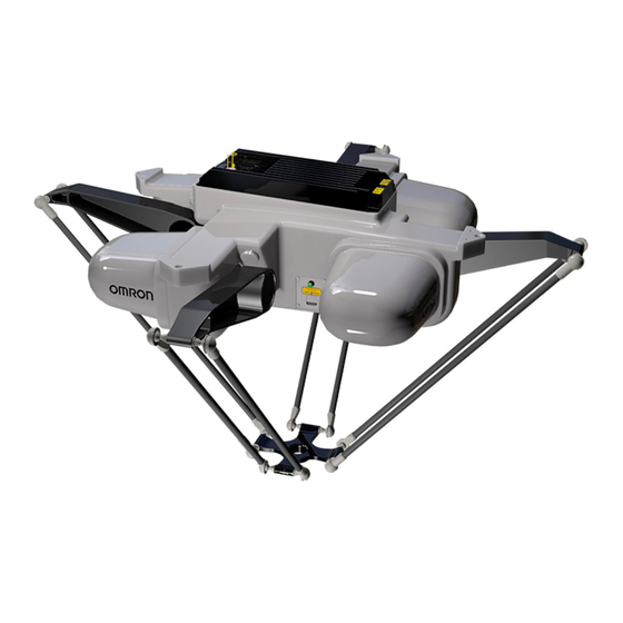
Personnel in charge of managing FA systems and facilities. 1.3 Robot Overview The iX4 is a four-arm parallel robot. Servo motors in the robot base control movement of the robot platform through mechanical links and arms. A tool flange is provided on the bottom of the platform for mounting end-of-arm tooling. -
Page 11: Major Differences Between Ix4-650H/800H And Ix4-650Hs/800Hs Robots
Note that either anodized aluminum or stainless steel platforms can be used on the iX4-650H and iX4-800H robots. The iX4-650HS and iX4-800HS are only available with stainless steel platforms. -
Page 12: Robot Amplifier And Controller
The iCS-ECAT unit receives V+ commands from the NJ-series Robot Integrated CPU Unit and processes these commands to execute robots motions and other functions. iX4 650 H/HS and 800 H/HS Robot with EtherCAT 22793-000 Rev. A User’s Manual (Cat. No. I656) - Page 13 VAC, 24 VDC), communications, and other peripheral devices such as a pendant, IO Blox, or a Front Panel. Figure 1-3. iCS-ECAT Robot Interface Panel Table 1-3. iCS-ECAT Robot Interface Panel Descriptions Item Description AC Power Supply Connector 22793-000 Rev. A iX4 650 H/HS and 800 H/HS Robot with EtherCAT User’s Manual (Cat. No. I656)
- Page 14 XBELTIO XIO Connector Used for user I/O signals for peripheral devices. Refer to Basic System Cable Layout on page 63 for more information. iX4 650 H/HS and 800 H/HS Robot with EtherCAT 22793-000 Rev. A User’s Manual (Cat. No. I656)
-
Page 15: Robot Base
Desctription Description Inner Arm Outer Arms Ball Joint Socket Ball Joint Socket Insert Ball Joint Stud Pressed Pin Outer Arm Springs Spring Holder 22793-000 Rev. A iX4 650 H/HS and 800 H/HS Robot with EtherCAT User’s Manual (Cat. No. I656) -
Page 16: Inner Arms
The platform converts the motion of the robot motors into Cartesian motion and, for all but the fixed platform, theta rotation of the tool flange. The iX4 robot supports four models of platforms, depending on the amount of Theta rotation and inertia needed. Each model is available in either Anodized Aluminum or Stainless Steel. - Page 17 Figure 1-7. P32 Platform P34 Platform P34 platform has a rotation range of ±185°. The tool flange is mounted on one of the pivot links. 22793-000 Rev. A iX4 650 H/HS and 800 H/HS Robot with EtherCAT User’s Manual (Cat. No. I656)
-
Page 18: Robot Motions And Obstacles
Includes terminals for user wiring and I/O status LEDs. Connects to the XIO connector with 2m cable. IO Blox (p/n 30410-220) IO Blox units extend the robot's capabilities by providing expandable I/O capacity. iX4 650 H/HS and 800 H/HS Robot with EtherCAT 22793-000 Rev. A User’s Manual (Cat. No. I656) -
Page 19: T20 Pendant
T20 pendant. IMPORTANT: The T20 pendant can only communicate with the robot it is dir- ectly connected to. 22793-000 Rev. A iX4 650 H/HS and 800 H/HS Robot with EtherCAT User’s Manual (Cat. No. I656) -
Page 20: Ipc Application Controller
Emergency stop / disable robot high power. Additional Information: Design of the factory-supplied Front Panel E-stop is in accordance with the requirements of IEC 60204-1 and ISO 13849. iX4 650 H/HS and 800 H/HS Robot with EtherCAT 22793-000 Rev. A User’s Manual (Cat. No. I656) -
Page 21: Optional Cables
The optional XBELT IO Adapter cable splits the XBELTIO port on the robot interface panel into a belt encoder branch and an IO Blox branch, and an RS- 232 branch. 22793-000 Rev. A iX4 650 H/HS and 800 H/HS Robot with EtherCAT User’s Manual (Cat. No. I656) - Page 22 The optional XIO cable is for connecting an XIO Termination Block to the XIO port on the iCS-ECAT robot interface panel. For addtional details, refer to XIO Termination Block on page 71. iX4 650 H/HS and 800 H/HS Robot with EtherCAT 22793-000 Rev. A User’s Manual (Cat. No. I656)
- Page 23 Violet/White Output 1 Pink Output 2 Pink/Black Output 3 Light Blue Output 4 Light Blue/Black Output 5 Light Green Output 6 Light Green/Black 22793-000 Rev. A iX4 650 H/HS and 800 H/HS Robot with EtherCAT User’s Manual (Cat. No. I656)
-
Page 24: Cable Inlet Box
Pin 19 Pin 26 Cable Inlet Box The optional cable inlet box can be used to increase the iX4-650H/800H robot's IP rating to IP65. The part number of the cable inlet box is 08765-000. NOTE: The optional cable inlet box (for the iX4-650H/800H) is not USDA com- pliant. -
Page 25: Ball Stud Locks
A ball stud lock kit (16 locks) is available as part number 09824-000. Additional Information: Refer to Installing or Removing Ball Stud Locks on page 61 for more information. 22793-000 Rev. A iX4 650 H/HS and 800 H/HS Robot with EtherCAT User’s Manual (Cat. No. I656) - Page 26 1.4 Robot Options Figure 1-14. Ball Stud Locks iX4 650 H/HS and 800 H/HS Robot with EtherCAT 22793-000 Rev. A User’s Manual (Cat. No. I656)
-
Page 27: Chapter 2: Safety
WARNING: PERSONAL INJURY OR PROPERTY DAMAGE RISK If mounted incorrectly, the robot can fall over and cause serious injury to per- sonnel or damage to itself or other equipment. 22793-000 Rev. A iX4 650 H/HS and 800 H/HS Robot with EtherCAT User’s Manual (Cat. No. I656) -
Page 28: Special Information
After the E-Stop button has been manually released, the robot will wait until the motors are manually enabled. Once the motors are enabled, the robot will wait two seconds and then resume commanded motion. iX4 650 H/HS and 800 H/HS Robot with EtherCAT 22793-000 Rev. A User’s Manual (Cat. No. I656) -
Page 29: Safety Precautions
The robot must be well maintained, so that their control and safety functions continue to work properly. General Hazards IMPORTANT: The following situations could result in injury or damage to the equipment. 22793-000 Rev. A iX4 650 H/HS and 800 H/HS Robot with EtherCAT User’s Manual (Cat. No. I656) -
Page 30: Qualification Of Personnel
It is the end-user’s responsibility to ensure that all personnel who will work with or around robots have attended an appropriate Omron training course and have a working knowledge of the system. The user must provide the necessary additional training for all personnel who will be working with the system. -
Page 31: Limiting Devices
Refer to Cleaning iX4-650H/800H Robots on page 118 and Cleaning iX4- 650HS/800HS Robots on page 120 for more information. The robot`s platform and outer arms are IP67 rated. The base of the iX4-650H/800H robots is IP65 rated, and for the iX4-650HS/800HS robots, the rating is IP66. -
Page 32: Additional Safety Information
Robot Safety Guide (Cat. No. I590) The Robot Safety Guide (Cat. No. I590) that is shipped with every robot system provides detailed information on safety for OMRON robots. It also gives resources for information on relevant standards. Emergency Stop Circuit and Buttons The E-Stop provided complies with ISO 10218-1 (Clause 5.5.2), with stop category 1 (per IEC... -
Page 33: T20 Manual Control Pendant (Option)
For information about disposal of your old equipment, contact your local OMRON representative. 22793-000 Rev. A iX4 650 H/HS and 800 H/HS Robot with EtherCAT User’s Manual (Cat. No. I656) -
Page 35: Chapter 3: Robot Installation
Chapter 3: Robot Installation This chapter provides information about installing the iX4 robot and other necessary equip- ment. 3.1 Robot Installation Overview This section provides an overview of the basic tasks that are required to install the robot. WARNING: Robot installation must be completed before optional equipment can be installed. - Page 36 A modal ana- lysis should be performed on the frame design with each robot approximated as a 120 iX4 650 H/HS and 800 H/HS Robot with EtherCAT 22793-000 Rev. A...
-
Page 37: Frame Orientation
If the frame pad does not cover the entire robot pad, the gasket will not seal properly. The design of the iX4- 22793-000 Rev. A iX4 650 H/HS and 800 H/HS Robot with EtherCAT User’s Manual (Cat. -
Page 38: Robot-To-Frame Considerations
The robot mounts in four locations, as detailed in the drawings. For an iX4-650H/800H robot, the holes are tapped for an M16 x 2.0 bolt. The robot may be mounted from the top or bottom of the frame. A crane or forklift should be used to position the robot. -
Page 39: Gussets
(15 mm thickness is adequate for most situ- ations). 3.3 Mounting the Robot Base This section describes mounting details for the iX4 robot base. WARNING: PERSONAL INJURY OR PROPERTY DAMAGE RISK Only allow qualified service personnel to install or service the robot. - Page 40 650HS/800HS Mounting Hardware on page 41 to proceed with the mounting procedure. Installing iX4-650H/800H Mounting Hardware Fastening the iX4-650H/800H to the mounting frame can be achieved by either threading bolts into the robot base or inserting bolts through the base and securing with nuts. All mounting bolt types require split lock and flat washers.
- Page 41 USDA compliance. USDA requires that all exposed screws be sealed with a gasket, which must be compressed to specific stand- ards. To achieve this, the iX4-650HS/800HS robot mounting bolts use a spacer that fits inside a compressible sealing gasket.
-
Page 42: Installing The Platform
ISO Property Class 5.8 98 N·m Use the following procedure to fasten the iX4-650HS/800HS robot to the mounting frame. 1. Verify that the gaskets between the robot pads and the mounting frame are in their grooves in the pads, and completely covered by the mounting frame pads. -
Page 43: Attach The Outer Arms
Outer arm pairs are shipped assembled. Each pair has two springs and two spring retainers at each end. CAUTION: PINCH RISK Ball joints are spring-loaded. Be careful not to pinch your fingers. 22793-000 Rev. A iX4 650 H/HS and 800 H/HS Robot with EtherCAT User’s Manual (Cat. No. I656) - Page 44 This requires the least stretch- ing of the spring to attach the ball joints. iX4 650 H/HS and 800 H/HS Robot with EtherCAT 22793-000 Rev. A User’s Manual (Cat. No. I656)
- Page 45 Figure 3-7. Springs Seated Properly After all outer arms are fastened to both the inner arms and platform, the platform installation procedure is complete. 22793-000 Rev. A iX4 650 H/HS and 800 H/HS Robot with EtherCAT User’s Manual (Cat. No. I656)
-
Page 46: Outer Arm Attachment Procedure
Move the platform and outer arm pair to the left as you slip the left ball joint socket over the corresponding ball stud. iX4 650 H/HS and 800 H/HS Robot with EtherCAT 22793-000 Rev. A User’s Manual (Cat. No. I656) -
Page 47: Installing The Front Panel
DANGER: A remote High Power push-button must be installed outside of the robot's workspace. Mounting the Front Panel Use dimensions provided in the figure below when mounting the Front Panel. 22793-000 Rev. A iX4 650 H/HS and 800 H/HS Robot with EtherCAT User’s Manual (Cat. No. I656) -
Page 48: Connecting The Front Panel
XSYSTEM Cable Extension Cable iCS-ECAT Interface Panel Figure 3-11. Front Panel Connections Front Panel Schematic Use the following diagram to understand all Front Panel electrical connections. iX4 650 H/HS and 800 H/HS Robot with EtherCAT 22793-000 Rev. A User’s Manual (Cat. No. I656) -
Page 49: Installing User-Supplied Safety Equipment
Failure to install suitable safety equipment could result in injury or death. Additional Information: Refer to the Robot Safety Guide (Cat. No. I590) for more information. 22793-000 Rev. A iX4 650 H/HS and 800 H/HS Robot with EtherCAT User’s Manual (Cat. No. I656) -
Page 50: Contacts On Xusr Connector
Contacts are closed in Automatic mode CH 1 10, 23 Manual or Automatic indication Contacts are closed in Automatic mode CH 2 11, 12, No connection 13, 24, iX4 650 H/HS and 800 H/HS Robot with EtherCAT 22793-000 Rev. A User’s Manual (Cat. No. I656) -
Page 51: Contacts On Xfp Connector
Do not inadvertently connect 24 VDC signals to these pins as that will damage the elec- tronics. NOTE: Underwriters Laboratory evaluated the system with an OMRON Front Panel. Using a substitute front panel could void UL compliance. Remote Pendant Signals on the XMCP Connector Use the information in the following table to understand the remote pendant signals provided on the XMCP connector. -
Page 52: E-Stop Circuits On Xusr And Xfp Connectors
Shield Shield GND 24 VDC No connection E-Stop Circuits on XUSR and XFP Connectors The following figure shows E-Stop circuits for the system. iX4 650 H/HS and 800 H/HS Robot with EtherCAT 22793-000 Rev. A User’s Manual (Cat. No. I656) - Page 53 (XPND-26) (XPND-25) XSYSTEM-29 (XUSR-18) XSYSTEM-44 (XUSR-19) XSYSTEM-26 (XUSR-8) XSYSTEM-10 (XUSR-7) XSYSTEM-25 (XUSR-20) XSYSTEM-40 (XUSR-21) Figure 3-13. E-Stop Circuit on XUSR and XFP Connectors 22793-000 Rev. A iX4 650 H/HS and 800 H/HS Robot with EtherCAT User’s Manual (Cat. No. I656)
-
Page 54: Emergency Stop Circuits
User E-Stop contacts, so they will not indicate the status of the Line E-Stop, MCP ENABLE, or the Muted Safety gate. If you have a specific need for this function, iX4 650 H/HS and 800 H/HS Robot with EtherCAT 22793-000 Rev. A... - Page 55 Chapter 3: Robot Installation contact your local OMRON support for information on alternate indicating modes. Two pairs of pins on the XUSR connector (pins 7, 20 and 8, 21, Figure 3-13. ) provide voltage- free contacts, one for each channel, to indicate whether the E-Stop chain on that channel, as described above, is closed.
-
Page 56: Remote Manual Mode
1 A. WARNING: PERSONAL INJURY HAZARD If you suspended any safeguards, you must return them to full functionality before selecting Automatic Mode. iX4 650 H/HS and 800 H/HS Robot with EtherCAT 22793-000 Rev. A User’s Manual (Cat. No. I656) -
Page 57: Remote High Power On / Off Control
Pins 6, 14 and 5, 13 of the XFP connector provide this remote capability. Pins 5, 13 provide power for the lamp, +5 VDC and ground, respectively. Pins 6, 14 are inputs for voltage-free 22793-000 Rev. A iX4 650 H/HS and 800 H/HS Robot with EtherCAT User’s Manual (Cat. No. I656) -
Page 58: Using A User-Supplied Control Panel
IMPORTANT: Considerations must be made for the cable inlet box before set- tings are made. Refer to Installing a Cable Inlet Box for iX4-650H/800H Robots on page 88 or Installing a Cable Inlet Box for iX4-650HS/800HS Robots on page 91 for more information. -
Page 59: Setting The Ethercat Node Id Using Hardware Switches
ID (address) as described in the figure below. The switch settings are checked when robot 24 VDC power is applied. IMPORTANT: Turn OFF AC and DC power before changing EtherCAT node ID switches. 22793-000 Rev. A iX4 650 H/HS and 800 H/HS Robot with EtherCAT User’s Manual (Cat. No. I656) - Page 60 196 is used in this example. 1. Convert the node ID of 196 into hexadecimal format (0x0C4). 2. Set the x256 dip switch to OFF. iX4 650 H/HS and 800 H/HS Robot with EtherCAT 22793-000 Rev. A User’s Manual (Cat. No. I656)
-
Page 61: Installing Or Removing Ball Stud Locks
2. Twist the ball stud lock back-and-forth slightly to ensure that it is fully seated. A fully seated ball stuck lock is shown below. 22793-000 Rev. A iX4 650 H/HS and 800 H/HS Robot with EtherCAT User’s Manual (Cat. No. I656) -
Page 62: Removing Ball Stud Locks
To remove a ball stud lock, pull one end of the lock away from the ball joint socket. The lock will slide off with some resistance. No tools are needed for this removal. Figure 3-19. Removing a Ball Stud Lock iX4 650 H/HS and 800 H/HS Robot with EtherCAT 22793-000 Rev. A User’s Manual (Cat. No. I656) -
Page 63: Chapter 4: System Cable Installation
WARNING: ELECTROCUTION RISK iX4 robot systems require an isolating transformer for connection to asym- metrical mains systems or those using an isolated (impedant) neutral. Many parts of Europe use an impedant neutral. - Page 64 Additional Information: Ethernet / EtherCAT network connections may differ for your application. Contact your local OMRON representative for more inform- ation. Figure 4-1. Typical System Cable Connections iX4 650 H/HS and 800 H/HS Robot with EtherCAT 22793-000 Rev. A User’s Manual (Cat. No. I656)
-
Page 65: List Of Cables And Parts
XIO Breakout Cable 04465-000 200 to 240 VAC AC Power Cable 04118-000 24 VDC Power Cable 04120-000 Cable Assembly, XSYSTEM 13322-100 Adapter with Jumpers 22793-000 Rev. A iX4 650 H/HS and 800 H/HS Robot with EtherCAT User’s Manual (Cat. No. I656) -
Page 66: Cable Installation Steps
Considerations for the cable inlet box should be made before connecting cables to the interface panel. Refer to Installing a Cable Inlet Box for iX4-650H/800H Robots on page 88 and Installing a Cable Inlet Box for iX4-650HS/800HS Robots on page 91 for more information. -
Page 67: Xbelt Io Belt Encoder Y Adapter Cable
XBELT IO Belt Encoder Y Adapter Cable The XBELT IO Encoder Y Adapter Cable adds two additional encoder outputs (for ENC1 and ENC2, to the Belt Branch. 22793-000 Rev. A iX4 650 H/HS and 800 H/HS Robot with EtherCAT User’s Manual (Cat. No. I656) - Page 68 NOTE: In the following figures, the callout letters (circled in red) correspond to the Item letters in XBELT IO Belt Encoder Y Adapter Cable on page 67. iX4 650 H/HS and 800 H/HS Robot with EtherCAT 22793-000 Rev. A User’s Manual (Cat. No. I656)
- Page 69 RS-232 Figure 4-4. XBELT I/O Adapter Cable Pinout - RS-232 Connections FORCE / EXPIO Figure 4-5. XBELT I/O Adapter Cable Pinout - EXPIO Connections 22793-000 Rev. A iX4 650 H/HS and 800 H/HS Robot with EtherCAT User’s Manual (Cat. No. I656)
-
Page 70: Connecting Digital I/O To The System
When installing more than one IO Blox unit in a system, you must connect the units with the supplied cable(s) and set the address select switch correctly for each additional unit. iX4 650 H/HS and 800 H/HS Robot with EtherCAT 22793-000 Rev. A... - Page 71 The XIO Termination Block provides 12 inputs and 8 outputs (refer to the following figure). This offers the same signal capacity as the XIO connector on the robot interface panel. 22793-000 Rev. A iX4 650 H/HS and 800 H/HS Robot with EtherCAT User’s Manual (Cat. No. I656)
- Page 72 NOTE: Each IOBlox group has a maximum of 4 IOBlox units, daisy-chained for a range of 32 signals (4 units x 8 inputs/outputs). Default Input Signal Allocations Use the table below to understand default input allocations. iX4 650 H/HS and 800 H/HS Robot with EtherCAT 22793-000 Rev. A User’s Manual (Cat. No. I656)
- Page 73 Inputs on the 1301 to iCS-ECAT 1312 XBELTIO IOBlox OFF, OFF Inputs on IOBlox 1333 to 1340 ON, OFF Inputs on IOBlox 1341 to 1348 22793-000 Rev. A iX4 650 H/HS and 800 H/HS Robot with EtherCAT User’s Manual (Cat. No. I656)
- Page 74 Inputs on IOBlox 1657 to 1664 Inputs on the 1701 to iCS-ECAT 1712 XBELTIO IOBlox OFF, OFF Inputs on IOBlox 1733 to 1740 iX4 650 H/HS and 800 H/HS Robot with EtherCAT 22793-000 Rev. A User’s Manual (Cat. No. I656)
- Page 75 Outputs on the 201 to 208 iCS-ECAT XBELTIO IOBlox OFF, OFF Outputs on IOBlox 233 to 240 ON, OFF Outputs on IOBlox 241 to 248 22793-000 Rev. A iX4 650 H/HS and 800 H/HS Robot with EtherCAT User’s Manual (Cat. No. I656)
- Page 76 Outputs on IOBlox 557 to 564 Outputs on the 601 to 608 iCS-ECAT XBELTIO IOBlox OFF, OFF Outputs on IOBlox 633 to 640 iX4 650 H/HS and 800 H/HS Robot with EtherCAT 22793-000 Rev. A User’s Manual (Cat. No. I656)
-
Page 77: Xio Connector Signals
Number 24 VDC Common 1 Input 1.1 1097 Input 2.1 1098 Input 3.1 1099 Input 4.1 1100 Input 5.1 1101 Input 6.1 1102 22793-000 Rev. A iX4 650 H/HS and 800 H/HS Robot with EtherCAT User’s Manual (Cat. No. I656) - Page 78 0.7 A of current. The driver draws power from the primary 24 VDC input to the robot through a self-resetting polyfuse. iX4 650 H/HS and 800 H/HS Robot with EtherCAT 22793-000 Rev. A User’s Manual (Cat. No. I656)
-
Page 79: Connecting The 24 Vdc Cable To The Robot
Figure 4-9. 24 VDC Mating Connector Pin Arrangement Making the 24 VDC Power Supply Cable Use the following procedure to make a 24 VDC cable. 22793-000 Rev. A iX4 650 H/HS and 800 H/HS Robot with EtherCAT User’s Manual (Cat. No. I656) -
Page 80: Connecting The 24 Vdc Cable
Considerations for the cable inlet box should be made before connecting the 24 VDC cable. Refer to Installing a Cable Inlet Box for iX4-650H/800H Robots on page 88 and Installing a Cable Inlet Box for iX4-650HS/800HS Robots on page 91 for more information. - Page 81 1. Connect one end of the shielded 24 VDC cable (E)to the 24 VDC power supply (B) observing the correct polarity. 22793-000 Rev. A iX4 650 H/HS and 800 H/HS Robot with EtherCAT User’s Manual (Cat. No. I656)
-
Page 82: Connecting 200 To 240 Vac Power Cable
WARNING: ELECTROCUTION RISK iX4 robot systems require an isolating transformer for connection to asym- metrical mains systems or those using an isolated (impedant) neutral. Many parts of Europe use an impedant neutral. -
Page 83: Ac Power Diagrams
Robot 1Ø 200 to 240 VAC User-supplied AC power cable F1 - 10A NOTE: F1 is user-supplied, and must be slow- blow L=Line N=Neutral E=Earth Ground 22793-000 Rev. A iX4 650 H/HS and 800 H/HS Robot with EtherCAT User’s Manual (Cat. No. I656) -
Page 84: Ac Power Supply Connector
The supplied plug is internally labeled for the AC power connections (L, E, N). Additional Information: Refer to Power Connector Specifications on page 178 for more information. iX4 650 H/HS and 800 H/HS Robot with EtherCAT 22793-000 Rev. A User’s Manual (Cat. No. I656) -
Page 85: Making The 200 To 240 Vac Power Supply Cable
8. Prepare the opposite end of the cable for connection to the facility AC power source. Figure 4-14. AC Power Mating Connector Meaning Meaning Removable Bushing Neutral Cable Clamp Earth Line 22793-000 Rev. A iX4 650 H/HS and 800 H/HS Robot with EtherCAT User’s Manual (Cat. No. I656) -
Page 86: Ac Power Supply Cable Connection Procedure
Considerations for the cable inlet box should be made before connecting the AC power supply cable. Refer to Installing a Cable Inlet Box for iX4-650H/800H Robots on page 88 and Installing a Cable Inlet Box for iX4-650HS/800HS Robots on page 91 for more information. -
Page 87: Grounding The Ix4-650H/800H Robot Base
Ground screws must be stainless or zinc-plated steel. Use an external-tooth star washer touching the mounting screw head. Washers must be stainless or zinc-plated steel. 22793-000 Rev. A iX4 650 H/HS and 800 H/HS Robot with EtherCAT User’s Manual (Cat. No. I656) -
Page 88: Grounding The Ix4-650Hs/800Hs Robot Base
Because of the need to seal the junction between the robot base and the frame, the protective earth ground connection for the iX4-650HS/800HS robots has been moved from the base mounting pad to inside the iCS-ECAT cable inlet box, which is electrically connected to the robot base. - Page 89 Figure 4-19. Adapting a Module to the Cable Size, Checking the Gap 22793-000 Rev. A iX4 650 H/HS and 800 H/HS Robot with EtherCAT User’s Manual (Cat. No. I656)
- Page 90 4.6 Installing a Cable Inlet Box for iX4-650H/800H Robots 4. Grease the Roxtec modules using the supplied grease. Figure 4-20. Greasing a Roxtec Module 5. Grease the inside of the CF frame where the modules will contact using the supplied grease.
-
Page 91: Installing A Cable Inlet Box For Ix4-650Hs/800Hs Robots
The cable inlet box must be mounted on the top of the robot during the robot installation pro- cess. The part number for the iX4-650HS/800HS cable inlet box is 09564-000. Assembling the Cable Inlet Box The cables entering the cable inlet box are sealed with a Roxtec compression block kit. - Page 92 4.7 Installing a Cable Inlet Box for iX4-650HS/800HS Robots Components Cable Inlet box Cable Inlet box cover Cable Inlet box-cover gasket Cable Inlet box-iCS-ECAT gasket Compression Block kit - Roxtec CF 8-8 Roxtec CF 8 frame 4 x 2-hole Roxtec modules These are dense foam blocks surrounding pre-cut half-sleeves that can be peeled away to match the diameter of the cable to be sealed.
- Page 93 This amount of slack is needed to make the cable connections to the iCS-ECAT before the cable inlet box is installed. Figure 4-25. iX4-650HS/800HS Cable Inlet Box with Roxtec Frame 2. Adapt Roxtec modules to fit the cables that will be used. There should be a 0.1 to 1.0 mm gap between the halves of the modules for a proper seal.
- Page 94 4.7 Installing a Cable Inlet Box for iX4-650HS/800HS Robots Figure 4-27. Greasing a Roxtec Module 4. Grease the inside of the CF frame, where the modules will touch, using Roxtec grease. 5. Install each iCS-ECAT cable through its corresponding module, and insert the modules into the frame.
- Page 95 In the preceding figure, note the four holes around the Roxtec box. These are for attaching a cable tray. See Attaching the Cable Tray on page 98. 22793-000 Rev. A iX4 650 H/HS and 800 H/HS Robot with EtherCAT User’s Manual (Cat. No. I656)
-
Page 96: Connecting The Cables
4.7 Installing a Cable Inlet Box for iX4-650HS/800HS Robots Connecting the Cables 1. Place the cable inlet box-iCS-ECAT gasket around the iCS-ECAT connection panel. 2. Attach the ground lug to the iCS-ECAT. The ground lug is for the cable shield of the user-supplied 24 VDC cable. - Page 97 Put one washer seal under each bolt head. Use Loctite 222 in these bolt holes, not on the bolts themselves. Torque bolts to 1.1 N·m. 22793-000 Rev. A iX4 650 H/HS and 800 H/HS Robot with EtherCAT User’s Manual (Cat. No. I656)
-
Page 98: Attaching The Cable Tray
4.8 Attaching the Cable Tray NOTE: The cable inlet box must be installed on the iCS-ECAT before the cable tray can be attached. Refer to Installing a Cable Inlet Box for iX4-650HS/800HS Robots on page 91 To comply with USDA regulations, the cables from the cable inlet box must be contained in a tray until they are no longer over the robot work area. - Page 99 The following apply to the example cable tray. Item 1 Aluminum 5052-H32 Material Item 2 Aluminum 6061-T6 Clean part thoroughly using the fol- lowing process: 22793-000 Rev. A iX4 650 H/HS and 800 H/HS Robot with EtherCAT User’s Manual (Cat. No. I656)
- Page 100 (SHT. 2) FOR DETAIL [7.25] Units are mm [inches] OF THIS FLANGE Figure 4-37. Sample Cable Tray, Dimension Drawing 1 (units are mm [inches]) iX4 650 H/HS and 800 H/HS Robot with EtherCAT 22793-000 Rev. A User’s Manual (Cat. No. I656)
- Page 101 4X PEM Through Hole Standoff Number SOS- M4-12 (OR EQUIV.) Bend up 90 Degrees (RELIEF CUT) PEM Standoffs Flush with Bend down 2.0 Degrees this side 22793-000 Rev. A iX4 650 H/HS and 800 H/HS Robot with EtherCAT User’s Manual (Cat. No. I656)
-
Page 103: Chapter 5: System Operation
This would leave the system with no E-Stops. If a Front Panel is present, ensure it is connected to the XFP connector on the XSYSTEM cable. 22793-000 Rev. A iX4 650 H/HS and 800 H/HS Robot with EtherCAT User’s Manual (Cat. No. I656) -
Page 104: Safety Equipment Checks
If E-Stop or Teach Restrict configuration is necessary, the supplied jumper plug (11901- 000) must be installed on the XBELLTIO connector on the robot interface panel. iX4 650 H/HS and 800 H/HS Robot with EtherCAT 22793-000 Rev. A User’s Manual (Cat. No. I656) -
Page 105: Switch Position Checks
Figure 5-2. Robot Status LED and Display Panel General Robot States The table below provides general information about the robot state when observing the status LED and display panel. 22793-000 Rev. A iX4 650 H/HS and 800 H/HS Robot with EtherCAT User’s Manual (Cat. No. I656) -
Page 106: Ethercat Communications Description
The LED indicators will be in the following states during normal EtherCAT communications. RUN: Lit green ERR: Not lit FS: Not lit Use the table below to understand EtherCAT communication states. iX4 650 H/HS and 800 H/HS Robot with EtherCAT 22793-000 Rev. A User’s Manual (Cat. No. I656) -
Page 107: Brakes
Under some circumstances, you may want to manually position the platform without enabling High Power. For such instances, a Brake-Release button is located in the Status Display panel. 22793-000 Rev. A iX4 650 H/HS and 800 H/HS Robot with EtherCAT User’s Manual (Cat. No. I656) -
Page 108: Remote Brake Release Feature
Release Buttons iX4-650H/800H iX4-650HS/800HS Figure 5-4. Brake Release Button Locations (iX4-650H/800H on left, and iX4-650HS/800HS on right) When system power is ON, pressing this button releases the brakes, which allows movement of the arms. CAUTION: PROPERTY DAMAGE RISK When the Brake-Release button is pressed, the platform and end-effector may drop to the bottom of its travel. -
Page 109: Robot Control Modes
IMPORTANT: The position of the dip switch is checked during power-up only. Changing this switch position while 24 VDC power is supplied will not change 22793-000 Rev. A iX4 650 H/HS and 800 H/HS Robot with EtherCAT User’s Manual (Cat. No. I656) -
Page 110: Service Mode
IMPORTANT: The operating mode switch state is checked only during robot startup after power is applied. If the following conditions are present on your system, contact your local OMRON rep- resentative for support. The license mode of the robot needs to be changed. -
Page 111: High Power Safety Timeout
Additional Information: Refer to Front Panel Schematic on page 48 for more information about connecting external devices to the high power enable signal on the XFP connector. 22793-000 Rev. A iX4 650 H/HS and 800 H/HS Robot with EtherCAT User’s Manual (Cat. No. I656) - Page 112 NOTE: The factory default high power timeout is 10 seconds, after which the high power transition is terminated. If this happens, you must re-ini- tiate the high power sequence. iX4 650 H/HS and 800 H/HS Robot with EtherCAT 22793-000 Rev. A User’s Manual (Cat. No. I656)
-
Page 113: Disabling Robot High Power
E-stop open circuit detection. User programming with the POWER system switch keyword. External signal state control through the XUSR connector on the XSYSTEM cable. 22793-000 Rev. A iX4 650 H/HS and 800 H/HS Robot with EtherCAT User’s Manual (Cat. No. I656) -
Page 115: Chapter 6: Maintenance
It is not covered in this manual. NOTE: The Maintenance procedures are often different for the iX4-650H/800H robots than they are for the iX4-650HS/800HS robots. This chapter will present maintenance for the iX4-650H/800H robot, with indications when the iX4- 650HS/800HS is different, and references to instructions that pertain to the iX4- 650HS/800HS. - Page 116 98 N-m. HS Only: 3 Months Check for good seal contact, miss- Replace gaskets. Robot Mount- ing sections, inflexible, broken, iX4 650 H/HS and 800 H/HS Robot with EtherCAT 22793-000 Rev. A User’s Manual (Cat. No. I656)
-
Page 117: Non-Periodic Maintenance Schedule
Refer to Replacing Outer Arm Spring Assemblies on page 131 for Retainers more information. Outer Inspect for damage from accidental impacts. Refer to Attach the Outer Arms on Arms page 43. 22793-000 Rev. A iX4 650 H/HS and 800 H/HS Robot with EtherCAT User’s Manual (Cat. No. I656) -
Page 118: Cleaning Ix4-650H/800H Robots
6.3 Cleaning iX4-650H/800H Robots 6.3 Cleaning iX4-650H/800H Robots The iX4-650H/800H robots are designed to be compatible with moderate cleaning agents com- monly used in the cleaning of food-processing equipment. All robot components are designed to handle daily exposure to cleaning agents. Exposure may result in some discoloration of the materials, but no significant material removal. -
Page 119: Wash Down
Surfaces of the robot have been designed to shed water. This increases the likelihood that con- taminants or cleaning agents will drain with a wash-down procedure. Design Factors Environmental and cleaning aspects are addressed by the following features in the iX4- 650H/800H robots. Robot Base and Components The aluminum robot base and the removable motor covers are coated with a polyurethane powder coating, which will not flake off with repeated high-pressure washings. -
Page 120: Cleaning Ix4-650Hs/800Hs Robots
Platforms The iX4-650H/800H robots support four types of platforms, depending on the amount of Theta rotation and inertia needed, and the level of chemical resistance needed. For the iX4- 650H/800H robots, these platforms are available in a hard-anodized aluminum or stainless steel. -
Page 121: Chemical Compatibility
CAUTION: PROPERTY DAMAGE RISK Not all materials used on the iX4- 650HS/800HS robots are compatible with all cleaning solutions available. The iX4-650HS/800HS robot was tested to withstand the following cleaning solutions, at the manufacturers recommended concentrations, at 140° F: Caustic:... -
Page 122: Water Shedding
Daily Clean Out of Place (dunk) Water Shedding Surfaces of the iX4-650HS/800HS have been designed to shed water. This increases the like- lihood that contaminants or cleaning agents will drain with a hose-down procedure. Design Factors Environmental and cleaning aspects are addressed by the following features in the iX4- 650HS/800HS robots. -
Page 123: Checking Safety Systems
This open spring-assembly design allows inspection for contamination, as well as wash-down. Platforms The iX4-650HS/800HS supports four types of platforms, depending on the amount of Theta rotation and inertia needed. All four platform types are available in stainless steel for either the iX4-650HS or iX4-800HS robot. -
Page 124: Checking Labels
This label instructs the user to read the user’s manual before using the robot and to be aware of the potential of impact by the robot. This label is not present on the iX4-650HS/800HS robots. Figure 6-1. Read User’s Guide, Impact Warning Label iX4 650 H/HS and 800 H/HS Robot with EtherCAT 22793-000 Rev. -
Page 125: Checking For Gear Drive Leaks
The robot uses gear drives that rely on oil for lubrication. Periodically inspect the robot for signs of oil on and around the gear drives. If signs of oil leaks are found, contact your local OMRON representative for more information. WARNING: ELECTROCUTION RISK Lock out and tag out AC power to the robot before opening the iCS-ECAT chassis. -
Page 126: Checking Fan Operation
1. Ensure the motors are cool before performing this check. 2. Remove all power to the robot before starting this check. 3. Remove the iCS-ECAT. Refer to Replacing the iCS-ECAT Unit for an iX4-650H/800H Robot on page 135 and Replacing the iCS-ECAT Unit for an iX4-650HS/800HS Robot on page 138 for more information. -
Page 127: Encoder Battery Pack Replacement Interval
Unused Battery Con- Battery Pack nector Diagnostic Cable Diagnostic Cable Con- Battery Bracket nector In-use Battery Con- Cable Tie Status Display nector Panel 22793-000 Rev. A iX4 650 H/HS and 800 H/HS Robot with EtherCAT User’s Manual (Cat. No. I656) - Page 128 3. Disconnect the 200 to 240 VAC supply cable from the robot AC input connector. 4. Switch OFF and disconnect any other power supplies connected to the robot. 5. For the iX4-650H/800H robots: Remove the four M4 hex-head bolts that secure the Status Display panel. Retain the bolts for reassembly. See the following figure: Figure 6-5.
- Page 129 Status Display panel with stand-offs. The battery pack is exposed when the Status Display panel is removed. For the iX4- 650HS/800HS robots, retain the Status Display panel cover and gasket for reinstallation.
-
Page 130: Replacing A Platform
The diagnostic cable must be fastened to the bracket and battery pack with a cable tie to relieve strain on the Status Display connector. 11. For the iX4-650H/800H robots, re-install the Status Display panel with the four M4 bolts previously removed. -
Page 131: Configuration
IMPORTANT: Cutting and destroying the old spring retainers is required for this procedure. Do not attempt this procedure unless replacement parts are avail- able. 22793-000 Rev. A iX4 650 H/HS and 800 H/HS Robot with EtherCAT User’s Manual (Cat. No. I656) - Page 132 6. Remove the cut spring retainer(s) from the outer arm pins. 7. After all spring retainers are removed, slip one end of the new retainer over one of the outer arm pins. iX4 650 H/HS and 800 H/HS Robot with EtherCAT 22793-000 Rev. A User’s Manual (Cat. No. I656)
-
Page 133: Replacing A Ball Joint Socket Insert
6.12 Replacing a Ball Joint Socket Insert For the iX4-650H/800H robots, use the following procedure to replace a ball joint socket insert. 22793-000 Rev. A iX4 650 H/HS and 800 H/HS Robot with EtherCAT... - Page 134 5. Repeat steps 1 through 4 for all ball joint socket inserts that need to be replaced to com- plete this procedure. For the iX4-650HS/800HS robots, use the following procedure to replace a ball joint socket insert. The inserts used in the ball joints for the iX4-650HS/800HS robots must seal very tightly.
-
Page 135: Replacing The Ics-Ecat Unit For An Ix4-650H/800H Robot
CAUTION: PROPERTY DAMAGE RISK Follow appropriate ESD procedures during the removal and replacement phases. NOTE: This procedure is different for the iX4-650HS/800HS robot. Refer to Repla- cing the iCS-ECAT Unit for an iX4-650HS/800HS Robot on page 138. Removing the iCS-ECAT Chassis 1. Remove all power from the robot. - Page 136 6.13 Replacing the iCS-ECAT Unit for an iX4-650H/800H Robot Chassis Securing Bolt Figure 6-14. Chassis-securing Bolt 8. Carefully and slowly lift up the chassis so that enough access is available to remove the internal cables. The chassis can be laid flat on its cooling fins.
-
Page 137: Installing A New Ics-Ecat Chassis
6. Lower the chassis into place against the mount, making sure that none of the cables get trapped or pinched and that the chassis O-ring is not damaged during installation. 22793-000 Rev. A iX4 650 H/HS and 800 H/HS Robot with EtherCAT User’s Manual (Cat. No. I656) -
Page 138: Replacing The Ics-Ecat Unit For An Ix4-650Hs/800Hs Robot
CAUTION: PROPERTY DAMAGE RISK Follow appropriate ESD procedures during the removal and replacement steps. NOTE: This procedure is different for the iX4-650H/800H robot. Refer to Repla- cing the iCS-ECAT Unit for an iX4-650H/800H Robot on page 135. Removing the iCS-ECAT Chassis from an iX4-650HS/800HS Robot 1. - Page 139 You should lift the iCS-ECAT slightly, to loosen the seal, before proceeding. 5. Remove the cable inlet box. Refer to Installing a Cable Inlet Box for iX4-650HS/800HS Robots on page 91.
- Page 140 6.14 Replacing the iCS-ECAT Unit for an iX4-650HS/800HS Robot Figure 6-18. Chassis Removal 11. Disconnect the white amplifier cable from the amplifier connector located on the chassis bracket, shown in the following figure. Figure 6-19. Chassis Items Table 6-7. Chassis Item Descriptions...
-
Page 141: Installing A New Ics-Ecat Chassis
1. Connect the 200 to 240 VAC supply cable to the chassis AC input connector. 2. Connect the eXSYS cable to the chassis XSYSTEM connector. 22793-000 Rev. A iX4 650 H/HS and 800 H/HS Robot with EtherCAT User’s Manual (Cat. No. I656) -
Page 142: Remove And Replace A Microsd Card
3. Connect any other cables connected to the chassis, such as XIO or RS-232. 4. Connect the 24 VDC supply cable to the chassis 24 VDC input connector. 5. Install the cable inlet box. Refer to Installing a Cable Inlet Box for iX4-650HS/800HS Robots on page 91. -
Page 143: Replacing A Microsd Card In An Ics-Ecat
1. Insert the MicroSD Card until fully seated in its slot, then release. Check to see that it remains seated. 2. Reinstall the iCS-ECAT back into the robot base and tighten the captive screw (iX4- 650H/800H) or six screws (iX4-650HS/800HS) to complete this procedure. -
Page 145: Chapter 7: Technical Specifications
Center of Work Units are in mm Volume Offset in the X+ Direction P31, 32, 34 379.2 245.4 Figure 7-1. Top Dimensions, iX4-650HS Shown 22793-000 Rev. A iX4 650 H/HS and 800 H/HS Robot with EtherCAT User’s Manual (Cat. No. I656) - Page 146 14.664 [372.47] .763 [19.38] 16.625 [422.28] 1.600 [40.64] 20.349 Units are inches [516.86] [mm] 33.313 [846.15] Figure 7-2. Mounting Hole Dimensions, iX4-650H/800H Robots iX4 650 H/HS and 800 H/HS Robot with EtherCAT 22793-000 Rev. A User’s Manual (Cat. No. I656)
- Page 147 14.664 [372.47] .763 [19.38] 16.625 [422.28] 1.600 [40.64] 20.349 [516.86] Units are inches [mm] 33.313 [846.15] Figure 7-3. Mounting Hole Dimensions, iX4-650HS/800HS Robots 22793-000 Rev. A iX4 650 H/HS and 800 H/HS Robot with EtherCAT User’s Manual (Cat. No. I656)
- Page 148 700.0 (P30 Platform) 711.0 (P31 Platform) 727.6 (P32/P34 Platforms) Ø 700 Units are in mm Ø 1300 Figure 7-4. Work Envelope Side View, iX4-650H iX4 650 H/HS and 800 H/HS Robot with EtherCAT 22793-000 Rev. A User’s Manual (Cat. No. I656)
-
Page 149: Arm Travel Volumes
Arm travel volumes represent the space required for all arm movements. This should be con- sidered when designing a mounting frame. Required clearances for a flat plate are also provided. 22793-000 Rev. A iX4 650 H/HS and 800 H/HS Robot with EtherCAT User’s Manual (Cat. No. I656) - Page 150 7.2 Arm Travel Volumes 132.10 215.9 66.04 55˚ 50˚ 241.30 113.19 171.27 17˚ Units are mm Figure 7-6. Inner Arm Travel Volume (iX4-650H Shown) iX4 650 H/HS and 800 H/HS Robot with EtherCAT 22793-000 Rev. A User’s Manual (Cat. No. I656)
- Page 151 Chapter 7: Technical Specifications Ø 1150 Units are in mm Ø 1750 Figure 7-7. iX4-650H/HS Outer Arm Travel Volume (Worst Case) Ø 1310 Units are in mm Ø 2050 Figure 7-8. iX4-800H/HS Outer Arm Travel Volume (Worst Case) 22793-000 Rev. A iX4 650 H/HS and 800 H/HS Robot with EtherCAT User’s Manual (Cat.
-
Page 152: Tool Flanges
SS HELICOILS Ø 41.1 (1.62) SECTION B-B Ø 59.7 (2.35) Units in mm (in.) Ø 63.0 (2.48) Figure 7-9. Tool Flange Dimensions, P31 Platform iX4 650 H/HS and 800 H/HS Robot with EtherCAT 22793-000 Rev. A User’s Manual (Cat. No. I656) - Page 153 Helicoils M6 x 1.0 x 12 mm long, Stainless Steel 4x 90.0° Units are mm (in.) Figure 7-10. Tool Flange Dimensions, P30 Platform 22793-000 Rev. A iX4 650 H/HS and 800 H/HS Robot with EtherCAT User’s Manual (Cat. No. I656)
-
Page 154: General Robot Specifications
Aluminum Plat- Stainless Steel Platform Platform form Platform Reach (cylinder 650 mm 800 mm radius) Payload - rated 2.0 kg 1.0 kg 2.0 kg iX4 650 H/HS and 800 H/HS Robot with EtherCAT 22793-000 Rev. A User’s Manual (Cat. No. I656) - Page 155 The robot tool performs continuous path, straight-line motions 25 mm up, 305 or 700 mm over, 25 mm down, and back along the same path, at 20° C ambient. Not achievable over all paths. 22793-000 Rev. A iX4 650 H/HS and 800 H/HS Robot with EtherCAT User’s Manual (Cat. No. I656)
-
Page 156: Performance Specifications
Payload Mass vs. Acceleration To avoid excited vibrations, the following acceleration values are recommended for given tool payloads. Table 7-4. Payload Mass vs. Acceleration - iX4 650, Aluminum Platforms Platform Payload Maximum Acceleration... - Page 157 Chapter 7: Technical Specifications Table 7-5. Payload Mass vs. Acceleration - iX4 650, Stainless Steel Platforms Platform Payload Maximum Acceleration Preferred Acceleration Type 12.0 0.80 10.0 0.92 1.09 1.33 1.71 Table 7-6. Payload Mass vs. Acceleration - iX4 800 Platform...
-
Page 158: Payload Center Of Gravity Specifications
WARNING: The stopping time and distance from initiation of a stop signal is not negligible and must be taken into account when designing and applying safeguarding devices. iX4 650 H/HS and 800 H/HS Robot with EtherCAT 22793-000 Rev. A User’s Manual (Cat. No. I656) - Page 159 NOTE: Where lines overlap (and may not be visible) differences are not sig- nificant. Payload 33% Vmax 6.4m/s Payload 66% Vmax 6.3m/s Payload 100% Vmax 6.2m/s Speed (%) Figure 7-12. iX4-650H/iX4-650HS X Stopping Distance with P34 Platform 0.15 Payload 33% Vmax 0.10 6.4m/s Payload 66% Vmax 6.3m/s Payload 100% 0.05 Vmax 6.2m/s...
- Page 160 7.5 Performance Specifications Payload 33% Vmax 4.1m/s Payload 66% Vmax 3.9m/s Payload 100% Vmax 3.9m/s Speed (%) Figure 7-14. iX4-650H/iX4-650HS Z Stopping Distance with P34 Platform 0.15 Payload 33% Vmax 0.10 4.1m/s Payload 66% Vmax 3.9m/s Payload 100% 0.05 Vmax 3.9m/s 0.00...
- Page 161 Chapter 7: Technical Specifications Payload 33% Vmax 6.6m/s Payload 66% Vmax 6.2m/s Payload 100% Vmax 6.2m/s Speed (%) Figure 7-16. iX4-650H/iX4-650HS X Stopping Distance with P30 Platform 0.15 Payload 33% Vmax 0.10 6.6m/s Payload 66% Vmax 6.2m/s Payload 100% 0.05 Vmax 6.2m/s...
- Page 162 Z Stopping Distance (Quattro650 P30) Payload 33% Vmax 3.8m/s Payload 66% Vmax 3.8m/s Payload 100% Vmax 3.7m/s Speed (%) Figure 7-18. iX4-650H/iX4-650HS Z Stopping Distance with P30 Platform 0.15 Payload 33% Vmax 0.10 3.8m/s Payload 66% Vmax 3.8m/s Payload 100% 0.05...
- Page 163 0.10 7.1m/s Payload 66% Vmax 7.1m/s Payload 100% 0.05 Vmax 7.1m/s 0.00 Speed (%) Figure 7-21. iX4-800H/iX4-800HS X Stopping Time with P34 Platform 22793-000 Rev. A iX4 650 H/HS and 800 H/HS Robot with EtherCAT User’s Manual (Cat. No. I656)
- Page 164 7.5 Performance Specifications Payload 33% Vmax 3.8m/s Payload 66% Vmax 3.8m/s Payload 100% Vmax 2.9m/s Speed (%) Figure 7-22. iX4-800H/iX4-800HS Z Stopping Distance with P34 Platform 0.15 Payload 33% Vmax 0.10 3.8m/s Payload 66% Vmax 3.8m/s Payload 100% 0.05 Vmax 2.9m/s 0.00...
- Page 165 Chapter 7: Technical Specifications Payload 33% Vmax 7.3m/s Payload 66% Vmax 7m/s Payload 100% Vmax 7m/s Speed (%) Figure 7-24. iX4-800H/iX4-800HS X Stopping Distance with P30 Platform 0.15 Payload 33% Vmax 0.10 7.3m/s Payload 66% Vmax 7m/s Payload 100% 0.05 Vmax 7m/s 0.00...
-
Page 166: Electrical Specifications
7.6 Electrical Specifications Payload 33% Vmax 3.8m/s Payload 66% Vmax 3.8m/s Payload 100% Vmax 3.8m/s Speed (%) Figure 7-26. iX4-800H/iX4-800HS Z Stopping Distance with P30 Platform 0.15 Payload 33% Vmax 0.10 3.8m/s Payload 66% Vmax 3.8m/s Payload 100% 0.05 Vmax 3.8m/s 0.00... - Page 167 Sustained RMS Current 4.5 A Peak Momentary Power 5390 W Wire size General purpose 0.1 mm electrical pass- through con- Maximum current 1 amp nections 22793-000 Rev. A iX4 650 H/HS and 800 H/HS Robot with EtherCAT User’s Manual (Cat. No. I656)
- Page 168 : User-supplied 24 VDC power supply must incorporate overload protection to limit peak power to less than 300 W or 8 A in-line circuit protection must be added to the 24 VDC iX4 650 H/HS and 800 H/HS Robot with EtherCAT 22793-000 Rev. A...
-
Page 169: Facility Overvoltages Protection
7.7 EtherCAT Communications Specifications EtherCAT communications specifications are provided in the table below. Figure 7-28. EtherCAT Communications Specification Description Item Specification Synchronization DC (Distributed Clock) Physical Layer 100BASE-TX 22793-000 Rev. A iX4 650 H/HS and 800 H/HS Robot with EtherCAT User’s Manual (Cat. No. I656) -
Page 170: Mounting Frame Specifications
Wiring in a ring configuration is not possible. 7.8 Mounting Frame Specifications The iX4 robot is designed to be mounted above the work area, suspended on a user-supplied frame. The frame must be adequately stiff to hold the robot rigidly in place while the robot plat- form moves around the workspace. - Page 171 250mm X 250mm X 15mm TRIANGULAR GUSSET * DIMENSIONS ARE IN MILLIMETERS 500mm X 250mm X 15mm TRIANGULAR GUSSET MATERIAL : 300 SERIES STAINLESS STEEL 22793-000 Rev. A iX4 650 H/HS and 800 H/HS Robot with EtherCAT User’s Manual (Cat. No. I656)
- Page 172 0.75 TOP & BOTTOM SURFACES OF PLATES 2000.0 UNLESS OTHERWISE SPECIFIED: * DIMENSIONS ARE IN MILLIMETERS Figure 7-30. Mounting Frame, Side View 1 iX4 650 H/HS and 800 H/HS Robot with EtherCAT 22793-000 Rev. A User’s Manual (Cat. No. I656)
- Page 173 Chapter 7: Technical Specifications 1800.0 500.0 UNLESS OTHERWISE SPECIFIED: * DIMENSIONS ARE IN MILLIMETERS Figure 7-31. Mounting Frame, Side View 2 22793-000 Rev. A iX4 650 H/HS and 800 H/HS Robot with EtherCAT User’s Manual (Cat. No. I656)
- Page 174 300.0 46.2° 36.4° 275.0 25.0 180.0 MIN. 100.0 150.0 UNLESS OTHERWISE SPECIFIED: * DIMENSIONS ARE IN MILLIMETERS Figure 7-32. Mounting Frame, Detail 1 iX4 650 H/HS and 800 H/HS Robot with EtherCAT 22793-000 Rev. A User’s Manual (Cat. No. I656)
- Page 175 300.0 59.4° 31.0° 285.0 175.0 25.0 MIN. 100.0 150.0 UNLESS OTHERWISE SPECIFIED: * DIMENSIONS ARE IN MILLIMETERS Figure 7-33. Mounting Frame, Detail 2 22793-000 Rev. A iX4 650 H/HS and 800 H/HS Robot with EtherCAT User’s Manual (Cat. No. I656)
-
Page 176: Environmental And Facility Specifications
The robot system can sustain higher average throughput at lower ambient temperatures, and will exhibit reduced average throughput at higher ambient temperatures. Humidity of 5% to 90%, non-condensing. Altitude up to 1000 m. iX4 650 H/HS and 800 H/HS Robot with EtherCAT 22793-000 Rev. A User’s Manual (Cat. No. I656) -
Page 177: Design Considerations
The robot has a cleanroom class 1000 rating. The robot platform and outer arms have an IP67 rating. The iX4-650H/800H robot base has an IP65 rating (with the optional cable sealing kit). The iX4-650HS/800HS robot has an IP66 rating. A high level of surface coating adhesion prevents erosion during cleaning. -
Page 178: Weights
AC in-line power plug, straight, female with screw terminals. Rated at 10 A, 250 VAC Qualtek part number: 709-00/00 Digi-Key part number: Q217-ND iX4 650 H/HS and 800 H/HS Robot with EtherCAT 22793-000 Rev. A User’s Manual (Cat. No. I656) -
Page 179: Chapter 8: Status Codes
Informational Messages: Numbers 0 to 49, provide information Warning Messages: Numbers 50 to 299, list warning messages about abnormal system behavior Error Messages: Negative numbers, list error messages 22793-000 Rev. A iX4 650 H/HS and 800 H/HS Robot with EtherCAT User’s Manual (Cat. No. I656) - Page 180 Cycle power to the control system. If the error persists, contact your local OMRON support. None The encoder backup bat- Replace the encoder iX4 650 H/HS and 800 H/HS Robot with EtherCAT 22793-000 Rev. A User’s Manual (Cat. No. I656)
- Page 181 The motor encoder tem- Reduce robot speed, heating* Mtr # perature sensor indic- acceleration and/or ates an deceleration overtemperature. motions, or intro- duce delays in the 22793-000 Rev. A iX4 650 H/HS and 800 H/HS Robot with EtherCAT User’s Manual (Cat. No. I656)
- Page 182 *Power system -1115 The regenerative Contact your local failure* Code 3 energy dump circuit OMRON support. has exceeded its max short-term dump rat- iX4 650 H/HS and 800 H/HS Robot with EtherCAT 22793-000 Rev. A User’s Manual (Cat. No. I656)
- Page 183 -1109* The internal E-STOP If the problem per- Fault* Code 4 delay timer timed out sists, contact your and turned power off. local 22793-000 Rev. A iX4 650 H/HS and 800 H/HS Robot with EtherCAT User’s Manual (Cat. No. I656)
- Page 184 The indicated motor Turn on high power error* Mtr # was not tracking the and try to perform commanded position the motion at a iX4 650 H/HS and 800 H/HS Robot with EtherCAT 22793-000 Rev. A User’s Manual (Cat. No. I656)
- Page 185 Sysmac Stu- sure that nothing is dio. obstructing the robot's motion. If the error recurs, con- tact your local OMRON support. 22793-000 Rev. A iX4 650 H/HS and 800 H/HS Robot with EtherCAT User’s Manual (Cat. No. I656)
-
Page 187: Appendix
Unpacking Procedure The iX4 robot is shipped in a crate that holds the robot base, outer arms, platform, controller, miscellaneous hardware, and any accessories ordered. The top of the crate should be removed first. - Page 188 Figure 9-2. Outer Arms 2. The robot base is secured to the crate with four machine bolts, one in each crate post. iX4 650 H/HS and 800 H/HS Robot with EtherCAT 22793-000 Rev. A User’s Manual (Cat. No. I656)
-
Page 189: Repacking For Relocation
You should protect the crate from excessive shock and vibration. Use a forklift, pallet jack, or similar device to transport and store the packaged equipment. 22793-000 Rev. A iX4 650 H/HS and 800 H/HS Robot with EtherCAT User’s Manual (Cat. No. I656) - Page 190 Do not lay the crate on its side or any other non-upright position. This could damage the robot. The iX4 weighs 85 kg with no options installed. Base plate and arms weigh 5.9 to 11.6 kg depending upon ordered options.
- Page 192 OMRON ASIA PACIFIC PTE. LTD. No. 438A Alexandra Road # 05-05/08 (Lobby 2), 4225 Hacienda Drive, Pleasanton, CA 94588 U.S.A © OMRON Corporation 2020 All Rights Reserved. In the Alexandra Technopark, Tel: (1) 925-245-3400/Fax: (1) 925-960-0590 interest of product improvement, specifications are...