Table of Contents
Advertisement
Quick Links
Advertisement
Table of Contents

Related Manuals for Omron eCobra 600


Summary of Contents for Omron eCobra 600
- Page 1 600 and 800 Robot with EtherCAT User's Manual I653-E-02...
- Page 2 The information contained herein is the property of OMRON Robotics and Safety Technologies, Inc., and shall not be reproduced in whole or in part without prior written approval of OMRON Robotics and Safety Technologies, Inc.. The information herein is subject to change without notice and should not be construed as a commitment by OMRON Robotics and Safety Technologies, Inc.
-
Page 3: Table Of Contents
Hardstops Limiting Devices Singularities 2.5 Intended Use of the Robot 2.6 Additional Safety Information Manufacturer’s Declarations Robot Safety Guide T20 Pendant (Option) 2.7 Disposal 2.8 How Can I Get Help? 24402-000 Rev B eCobra 600 and 800 Robots with EtherCAT... - Page 4 Making the 200-240 VAC Power Supply Cable Connecting the AC Power Supply Cable 4.5 Grounding the Robot System Grounding the Robot Base Grounding Robot-Mounted Equipment Chapter 5: Optional Equipment Installation 5.1 Installing End-Effectors eCobra 600 and 800 Robots with EtherCAT 24402-000 Rev B...
- Page 5 Checking Robot Mounting Bolts and Cover Plates Checking Safety and Warning Labels Checking for Oil Leaks Lubricating Joint 3 Replacing the Encoder Battery Pack 7.2 Non-Periodic Maintenance Field-Replaceable Parts Remove the Tool Flange 24402-000 Rev B eCobra 600 and 800 Robots with EtherCAT...
- Page 6 Chapter 10: Cleanroom Option Considerations 10.1 Cleanroom Option Classification 10.2 User Requirements to Meet Cleanroom Rating 10.3 Cleanroom Robot Connections Robot Solenoid Option Consideration for Cleanroom Robots 10.4 Cleanroom Option Maintenance Cleanroom Bellows Replacement eCobra 600 and 800 Robots with EtherCAT 24402-000 Rev B...
- Page 7 11.1 Robot Display Panel 11.2 Status Codes Table Appendix A.1 Unpacking and Inspecting the Equipment Before Unpacking After Unpacking Inspecting the Equipment A.2 Repacking for Relocation A.3 Transportation and Storage 24402-000 Rev B eCobra 600 and 800 Robots with EtherCAT...
- Page 8 Revision History Revision Release Date Details Code July, 2020 Original release August, 2020 Minor corrections and updates eCobra 600 and 800 Robots with EtherCAT 24402-000 Rev B...
-
Page 9: Chapter 1: Introduction
Chapter 1: Introduction This manual contains information that is necessary to install and use eCobra 600 and 800 Robots with EtherCAT. Please read this manual and make sure you understand the func- tionality, installation, and performance of the robot before attempting to use it. -
Page 10: Intended Audience
Personnel in charge of introducing FA systems. Personnel in charge of designing FA systems. Personnel in charge of installing and maintaining FA systems. Personnel in charge of managing FA systems and facilities. eCobra 600 and 800 Robots with EtherCAT 24402-000 Rev B... -
Page 12: Robot Overview
These robots are offered with two different arm reaches to provide different working envelopes. The eCobra 600 Robot has a 600 mm radial reach and the eCobra 800 Robot has an 800 mm radial reach, measured from Joint 1 to Joint 4. Refer to Robot Physical Dimension Drawings on... -
Page 13: Robot Amplifier And Controller
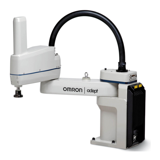
600 eCobra 800 Figure 1-2. eCobra 600 and 800 Models There are two tiers of eCobra robots; the eCobra Pro and the eCobra Standard. The Pro and Standard tiers are physically identical. The Pro models offer faster performance and more fea- tures and connectivity than the Standard models. - Page 14 EtherCAT network cables. The robot interface panel also has switches for setting an expli- cit EtherCAT Node address and operating mode as well as LED's to indicate operating status. Additional Information: Refer to iCS-ECAT Robot Interface Panel on page 24 for more information. eCobra 600 and 800 Robots with EtherCAT 24402-000 Rev B...
- Page 15 8 kHz servo rate to deliver low positional errors and high-performance path following. Digital feed-forward control to maximize efficiency, torque, and positioning. Internal temperature sensors for hardware protection and troubleshooting. 24402-000 Rev B eCobra 600 and 800 Robots with EtherCAT...
-
Page 16: Ip65 And Cleanroom Versions
Yes (only for eCobra 800) Cleanroom option Pass-through, J1 to J2 5 air lines 24 user electrical contacts 1 DeviceNet pass-through Requires XBELTIO Cable for 2nd group of 4 units. Requires XBELTIO Cable. eCobra 600 and 800 Robots with EtherCAT 24402-000 Rev B... -
Page 17: Robot Links And Joints
Chapter 1: Introduction Robot Links and Joints The robot links and joints are described below. Joints 1, 2, and 4 are rotational. Joint 3 is translational. Figure 1-6. Robot Joint Motions - eCobra 600 Robot Shown Meaning Meaning Joint 1 (Shoulder) - Page 18 Internal harnesses are routed through the robot to another set of mating connectors on the top of the outer link as shown below. Additional Information: Refer to Technical Specifications on page 131 for more information. eCobra 600 and 800 Robots with EtherCAT 24402-000 Rev B...
- Page 19 The IO Blox connector on Joint 1 provides an interface to add IO Blox expansion I/O modules to a robot. NOTE: Refer to Connecting Digital I/O to the System on page 67 and the IO Blox User’s Guide (04638-000) for more information. Figure 1-9. IO Blox Connector 24402-000 Rev B eCobra 600 and 800 Robots with EtherCAT...
- Page 20 This 4-pin connector provides the output signals for a second set of optional robot hand valve solenoids or other user-supplied devices. The OP3/4 connector location and pin details are provided below. eCobra 600 and 800 Robots with EtherCAT 24402-000 Rev B...
- Page 21 For example, if you want a break-away gripper to shut down robot high power, this allows you disable high power through a user relay circuit inside the robot. 24402-000 Rev B eCobra 600 and 800 Robots with EtherCAT...
- Page 22 Connector, be careful to not dislodge or remove the encoder connectors nearby. Figure 1-12. End of Arm Break-away Sensor Connector Location Table 1-5. End-effector Break-away Connector Pin Details Pin # Description Pin Location Input +24 VDC Supply eCobra 600 and 800 Robots with EtherCAT 24402-000 Rev B...
- Page 23 See the following table for the pinouts and the following section for the output specifications. Table 1-6. EOAPWR Connector Pinout Pin # Description Pin Location 24 VDC Ground 24 VDC EOAPWR Connector Ground as viewed on robot 24402-000 Rev B eCobra 600 and 800 Robots with EtherCAT...
-
Page 24: Ics-Ecat Robot Interface Panel
Used for connecting the user-supplied 24 VDC power to the robot. A connector is provided with the robot. Refer to Connecting the 24 VDC Cable to the Robot on page 78 for more information. Ground Terminal XSYSTEM Connector eCobra 600 and 800 Robots with EtherCAT 24402-000 Rev B... -
Page 25: Robot Options
Each valve has two output ports: A and B. The output ports are arranged so that when Port A is pressurized, Port B is not pressurized. Conversely, when Port B is pressurized, Port A is not pressurized. 24402-000 Rev B eCobra 600 and 800 Robots with EtherCAT... -
Page 26: End Of Arm Break-Away Sensor
When the circuit is opened, the system will stop with a status code F1 (refer to Status Codes Table on page 171 for more information). Additional Information: Refer to End of Arm Break-away Sensor Connector on page 21 for more information about the connector location. eCobra 600 and 800 Robots with EtherCAT 24402-000 Rev B... -
Page 27: Io Blox
NOTE: This cable is not compatible with the XIO Termination Block described below. XIO Termination Block (part number 90356-40100) Includes terminals for user wiring and I/O status LEDs. Connects to the XIO connector with 2m cable. 24402-000 Rev B eCobra 600 and 800 Robots with EtherCAT... -
Page 28: T20 Pendant
Refer to the following manuals for more information. Automation Control Environment (ACE) Version 4 User's Manual (Cat. No. I633) NJ-series Robot Integrated CPU Unit User's Manual (Cat. No. O037) IPC Application Controller User’s Manual (Cat. No. I632) eCobra 600 and 800 Robots with EtherCAT 24402-000 Rev B... -
Page 29: Front Panel
If you supply your own Front Panel, its design must comply with the require- ments of IEC 60204-1 and ISO 13849. The E-Stop's push button must comply with ISO 13850 (Clause 5.5.2). 24402-000 Rev B eCobra 600 and 800 Robots with EtherCAT... - Page 30 Manual mode, the operator must carry an enabling device such as the T20 pendant. WARNING: PERSONAL INJURY RISK Whenever possible, perform manual mode operations with all per- sonnel outside the workspace. Automatic mode Software programs control the robot allowing operation at full speed. eCobra 600 and 800 Robots with EtherCAT 24402-000 Rev B...
-
Page 31: Camera Bracket Kit
Switches between Manual and Automatic mode (figure shown in Automatic Mode). Camera Bracket Kit The eCobra Robot Camera Bracket Kit (P/N 95000-00100) provides a convenient way of mount- ing cameras to the outer link of the robot. 24402-000 Rev B eCobra 600 and 800 Robots with EtherCAT... -
Page 32: Adjustable Hardstops
Additional Information: Refer to Installing Adjustable Hardstops on page 95 for more information. Table 1-7. Joint 1 Ranges for Adjustable Hardstops Joint and Installation Hardstop Recommended Software Limit Position Value Settings Joint 1, Position 1 ±50° Lower limit: – 49° eCobra 600 and 800 Robots with EtherCAT 24402-000 Rev B... -
Page 33: Optional Cables
This optional adapter cable splits the belt encoder connection on the XBELTIO cable into two belt encoder branches. NOTE: For details on using this cable, refer to XBELT IO Belt Encoder Y Adapter Cable on page 65. 24402-000 Rev B eCobra 600 and 800 Robots with EtherCAT... - Page 34 XIO Breakout Cable Pinout The XIO Breakout cable pinouts are provided below. Table 1-9. XIO Breakout Cable Wire Chart Signal Pin No. Designation Wire Color White 24 VDC White/Black Common 1 Input 1.1 Red/Black eCobra 600 and 800 Robots with EtherCAT 24402-000 Rev B...
- Page 35 Light Blue/Black Output 5 Light Green Output 6 Light Green/Black Output 7 White/Red Output 8 White/Blue Shell Shield Pin 1 Pin 9 Pin 10 Pin 18 Pin 19 Pin 26 24402-000 Rev B eCobra 600 and 800 Robots with EtherCAT...
-
Page 37: Chapter 2: Safety
Chapter 2: Safety This chapter describes the various alert icons used in this manual and their meaning, provides important safety precautions for using OMRON industrial robots and their intended uses, and gives guidance on proper disposal. 2.1 Dangers, Warnings, and Cautions... -
Page 38: Special Information
Never use the robot system for purposes other than described in Intended Use of the Robot on page 40. Contact your local OMRON support if you are not sure of the suit- ability for your application. -
Page 39: What To Do In An Emergency
Limiting Devices There are no dynamic or electro-mechanical limiting devices provided by OMRON Robotics and Safety Technologies, Inc. The robot does not have safety-rated soft axis or space limiting. However, users can install their own safety rated (category 0 or 1) dynamic limiting devices if needed, that comply with ISO 10218-1, Clause 5.12.2. -
Page 40: Intended Use Of The Robot
2.5 Intended Use of the Robot This section lists the intended uses, and prohibitions for use of OMRON industrial robots. DANGER: PERSONAL INJURY RISK This robot is not a collaborative robot. It requires a dedicated work area that prevents personnel from coming into contact with the robot during operation. -
Page 41: Disposal
For information about disposal of your old equipment, contact your local OMRON support. 2.8 How Can I Get Help? Contact your local OMRON Support, or refer to the corporate website: http://www.ia.omron.com 24402-000 Rev B eCobra 600 and 800 Robots with EtherCAT... -
Page 43: Chapter 3: Robot Installation
Table 3-1. Installation Overview 3.2 Mounting an eCobra Robot This section describes the mounting procedure for the eCobra robot. WARNING: PERSONAL INJURY OR PROPERTY DAMAGE RISK Only allow qualified service personnel to install or service the robot. 24402-000 Rev B eCobra 600 and 800 Robots with EtherCAT... -
Page 44: Mounting Surface
Mount eCobra robots on a smooth, flat, level surface that is rigid enough to prevent vibration and flexing during robot operation. OMRON recommends a 25 mm thick steel plate mounted to a rigid tube frame. The following figure shows the mounting hole pattern. - Page 45 8. Verify that the robot's base is squarely mounted (cannot rock back and forth) before inserting and tightening the remaining mounting bolts. 9. Install the user-supplied mounting bolts and washers. Tighten bolts to the torque 24402-000 Rev B eCobra 600 and 800 Robots with EtherCAT...
-
Page 46: Install The Tool Flange
Additional Information: For flange dimensions, hole pattern, and location of flange ground point, refer to Tool Flange Dimensions on page 149. Figure 3-3. Tool Flange eCobra 600 and 800 Robots with EtherCAT 24402-000 Rev B... -
Page 47: Tool Flange Installation Procedure
Connecting the Front Panel You can connect the Front Panel either directly to the XFP connector on the XSYSTEM cable (A), or to the Front Panel cable (B). 24402-000 Rev B eCobra 600 and 800 Robots with EtherCAT... -
Page 48: Front Panel Schematic
If you supply your own Front Panel E-Stop, its design must comply with the requirements of IEC 60204-1 and ISO 13849. The E-Stop's push button must comply with ISO 13850. eCobra 600 and 800 Robots with EtherCAT 24402-000 Rev B... -
Page 49: Installing User-Supplied Safety Equipment
D-sub connectors. Refer to the following sections for safety equipment connection details. Contacts on XUSR Connector Use the information in the following table to understand the signals provided on the XUSR connector. 24402-000 Rev B eCobra 600 and 800 Robots with EtherCAT... - Page 50 Manual or Automatic indication Contacts are closed in Automatic mode CH 1 10, 23 Manual or Automatic indication Contacts are closed in Automatic mode CH 2 11, 12, No connection 13, 24, eCobra 600 and 800 Robots with EtherCAT 24402-000 Rev B...
-
Page 51: Contacts On Xfp Connector
Do not inadvertently connect 24 VDC signals to these pins as that will damage the elec- tronics. NOTE: Underwriters Laboratory evaluated the system with an OMRON Front Panel. Using a substitute front panel could void UL compliance. Remote Pendant Signals on the XMCP Connector Use the information in the following table to understand the remote pendant signals provided on the XMCP connector. - Page 52 No connection No connection Shield Shield GND 24 VDC No connection The preceding table gives descriptions of this circuit's functionality. The following figure shows an E-Stop diagram for the system. eCobra 600 and 800 Robots with EtherCAT 24402-000 Rev B...
-
Page 53: E-Stop Circuits On Xusr And Xfp Connectors
XSYSTEM-30 XSYSTEM-27 (XUSR-22) (XUSR-5) (XUSR-6) XSYSTEM-8 XSYSTEM-38 (XPND-26) (XPND-25) XSYSTEM-29 (XUSR-18) XSYSTEM-44 (XUSR-19) XSYSTEM-26 (XUSR-8) XSYSTEM-10 (XUSR-7) XSYSTEM-25 (XUSR-20) XSYSTEM-40 (XUSR-21) Figure 3-7. E-Stop Circuit on XUSR and XFP Connectors 24402-000 Rev B eCobra 600 and 800 Robots with EtherCAT... -
Page 54: Emergency Stop Circuits
User E-Stop contacts, so they will not indicate the status of the Line E-Stop, MCP ENABLE, or the Muted Safety gate. If you have a specific need for this function, contact your local OMRON support for information on alternate indicating modes. - Page 55 If you want the cell gate to always cause a robot shutdown, wire the gate switch contacts in series with the user E-Stop inputs. Do not wire the gate switch into the muted safety gate inputs. 24402-000 Rev B eCobra 600 and 800 Robots with EtherCAT...
-
Page 56: Remote Manual Mode
There are two methods to provide high power ON / OFF control in a remote location as described below. DANGER: A High Power push-button must be installed outside of the robot's workspace. eCobra 600 and 800 Robots with EtherCAT 24402-000 Rev B... -
Page 57: Using A User-Supplied Control Panel
You can create a user-supplied control panel that performs the same functions as the optional Front Panel. The optional Front Panel contains only switches and lights (no active com- ponents). Additional Information: Refer to Front Panel Schematic on page 48 for internal wiring information. 24402-000 Rev B eCobra 600 and 800 Robots with EtherCAT... -
Page 58: Remote Pendant Usage
IMPORTANT: Underwriters Laboratory evaluated the system with an OMRON Front Panel. If you provide a substitute, the system may no longer be UL com- pliant. IMPORTANT: Though the XMCP and XFP connectors can be interchanged without electrical damage, neither the Front Panel nor the pendant will work properly unless they are plugged into the correct connector. -
Page 59: Setting The Ethercat Node Id Using Hardware Switches
ID (address) as described in the figure below. The switch settings are checked when robot 24 VDC power is applied. IMPORTANT: Turn OFF AC and DC power before changing EtherCAT node ID switches. Figure 3-9. Robot Interface Panel EtherCAT ID Switches 24402-000 Rev B eCobra 600 and 800 Robots with EtherCAT... - Page 60 NOTE: Use Sysmac Studio to verify the EtherCAT node ID setting. Refer to Sys- mac Studio Version 1 Operation Manual (Cat. No. W504) for more information. Figure 3-10. EtherCAT Node ID Set to 196 eCobra 600 and 800 Robots with EtherCAT 24402-000 Rev B...
-
Page 61: Chapter 4: System Cable Installation
NOTE: The figure below includes the optional and user-supplied equipment that may not be present in your system. Additional Information: Ethernet / EtherCAT network connections may differ for your application. Contact your local OMRON support for more information. 24402-000 Rev B eCobra 600 and 800 Robots with EtherCAT... -
Page 62: List Of Cables And Parts
Figure 4-1. Typical System Cable Connections List of Cables and Parts The following table identifies and provides details about cables and parts illustrated in Basic System Cable Layout on page 61. eCobra 600 and 800 Robots with EtherCAT 24402-000 Rev B... - Page 63 200-240 VAC AC Power Cable 04118-000 24 VDC Power Cable 04120-000 Cable Assembly, XSYSTEM 13322-100 Adapter with Jumpers XFP Connector on XSYSTEM cable XFP Jumper Plug 10052-000 Front Panel 90356-10358 24402-000 Rev B eCobra 600 and 800 Robots with EtherCAT...
-
Page 64: Cable Installation Steps
Connect T20 adapter cable (not shown) to XSYSTEM cable XMCP con- nector. If no T20 is present in the system, install XMCP jumper, or T20 Adapter Cable with bypass plug. eCobra 600 and 800 Robots with EtherCAT 24402-000 Rev B... -
Page 65: Xbelt Io Belt Encoder Y Adapter Cable
E, F, G, H, J, K, Additional Information: Ethernet / EtherCAT network con- nections may differ. Contact your local OMRON support for more information. XBELT IO Belt Encoder Y Adapter Cable The XBELT IO Encoder Y Adapter Cable adds two additional encoder outputs (for ENC1 and ENC2, to the Belt Branch. - Page 66 Item letters in XBELT IO Belt Encoder Y Adapter Cable on page 65. Belt Encoder Figure 4-3. XBELT I/O Adapter Cable Pinout - Encoder 1 and 2 Connections RS-232 eCobra 600 and 800 Robots with EtherCAT 24402-000 Rev B...
-
Page 67: Connecting Digital I/O To The System
Refer to the IO Blox User’s connects to the RS232 up to 4 IO Blox devices for the Guide (04638-000) connector on the back of Standard eCobra, up to 8 IO Blox 24402-000 Rev B eCobra 600 and 800 Robots with EtherCAT... -
Page 68: Digital I/O Signal Configuration
IO Blox units with duplicate addresses will conflict. Refer to the IO Blox User’s Guide (04638-000) for more information. Figure 4-7. Connecting IO Blox to the system (maximum of 4 for Standard, 8 for Pro) eCobra 600 and 800 Robots with EtherCAT 24402-000 Rev B... - Page 69 The XIO Termination Block provides 12 inputs and 8 outputs (refer to the following figure). This offers the same signal capacity as the XIO connector on the robot interface panel. Figure 4-8. Connecting XIO Termination Block 24402-000 Rev B eCobra 600 and 800 Robots with EtherCAT...
- Page 70 ON, OFF Inputs on IOBlox 1073 to 1080 OFF, ON Inputs on IOBlox 1081 to 1088 ON, ON Inputs on IOBlox 1089 to 1096 Inputs on the 1097 to iCS-ECAT 1108 eCobra 600 and 800 Robots with EtherCAT 24402-000 Rev B...
- Page 71 1281 to 1288 Inputs on the 1289 to iCS-ECAT 1300 EXPIO IOBlox OFF, OFF Inputs on IOBlox 1321 to Group 1 1328 ON, OFF Inputs on IOBlox 1329 to 1336 24402-000 Rev B eCobra 600 and 800 Robots with EtherCAT...
- Page 72 Inputs on IOBlox 1513 to Group 1 1520 ON, OFF Inputs on IOBlox 1521 to 1528 OFF, ON Inputs on IOBlox 1529 to 1536 ON, ON Inputs on IOBlox 1537 to 1544 eCobra 600 and 800 Robots with EtherCAT 24402-000 Rev B...
- Page 73 1721 to 1728 ON, ON Inputs on IOBlox 1729 to 1736 XBELTIO IOBlox OFF, OFF Inputs on IOBlox 1737 to Group 2 1744 ON, OFF Inputs on IOBlox 1745 to 1752 24402-000 Rev B eCobra 600 and 800 Robots with EtherCAT...
- Page 74 Outputs on IOBlox 6 169 to 176 OFF, ON Outputs on IOBlox 7 177 to 184 ON, ON Outputs on IOBlox 8 185 to 192 Outputs on the iCS- 193 to 200 ECAT eCobra 600 and 800 Robots with EtherCAT 24402-000 Rev B...
- Page 75 Outputs on IOBlox 6 457 to 464 OFF, ON Outputs on IOBlox 7 465 to 472 ON, ON Outputs on IOBlox 8 473 to 480 Outputs on the iCS- 481 to 488 ECAT 24402-000 Rev B eCobra 600 and 800 Robots with EtherCAT...
-
Page 76: Xio Connector Signals
The XIO connector on the robot interface panel offers access to digital I/O (12 inputs and 8 out- puts). Refer to the following table for the XIO signal designations. 12 Inputs, signals 1097 to 1108 8 Outputs, signals 0097 to 0104 eCobra 600 and 800 Robots with EtherCAT 24402-000 Rev B... - Page 77 Output 3 0099 Output 4 0100 Output 5 0101 Output 6 0102 Output 7 0103 Output 8 0104 Pin 9 Pin 1 Pin 18 Pin 10 Pin 26 Pin 19 24402-000 Rev B eCobra 600 and 800 Robots with EtherCAT...
-
Page 78: Connecting The 24 Vdc Cable To The Robot
Power requirements for the user-supplied power supply vary depending on the configuration of the robot and connected devices. OMRON recommends a 24 VDC, 6 A power supply to allow for startup current draw from connected user devices, such as solenoids and digital I/O loads. -
Page 79: Making The 24 Vdc Power Supply Cable
The following instructions correspond to the numbered steps in green boxes in the following figure. The red circled letters identify specific items. 24402-000 Rev B eCobra 600 and 800 Robots with EtherCAT... - Page 80 The 24 VDC output must be less than 300 W peak or 8 Amp (max) in- line circuit protection must be provided for each connected robot. Refer to (D) in Figure 4-10. . eCobra 600 and 800 Robots with EtherCAT 24402-000 Rev B...
-
Page 81: Connecting 200-240 Vac Power Cable
NOTE: Install the robot system as a piece of equipment in a permanently- installed system. AC Power Diagrams If using a three-phase power source, it must be symmetrically-earthed (with grounded neutral). Connections called out as single-phase can be wired Line-to-Neutral or Line-to-Line. 24402-000 Rev B eCobra 600 and 800 Robots with EtherCAT... - Page 82 User-supplied AC power cable F1 - 10A NOTE: F1 is user-supplied, and must be slow-blow L=Line N=Neutral E=Earth Ground Figure 4-12. Single-Phase Load across L1 and L2 of a Three-Phase Supply eCobra 600 and 800 Robots with EtherCAT 24402-000 Rev B...
-
Page 83: Ac Power Supply Connector
7. Tighten the screws on the cable clamp, then reinstall the cover and tighten the screw. 8. Prepare the opposite end of the cable for connection to the facility AC power source. 24402-000 Rev B eCobra 600 and 800 Robots with EtherCAT... -
Page 84: Connecting The Ac Power Supply Cable
3. Secure the AC connector with the locking latch. 4.5 Grounding the Robot System Proper grounding is essential for safe and reliable robot operation. Follow these recom- mendations to properly ground your robot. eCobra 600 and 800 Robots with EtherCAT 24402-000 Rev B... -
Page 85: Grounding The Robot Base
DANGER: ELECTROCUTION HAZARD Failing to ground robot-mounted equipment or tooling that uses hazardous voltages could lead to injury or fatality of a person touching the end-effector during an electrical fault. 24402-000 Rev B eCobra 600 and 800 Robots with EtherCAT... -
Page 87: Chapter 5: Optional Equipment Installation
Refer to Grounding Robot-Mounted Equipment on page 85 for more information. 24402-000 Rev B eCobra 600 and 800 Robots with EtherCAT... -
Page 88: Mounting Locations For External Equipment
A second external equipment mounting location is on the top side of the outer link as shown in the figure below. Figure 5-3. External Tooling Location, Outer Link (top) A third external equipment mounting location is on the bottom side of the outer link. eCobra 600 and 800 Robots with EtherCAT 24402-000 Rev B... -
Page 89: Installing The Solenoid Valve Kit
Solenoid Option Consideration for Cleanroom Robots on page 168 for more information. Before beginning this procedure, have the following items available. Hex drives Cable ties Diagonal wire cutters Solenoid Valve Kit Figure 5-5. Solenoid Valve Kit Assembly Installed 24402-000 Rev B eCobra 600 and 800 Robots with EtherCAT... -
Page 90: Solenoid Valve Kit Installation Procedure
1. Turn OFF all power to the robot. 2. Remove the screws from each side of the outer link cover (two screws on an eCobra 600, three screws on an 800). Remove two screws on top and remove the cover. Retain the screws for reassembly. - Page 91 9. Install the appropriate lengths of approximately 4 inch plastic tubing (supplied) into the two output ports on the manifold. 10. Route the tubing up along the tower bracket next to the quill and down through the 24402-000 Rev B eCobra 600 and 800 Robots with EtherCAT...
- Page 92 Figure 5-9. Removing the Cable Strap Plate showing two M5x8 screws (A) and the cable strap plate (B) 13. Remove the four screws from the Joint 1 cover. Retain the screws for re-assembly. Figure 5-10. Joint 1 Cover Screws (circled) eCobra 600 and 800 Robots with EtherCAT 24402-000 Rev B...
-
Page 93: Testing Solenoid Valve Kit Installation
Use the following procedure to install the Camera Bracket Kit. 1. Install the camera plate to the outer link with four M5 x 12 mm screws using the mount- ing holes shown in the figure below. 24402-000 Rev B eCobra 600 and 800 Robots with EtherCAT... - Page 94 5. Mount the camera and camera mount to the camera channel using M5 x 12 mm screws. Figure 5-12. Mounting a Camera Plate (A), Camera Brackets (B), Camera Channel (C), and Camera Mount (D) on the Robot. eCobra 600 and 800 Robots with EtherCAT 24402-000 Rev B...
-
Page 95: Installing Adjustable Hardstops
Refer to the Sysmac Studio Version 1 Operation Manual (Cat. No. W504) for more information. Refer to Adjustable Hardstops on page 32 for information about robot joint range limitations. 24402-000 Rev B eCobra 600 and 800 Robots with EtherCAT... -
Page 96: Joint 2 Adjustable Hardstop Installation
1. Slide the two adjustable hardstop plates into the space between inner and outer links (see Figure 5-15. Looking up at the inner link from underneath, align the holes in the plates with the holes in the inner link(see Figure 5-16. eCobra 600 and 800 Robots with EtherCAT 24402-000 Rev B... - Page 97 Figure 5-16. Screw Locations for Joint 2 Adjustable Hardstops (as seen from below) Item Meaning Item Meaning Joint 2 Left Hardstop Joint 2 Negative direction Plate installed in +81° position Joint 2 Right Hardstop Joint 2 Positive direction 24402-000 Rev B eCobra 600 and 800 Robots with EtherCAT...
- Page 98 Refer to the Sysmac Studio Version 1 Operation Manual (Cat. No. W504) for more information. Refer to Adjustable Hardstops on page 32 for information about robot joint range limitations. eCobra 600 and 800 Robots with EtherCAT 24402-000 Rev B...
-
Page 99: Chapter 6: System Operation
If a pendant is present, ensure it is connected to the XMCP on the XSYSTEM cable. If not using a pendant, ensure the appropriate jumper is installed. Ensure the XSYSTEM cable is connected to the XSYSTEM connector on the robot inter- face panel. 24402-000 Rev B eCobra 600 and 800 Robots with EtherCAT... -
Page 100: User-Supplied Safety Equipment Checks
If E-Stop or Teach Restrict configuration is necessary, the supplied jumper plug (11901- 000) must be installed on the XBELLTIO connector on the robot interface panel. Figure 6-1. Safety Equipment Check Jumper Plug eCobra 600 and 800 Robots with EtherCAT 24402-000 Rev B... -
Page 101: Switch Position Checks
Robot boot in progress. Refer to Status Codes on page 171 for more information. ON Flashing (5 Hz) Status Code(s) System fault is present. Refer to Status Codes on page 171 for more information. 24402-000 Rev B eCobra 600 and 800 Robots with EtherCAT... -
Page 102: Ethercat Communications Description
There is an unrecoverable error, such as a hardware error or an exception. Flashing There is a recoverable error. Not lit There is no error. Yellow Not Lit Reserved for Future Use eCobra 600 and 800 Robots with EtherCAT 24402-000 Rev B... -
Page 103: System Behavior With Ethercat Communication Errors
Joint 3 is supported while releasing the brake, and verify that the end-effector or other installed tooling is clear of all obstructions. IMPORTANT: Pressing the brake release button while high power is ON auto- matically turns high power OFF. 24402-000 Rev B eCobra 600 and 800 Robots with EtherCAT... -
Page 104: Remote Brake Release Feature
). In this mode, the robot will respond to the control signals coming from the pendant. NOTE: Controlling the robot from a single location satisfies the single point of control requirement from ISO-10218-1. eCobra 600 and 800 Robots with EtherCAT 24402-000 Rev B... -
Page 105: Automatic Mode
NJ-series Robot Integrated CPU Unit. IMPORTANT: The operating mode switch state is checked only during robot startup after power is applied. If the following conditions are present on your system, contact your local OMRON rep- resentative for support. 24402-000 Rev B... -
Page 106: Manually Jogging The Robot
Additional Information: If a Front Panel is not present, the high power lamp and high power button signals can be accessed with the XFP system cable con- nector. Refer to Front Panel Schematic on page 48 for more information. eCobra 600 and 800 Robots with EtherCAT 24402-000 Rev B... -
Page 107: High Power And Faults
Request High Power with the Pendant The handheld pendant can be used to request high power to the robot. Refer to the T20 Pendant User's Manual (Cat. No. I601) for more information. 24402-000 Rev B eCobra 600 and 800 Robots with EtherCAT... -
Page 108: Disabling Robot High Power
The conditions described below can disable or prevent the robot high power state. Robot faults - refer to High Power and Faults on page 107 for more information. E-stop open circuit detection. eCobra 600 and 800 Robots with EtherCAT 24402-000 Rev B... - Page 109 Chapter 6: System Operation User programming with the POWER system switch keyword. External signal state control through the XUSR connector on the XSYSTEM cable. 24402-000 Rev B eCobra 600 and 800 Robots with EtherCAT...
-
Page 111: Chapter 7: Maintenance
Use the following steps to check all robot safety devices that may be present in the system. These tests should be done every six months. IMPORTANT: Operating any of the following safety devices should disable robot high power. 24402-000 Rev B eCobra 600 and 800 Robots with EtherCAT... -
Page 112: Checking Robot Mounting Bolts And Cover Plates
The part number of this label is 18241-000. Figure 7-1. Read Manual and Impact Warning Label This is placed in the following location on the robot. eCobra 600 and 800 Robots with EtherCAT 24402-000 Rev B... - Page 113 18272-000. Figure 7-3. Brake Release/Gravity Label Lifting Point Label This label is partially around the eyebolt, marking that as a point to lift from. The part number is 08613-000. 24402-000 Rev B eCobra 600 and 800 Robots with EtherCAT...
-
Page 114: Checking For Oil Leaks
The eCobra robots use oil in the gearboxes for lubrication. Periodically inspect the robot for any signs of oil in areas immediately outside of the gearboxes. Check the locations identified in the following image. Figure 7-5. eCobra Oil Leak Inspection Areas eCobra 600 and 800 Robots with EtherCAT 24402-000 Rev B... -
Page 115: Lubricating Joint 3
4. Press the 'Z' BRAKE RELEASE button (above the 2-digit Robot Status Display) and move Joint 3 to the top of its travel. Remove any existing grease with a clean, lint-free, soft cloth. 24402-000 Rev B eCobra 600 and 800 Robots with EtherCAT... - Page 116 8. Move Joint 3 up and down several times to spread the grease evenly. 9. Remove 24 VDC power from the robot. 10. Reinstall the outer link cover. IMPORTANT: For Cleanroom and IP65 versions, reinstall or replace the bellows. eCobra 600 and 800 Robots with EtherCAT 24402-000 Rev B...
-
Page 117: Replacing The Encoder Battery Pack
Every 2 to 4 years, or if the robot's 2-digit Status Display shows the battery low BA ( ) error, you must replace the battery pack to keep from losing encoder data (which renders the robot 24402-000 Rev B eCobra 600 and 800 Robots with EtherCAT... - Page 118 5. While holding the chassis heat sink, carefully and slowly lower the chassis down. This provides access to the battery pack, as shown in the following figure. eCobra 600 and 800 Robots with EtherCAT 24402-000 Rev B...
-
Page 119: Non-Periodic Maintenance
13. Reconnect the 24 VDC supply cable to the robot +24 VDC input connector. 7.2 Non-Periodic Maintenance This section provides information and instructions for performing maintenance that does not occur at regular intervals. 24402-000 Rev B eCobra 600 and 800 Robots with EtherCAT... -
Page 120: Field-Replaceable Parts
If you remove the flange, you must reinstall it in exactly the same position to avoid losing the calibration for the robot. The setscrew on the flange holds the rotational position of the flange on the quill shaft (refer to the following figure). eCobra 600 and 800 Robots with EtherCAT 24402-000 Rev B... -
Page 121: Replacing The Ics-Ecat Amplifier Chassis
This section describes the process of removing and replacing the iCS-ECAT amplifier. IMPORTANT: The Teach Restrict and E-stop hardware delay configurations are lost when replacing an iCS-ECAT unit. These safety settings must be configured 24402-000 Rev B eCobra 600 and 800 Robots with EtherCAT... - Page 122 The chassis can be laid flat or placed to the right side of the robot for better access. eCobra 600 and 800 Robots with EtherCAT 24402-000 Rev B...
- Page 123 125 for more information. 6. Disconnect the amplifier cable from the white amplifier connector located on the chassis bracket (callout (A) in the following figure). Figure 7-11. Connectors on Chassis and ePMAI Board 24402-000 Rev B eCobra 600 and 800 Robots with EtherCAT...
- Page 124 1. Carefully remove the new chassis from its packaging, check it for any signs of damage, and remove any foreign packing materials or debris from inside the chassis. 2. Carefully place the chassis next to the robot. eCobra 600 and 800 Robots with EtherCAT 24402-000 Rev B...
-
Page 125: Remove And Replace A Microsd Card
Refer to Removing the iCS-ECAT Amplifier Chassis on page 122. 3. Lay the chassis on its back next to the robot so you can access the connector end of the iCS-ECAT. 24402-000 Rev B eCobra 600 and 800 Robots with EtherCAT... -
Page 126: Change Front Panel High-Power On Lamp
The access covers on the Front Panel are not interlocked – turn off and disconnect power before removing the cover. 1. Remove all power from the robot. 2. Disconnect the cable between the Front Panel and the iCS-ECAT. eCobra 600 and 800 Robots with EtherCAT 24402-000 Rev B... - Page 127 6. Locate the lamp body in the center of the back side of the front cover. Turn the lamp body approximately 20° in either direction and then pull straight back. 24402-000 Rev B eCobra 600 and 800 Robots with EtherCAT...
- Page 128 The lamp body is now free, and you can remove the old lamp. Figure 7-17. High Power Lamp Removed 7. Re-install the lamp body by pushing it straight into the lamp housing receptacle. Ensure the proper orientation of lamp body contacts. eCobra 600 and 800 Robots with EtherCAT 24402-000 Rev B...
- Page 129 1. Re-install the two screws on the back of the body. 2. Re-install the Front Panel in its mounting. 3. Reconnect the cable between the Front Panel and the iCS-ECAT. 24402-000 Rev B eCobra 600 and 800 Robots with EtherCAT...
-
Page 131: Chapter 8: Technical Specifications
This section provides physical dimensions for the eCobra 600 and 800 robots and their oper- ating envelope. Figure 8-1. eCobra 600 robot Top and Side Dimensions (units in mm) where (A) is the (required clear- ance to open iCS-ECAT chassis, and (B) is the required cable clearance of 31 mm... - Page 132 Figure 8-2. eCobra 800 robot Top and Side Dimensions (units in mm) where (A) is the (required clear- ance to open iCS-ECAT chassis, and (B) is the required cable clearance of 31 mm eCobra 600 and 800 Robots with EtherCAT 24402-000 Rev B...
- Page 133 Chapter 8: Technical Specifications 2X M4x0.7-6H +.10 -.03 2X M4x0.7-6H Figure 8-3. (A) Dimensions of the Camera Bracket Mounting Pattern (units in mm) (457 mm to base) for eCobra 600 and 800 24402-000 Rev B eCobra 600 and 800 Robots with EtherCAT...
- Page 134 Figure 8-4. External Tooling on Top of Robot Arm, Inner link (top), outer link (bottom), eCobra (units in mm) 76 - eCobra 600 135 - eCobra 800 4X M4x0.7-6H Figure 8-5. External Tooling on Underside of Outer Link (bottom) (units in mm) eCobra 600 and 800 Robots with EtherCAT 24402-000 Rev B...
- Page 135 Chapter 8: Technical Specifications 105° 105° 150° 150° Figure 8-6. eCobra 600 Robot Working Envelope Meaning Meaning Maximum intrusion contact Minimum radial reach 162.6mm radius 647mm Maximum radial reach func- Cartesian limits 300mm tional area 600mm 24402-000 Rev B eCobra 600 and 800 Robots with EtherCAT...
-
Page 136: General Robot Specifications
The following table provides general robot specifications. Table 8-1. General Robot Specifications Item eCobra 600 Robot eCobra 800 Robot Specification Specification Reach 600 mm 800 mm Payload—rated 2.0 kg 2.0 kg eCobra 600 and 800 Robots with EtherCAT 24402-000 Rev B... -
Page 137: Performance Specifications
The Adept Cycle is defined as a continuous path with straight-line motion cycle in which the robot tool moves up 25 mm, over 305 mm, down 25 mm, and then back along the same 24402-000 Rev B eCobra 600 and 800 Robots with EtherCAT... -
Page 138: Stopping Distances And Times
NOTE: Where lines overlap (and may not be visible) differences are not sig- nificant. eCobra 600 J1 Stopping Distance (Cobra600) Payload 33% Payload 66% Payload 100% Speed (%) Figure 8-8. Stopping Distance in Degrees versus Speed % for eCobra 600, Joint 1 eCobra 600 and 800 Robots with EtherCAT 24402-000 Rev B... - Page 139 Figure 8-9. Stopping Time in Seconds versus Speed% for eCobra 600, Joint 1 J2 Stopping Distance (Cobra600) Payload 33% Payload 66% Payload 100% Speed (%) Figure 8-10. Stopping Distance in Degrees versus Speed % for eCobra 600, Joint 2 24402-000 Rev B eCobra 600 and 800 Robots with EtherCAT...
- Page 140 J2 Stopping Time (Cobra600) Payload 33% Payload 66% Payload 100% Speed (%) Figure 8-11. Stopping Time in seconds versus Speed % for eCobra 600, Joint 2 J3 Stopping Distance (Cobra600) Payload 33% Payload 66% Payload 100% Speed (%) Figure 8-12. Stopping Distance (mm) versus Speed (%) for eCobra 600, Joint 3...
- Page 141 Chapter 8: Technical Specifications J3 Stopping Time (Cobra600) Payload 33% Payload 66% Payload 100% Speed (%) Figure 8-13. Stopping Time in Seconds versus Speed (%) for eCobra 600, Joint 3 eCobra 800 J1 Stopping Distance (Cobra800) Payload 33% Payload 66% Payload 100% Speed (%) Figure 8-14.
- Page 142 Figure 8-15. Stopping Time in Seconds versus Speed (%) for eCobra 800, Joint 1 J2 Stopping Distance (Cobra800) Payload, 33,% Payload, 66,% Payload, 100,% Speed (%) Figure 8-16. Stopping Distance in Degrees versus Speed (%) for eCobra 800, Joint 2 eCobra 600 and 800 Robots with EtherCAT 24402-000 Rev B...
- Page 143 Figure 8-17. Stopping Time in Seconds versus Speed (%) for eCobra 800, Joint 2 J3 Stopping Distance (Cobra800) Payload 33% Payload 66% Payload 100% Speed (%) Figure 8-18. Stopping Distance in Millimeters versus Speed (%) for eCobra 800, Joint 3 24402-000 Rev B eCobra 600 and 800 Robots with EtherCAT...
-
Page 144: Hardstop And Softstop Limits
If you want to measure stopping distances and time in a real cell with a real robot and with real tools and loads, contact your local OMRON support. Hardstop and Softstop Limits Use the table below to understand the robot hardstop and softstop limits. -
Page 145: Electrical Specifications
Output must be less than 300 W peak or provide 8 Amp in-line circuit protection Cabling 1.31 – 2.08 mm² (16-14 AWG) Shielding Braided shield connected to frame ground terminal at both ends of cable. 24402-000 Rev B eCobra 600 and 800 Robots with EtherCAT... - Page 146 1.5 A @ 25°C Maximum ON state res- 0.32 Ω @ 85°C istance (I = 0.5 A) Maximum output leakage 25 μA current ON response time 125 μsec max., 80 μsec typical (hardware eCobra 600 and 800 Robots with EtherCAT 24402-000 Rev B...
-
Page 147: Environment And Facility Specifications
The robot installation must meet the following operating environment specifications. Table 8-6. Robot System Operating Environment Requirements Item Specification Ambient operating temperature 5 to 40°C 5 to 35°C (cleanroom models) 24402-000 Rev B eCobra 600 and 800 Robots with EtherCAT... -
Page 148: Other Specifications
Compressed Air Fitting (Cleanroom option 6 mm diameter only) Pressure: 0.3 MPa + 10% Flow: 0.06 m /min Pneumatic pass-through ports 6 mm diameter (quantity 2) 4 mm diameter (quantity 3) eCobra 600 and 800 Robots with EtherCAT 24402-000 Rev B... -
Page 149: Power Consumption Specifications
For short durations (100 ms). For details on Adept cycle, see General Performance Information on page 137. 8.7 Tool Flange Dimensions The following figure provides dimensions for the tool flange. 24402-000 Rev B eCobra 600 and 800 Robots with EtherCAT... -
Page 150: Front Panel Dimensions
Flange edge - see callout (D) for Tool Flange Ground profile and dimensions Dowel pin hole Flange rim dimensions from callout (A) 8.8 Front Panel Dimensions The following figures provide Front Panel enclosure dimensions. eCobra 600 and 800 Robots with EtherCAT 24402-000 Rev B... -
Page 151: Ethercat Communications Specifications
NOTE: Design of the factory-supplied Front Panel E-Stop is in accordance with the requirements of IEC 60204-1 and ISO 13849 8.9 EtherCAT Communications Specifications EtherCAT communications specifications are provided in the table below. Figure 8-23. EtherCAT Communications Specification Description 24402-000 Rev B eCobra 600 and 800 Robots with EtherCAT... - Page 152 Recommended cable: straight, double-shielded cable with aluminum tape and braiding Maximum transmission distance 100 m between nodes Communications cycle 2 ms, 4 ms Wiring in a ring configuration is not possible. eCobra 600 and 800 Robots with EtherCAT 24402-000 Rev B...
-
Page 153: Chapter 9: Ip65 Option Considerations
The IP65 robot provides the hardware needed to achieve an IP65 protection level, but you must provide a way of sealing the tool flange and pressurizing the robot through the com- pressed air attachment fitting (located at the top of the robot). 24402-000 Rev B eCobra 600 and 800 Robots with EtherCAT... -
Page 154: Sealing The Tool Flange
41.15 76.2 Figure 9-2. eCobra 800 IP65 Tool Flange (units in mm) Pressurizing the Robot You must supply compressed air to keep a positive airflow pressure in the robot cavity. eCobra 600 and 800 Robots with EtherCAT 24402-000 Rev B... - Page 155 Failure to do this could result in moisture or particle buildup inside the robot, lead to reduced performance or damage to the robot, and could void your warranty. 24402-000 Rev B eCobra 600 and 800 Robots with EtherCAT...
-
Page 156: Cable Seal Assembly
Part number 04817-000 Cable Seal Flange (lower) Part number 04815-000 NOTE: Shown with Cable Seal (P/N 04818-000) in place. Installation Procedure Use the following procedure to install the cable seal assembly. eCobra 600 and 800 Robots with EtherCAT 24402-000 Rev B... - Page 157 M6 flat washers. Make sure that none of the cable are pinched or crimped when installing the upper flange. 7. Attach the flange assembly using one M6 x 20 screw, one M6 lock washer, and one M6 flat washer. See Figure 9-7. 24402-000 Rev B eCobra 600 and 800 Robots with EtherCAT...
-
Page 158: Dimension Drawing For Cable Seal Assembly
8. Install the splash guard using two M6 x 20 screws, two M6 lock washers, and two M6 flat washers. See Figure 9-8. Dimension Drawing for Cable Seal Assembly The following diagram provides dimensional details of the cable seal assembly. eCobra 600 and 800 Robots with EtherCAT 24402-000 Rev B... -
Page 159: Remove And Reinstall Outer Link Cover
CAUTION: PROPERTY DAMAGE RISK Do not loosen these screws any more than two turns, as the special clamp nut on the inside of the cover might come loose and fall inside the robot. 24402-000 Rev B eCobra 600 and 800 Robots with EtherCAT... -
Page 160: Outer Link Cover Reinstallation Procedure
(refer to the following figure). Figure 9-11. IP65 Robot with Outer Link Cover Removed Outer Link Cover Reinstallation Procedure Use the following procedure to reinstall the outer link cover. eCobra 600 and 800 Robots with EtherCAT 24402-000 Rev B... - Page 161 We recommend this pattern to achieve a bal- anced secure fit around the cover. 8. Reinstall the collar nut and tighten until secure. 9. Turn on the compressed air supply to the system before restarting the robot. 24402-000 Rev B eCobra 600 and 800 Robots with EtherCAT...
-
Page 162: Ip65 Robot Connections
IO Blox 6 mm Air Lines (2x) The user electrical connectors on the outer link are accessible with the cover removed. See the following figure for locations of the internal connectors. eCobra 600 and 800 Robots with EtherCAT 24402-000 Rev B... -
Page 163: Pneumatic Pass-Through Connections
The internal air line normally used to supply the solenoid manifold is instead used to provide positive airflow pressure to the bellows / outer link. You can use one of the passive 6 mm user air lines shown in Figure 9-12. and Figure 9-13. 24402-000 Rev B eCobra 600 and 800 Robots with EtherCAT... -
Page 164: Ip65 Option Maintenance
Align the mating surfaces of the clamp half-rings with the bellows seam—see Tighten the screw to secure the clamp. NOTE: Align the bellows clamps with the bellows seam, on both upper and lower clamps Figure 9-14. Bellows Replacement and Alignment eCobra 600 and 800 Robots with EtherCAT 24402-000 Rev B... - Page 165 Chapter 9: IP65 Option Considerations Meaning Meaning Upper Bellows Clamp Bellows Seam Bellows Bellows Clamp Lower Bellows Clamp Bellows Bellows Clamp 24402-000 Rev B eCobra 600 and 800 Robots with EtherCAT...
-
Page 167: Chapter 10: Cleanroom Option Considerations
IMPORTANT: You must use an additional high flow rate vacuum source to evacuate the inner link and base. An eCobra 600 with the Cleanroom option is shown in the figure below. Figure 10-1. eCobra 600 - Cleanroom Option 10.2 User Requirements to Meet Cleanroom Rating The following table lists the vacuum and compressed air source requirements to meet the Cleanroom rating. -
Page 168: Cleanroom Robot Connections
Port - 3/4 inch NPT Female Fitting (B) Robot Solenoid Option Consideration for Cleanroom Robots If you are installing the internally mounted solenoid valves on a robot with the Cleanroom option, the following considerations must be made. eCobra 600 and 800 Robots with EtherCAT 24402-000 Rev B... -
Page 169: Cleanroom Option Maintenance
4. Remove the upper bellows clamp ring by loosening the screw on the clamp. 5. Slide the old bellows down off of the quill. 6. Install a new bellows, and reverse the steps listed above. 24402-000 Rev B eCobra 600 and 800 Robots with EtherCAT... - Page 170 Figure 10-3. Cleanroom Bellows Replacement Meaning Upper Bellows Clamp Ring Bellows Lower Bellows Clamp Ring User Tool Flange eCobra 600 and 800 Robots with EtherCAT 24402-000 Rev B...
- Page 171 24 VDC power supply. *Motor Amplifier -1018 A power amplifier fault is Check user motor Fault* indicated on axis #. power connections for shorts or opens. 24402-000 Rev B eCobra 600 and 800 Robots with EtherCAT...
- Page 172 Help. fault. *E-STOP detected -643 An E-STOP condition has This is a normal by robot* been detected by the response to many robot. E-STOP conditions. Remove the source eCobra 600 and 800 Robots with EtherCAT 24402-000 Rev B...
- Page 173 (I0, I1, sists longer than 30 …) on the display during seconds. Could indic- normal system boot. ate servo ini- tialization failure. Contact your local OMRON support. 24402-000 Rev B eCobra 600 and 800 Robots with EtherCAT...
- Page 174 *Safety System -1109* Robot hardware did not Contact your local Fault* Code 0 detect pressing the Front OMRON support. Panel high-power button before the servo system attempted to enable power. eCobra 600 and 800 Robots with EtherCAT 24402-000 Rev B...
- Page 175 E-Stop missioned and veri- Commissioned* Delay. fied. None Software watchdog If the problem per- timeout. On some sists, contact your products it is normal for local OMRON sup- 24402-000 Rev B eCobra 600 and 800 Robots with EtherCAT...
- Page 176 Make Sysmac Studio. sure that nothing is obstructing the robot's motion. If the error recurs, contact your local OMRON support. eCobra 600 and 800 Robots with EtherCAT 24402-000 Rev B...
- Page 177 If the received items do not match the packing slip, are damaged, or do not match your order, do not sign the receipt, and call your local OMRON support as soon as possible. Inspecting the Equipment Inspect each item for external damage as you remove it from its container.
- Page 178 Always keep the ISO double-arrows on the sides of the crate oriented up. CAUTION: EQUIPMENT DAMAGE HAZARD Do not lay the crate on its side or any other non-upright position. This could damage the robot. eCobra 600 and 800 Robots with EtherCAT 24402-000 Rev B...
- Page 179 OMRON ASIA PACIFIC PTE. LTD. No. 438A Alexandra Road # 05-05/08 (Lobby 2), 4225 Hacienda Drive, Pleasanton, CA 94588 U.S.A © OMRON Corporation 2020 All Rights Reserved. In the Alexandra Technopark, Tel: (1) 925-245-3400/Fax: (1) 925-960-0590 interest of product improvement, specifications are...