Table of Contents
Advertisement
Quick Links
Advertisement
Table of Contents

Related Manuals for Omron eCobra 600


Summary of Contents for Omron eCobra 600
- Page 1 600, 800 and 800 Inverted Robots User’s Guide I593-E-05...
- Page 2 Copyright Notice The information contained herein is the property of Omron Adept Technologies, Inc., and shall not be reproduced in whole or in part without prior written approval of Omron Adept Technologies, Inc. The information herein is subject to change without notice and should not be construed as a commitment by Omron Adept Technologies, Inc.
-
Page 3: Table Of Contents
Table of Contents Chapter 1: Introduction 1.1 Product Description eCobra Robot Models eAIB (Amplifiers in Base) 1.2 eCobra Robot Features And Options SmartController EX ePLC Connect Software IO Blox SmartVision MX T20 Pendant Intelligent Force Sensing ACE PackXpert Process Manager 1.3 How Can I Get Help? Related Manuals Chapter 2: Safety... - Page 4 Table of Contents Robot Safety Guide T20 Manual Control Pendant (Option) Disposal Chapter 3: Robot Installation 3.1 Installation Overview 3.2 Transport and Storage 3.3 Unpacking and Inspecting the Equipment Before Unpacking Upon Unpacking 3.4 Repacking for Relocation 3.5 Environmental and Facility Requirements 3.6 Mounting an Upright eCobra Robot Mounting Surface Mounting Procedure...
- Page 5 Table of Contents 4.6 Connecting 200-240 VAC Power to Robot Specifications for AC Power AC Mating Connector Creating the 200-240 VAC Cable Connecting AC Power Cable 4.7 Grounding the Robot System Grounding the Robot Base Grounding Robot-Mounted Equipment 4.8 Configuring a PLC 4.9 Installing User-Supplied Safety Equipment Emergency Stop Circuits Remote Manual Mode...
- Page 6 Table of Contents Chapter 6: Maintenance 6.1 Field-Replaceable Parts 6.2 Periodic Maintenance Schedule 6.3 Warning Labels 6.4 Checking Safety Systems 6.5 Checking Robot Mounting Bolts 6.6 Checking for Oil Leakage 6.7 Lubricating Joint 3 6.8 Replacing the eAIB Chassis Removing the eAIB Chassis Installing a New eAIB Chassis 6.9 Commissioning a System With An eAIB Safety Commissioning Utilities...
- Page 7 Table of Contents Tools Required Signal Setup Installation Testing 7.7 Installing the Camera Bracket Kit Tools Required Procedure 7.8 Installing Adjustable Hardstops Joint 1 Adjustable Hardstops Joint 2 Adjustable Hardstops Chapter 8: Technical Specifications 8.1 Dimension Drawings 8.2 Robot Specifications Physical Performance Stopping Distances and Times...
- Page 8 Table of Contents 10.1 Connections 10.2 Requirements 10.3 Exclusions and Incompatibilities 10.4 Cleanroom Maintenance Bellows Replacement Lubrication eCobra User's Guide 14402-000 Rev. F...
- Page 9 March, Added WEEE Icon and Disposal section to Safety chapter. Removed www.adept.com. 2019 Added English condition to www.ia.omron.com. Revised encoder battery replacement interval. Updated Safety chapter. Updated status code table in Chapter 5: Operation. Updated illustrations with call-outs and tables for translation compatibility.
-
Page 11: Chapter 1: Introduction
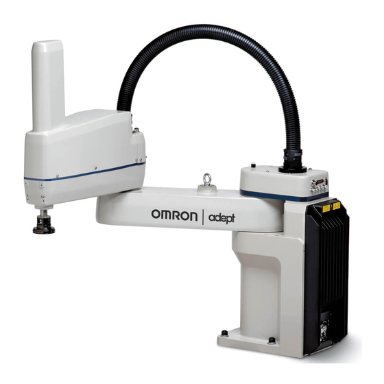
Chapter 1: Introduction 1.1 Product Description eCobra robots are four-joint SCARA industrial robots (Selective Compliance Assembly Robot Arm). Joints 1, 2, and 4 are rotational, Joint 3 is translational. See Figure 1-2. NOTE: The descriptions and instructions in this manual apply to the eCobra 600, eCobra 800, and eCobra 800 Inverted robots. -
Page 12: Ecobra Robot Models
1.1 Product Description Figure 1-2. Robot Joint Motions - eCobra 600 Robot Shown Table 1-1. Robot Joint Descriptions Item Description Joint 1 Joint 2 Joint 3 Joint 4 Inner Link Outer Link eCobra Robot Models There are three tiers of eCobra robots, with 600 and 800 mm upright models and an 800 mm Inverted robot in each tier. -
Page 13: Eaib (Amplifiers In Base)
Chapter 1: Introduction eCobra robots of any given size and orientation are identical physically for each of the three tiers. The Pro models offer the fastest performance and the most features and connectivity. The Lite models offer the least. All nine models are covered in this manual. All eCobra robots will typically be connected to a user-supplied PC running the ACE software. -
Page 14: Ecobra Robot Features And Options
1.2 eCobra Robot Features And Options 1.2 eCobra Robot Features And Options The eAIB controller provides varying levels of vision support and connectivity. Some applic- ations might call for more, in which case you could add a SmartController EX and/or a SmartVision MX industrial PC. -
Page 15: Smartcontroller Ex
The T20 pendant provides manual control of an eCobra robot. This is generally used when teaching pick and place locations. Refer to the T20 Pendant User's Guide. NOTE: Omron Adept Technologies, Inc. does not offer a cableless (wireless) pendant. Intelligent Force Sensing... -
Page 16: How Can I Get Help
1.3 How Can I Get Help? 1.3 How Can I Get Help? Refer to the corporate website: http://www.ia.omron.com Related Manuals This manual covers the installation, operation, and maintenance of an eCobra robot system. For additional manuals covering programming the system, reconfiguring installed com- ponents, and adding optional components, see the following table. -
Page 17: Chapter 2: Safety
Chapter 2: Safety 2.1 Dangers, Warnings, and Cautions Alert Levels There are three levels of alert notation used in our manuals. In descending order of import- ance, they are: DANGER: Identifies an imminently hazardous situation which, if not avoided, is likely to result in serious injury, and might result in fatality or severe property damage. -
Page 18: Special Information
2.2 What to Do in an Emergency/Abnormal Situation Safety Barriers To protect personnel from coming in contact with robot unintentionally or objects entering robot’s operation zone, install user-supplied safety barriers in the workcell. Special Information There are several types of notation used to call out special information. IMPORTANT: Information to ensure safe use of the product. -
Page 19: Emergency Stop Circuit And Buttons
Chapter 2: Safety Once the motors are enabled, the robot will wait two seconds and then resume commanded motion, if there is adequate space to maneuver. Emergency Stop Circuit and Buttons The E-Stop provided complies with ISO 10218-1 (Clause 5.5.2), with stop category 1 (per IEC 60204). -
Page 20: Qualification Of Personnel
Figure 2-1. Read Manual and Impact Warning Labels The eCobra robot system must not be used for purposes other than described in Inten- ded Use on page 21. Contact Omron Adept Technologies, Inc. if you are not sure of the suitability for your application. -
Page 21: Robot Behavior
Limiting Devices There are no dynamic or electro-mechanical limiting devices provided by Omron Adept Tech- nologies, Inc. The robot does not have safety-rated soft axis or space limiting. However, the user can install their own safety rated (category 0 or 1) dynamic limiting devices if needed, that comply with ISO 10218-1, Clause 5.12.2. -
Page 22: Non-Intended Use
Cause injury to personnel Damage itself or other equipment Reduce system reliability and performance If there is any doubt concerning the application, ask your your local Omron support to determ- ine if it is an intended use or not. Robot Modifications If the user or integrator makes any changes to the robot, it is their responsibility to ensure that there are no sharp edges, corners, or protrusions. -
Page 23: Robot Safety Guide
Chapter 2: Safety Robot Safety Guide The Robot Safety Guide, which ships with every robot system, provides detailed information on safety for Omron Adept Technologies, Inc. robots. It also gives resources for information on relevant standards. T20 Manual Control Pendant (Option) The protective stop category for the pendant enable switch is category 1, which complies with the requirements of ISO 10218-1. -
Page 25: Chapter 3: Robot Installation
Chapter 3: Robot Installation 3.1 Installation Overview The system installation process is summarized in the following table. NOTE: For multi-robot installations, see the Single and Multiple Robot Con- figuration Guide. Table 3-1. Installation Overview Task to be Performed Reference Location Mount the robot to a flat, secure mounting surface. -
Page 26: Unpacking And Inspecting The Equipment
Do not lay the crate on its side or any other non-upright position; this could damage the robot. The eCobra 600 robot weighs 41 kg (90 lb), the eCobra 800 robot weighs 43 kg (95 lb), and the eCobra 800 Inverted weighs 51 kg (112 lb), all with no options installed. -
Page 27: Environmental And Facility Requirements
NOTE: For robot dimensions, see Dimension Drawings on page 153. 3.6 Mounting an Upright eCobra Robot This section applies to the eCobra 600 and eCobra 800 robots, but not the eCobra 800 Inverted robot. Figure 3-1. eCobra 800 Robot on a Transportation Pallet 14402-000 Rev. -
Page 28: Mounting Surface
3.6 Mounting an Upright eCobra Robot Table 3-3. Lifting Points for Robot while on a Transportation Pallet Item Description Eyebolt for lifting robot after robot has been unbolted from the transportation pallet. Place for forklift or pallet-jack here. WARNING: PERSONAL INJURY OR PROPERTY DAMAGE RISK Only qualified service personnel may install or service the robot system. -
Page 29: Mounting Procedure
Chapter 3: Robot Installation Mounting Procedure 1. Using the dimensions shown in the previous figure, drill and tap the mounting surface for four M12 - 1.75 x 36 mm (or 7/16 - 14 UNC x 1.50 in.) machine bolts (mounting hard- ware is user-supplied). -
Page 30: Mounting An Ecobra 800 Inverted Robot
3.7 Mounting an eCobra 800 Inverted Robot 3.7 Mounting an eCobra 800 Inverted Robot Mounting Surface The eCobra 800 Inverted robot is designed to be mounted in an inverted position. When design- ing the mounting structure, you must account for both load and stiffness. The mounting struc- ture must be rigid enough to prevent vibration and flexing during robot operation. - Page 31 Chapter 3: Robot Installation 183.2 Figure 3-4. Robot in Folded Position (Units in mm) WARNING: PERSONAL INJURY OR PROPERTY DAMAGE RISK Do not attempt to extend the inner or outer links of the robot until the robot has been secured in position. Failure to comply could result in the robot falling and causing either personnel injury or equipment damage.
-
Page 32: Mounting The Front Panel
3.8 Mounting the Front Panel 4. While the robot is still bolted to the transportation pallet, use a forklift or other mech- anical lifting device to lift the robot and position it directly under the mounting surface. Make sure that one person watches the robot carefully as it is lifted and transported, to ensure it does slip or become unbalanced. -
Page 33: Connectors On Robot Interface Panel (Eaib)
Chapter 3: Robot Installation 3.9 Connectors on Robot Interface Panel (eAIB) 24 VDC—for connecting user-supplied 24 VDC power to the robot. The mating connector is provided. Ground Point—for connecting cable shield from user-supplied 24 VDC cable. 200/240 VAC — for connecting 200-240 VAC, single-phase, input power to the robot. The mat- ing connector is provided. -
Page 35: Chapter 4: System Installation
Chapter 4: System Installation This chapter does not cover I/O. Refer to Connecting Digital I/O to the System on page 83. 4.1 System Cables, without SmartController EX The letters in the following figure correspond to the letters in Table 4-1. Cables and Parts Description (without SmartController EX). -
Page 36: List Of Cables And Parts
4.1 System Cables, without SmartController EX The figure above includes the optional T20 pendant, optional SmartVision MX industrial PC, and optional PLC. These items may not be present in your system. NOTE: For additional system grounding information, see Connecting 24 VDC Cable on page 52. - Page 37 Chapter 4: System Installation Item Description Part # User- Notes Standard Option supplied Bypass Plug (H), or T20 Pendant Assembly (W) must be used. T20 Pendant Adapter 10051- Cable The following three items are available, as an option, in the power supply/cable kit 90565-010 VAC Power Cable 04118- 200-240 VAC,...
-
Page 38: Cable Installation Overview
4.1 System Cables, without SmartController EX The XUSR, XMCP, and XFP jumpers intentionally bypass safety connections so you can test the system functionality during setup. WARNING: PERSONAL INJURY RISK Under no circumstances should you run an eCobra system, in production mode, with all three jumpers installed. This would leave the system with no E- Stops. - Page 39 Chapter 4: System Installation Step Connection Description Item Connect Ethernet cable from switch to SmartVision MX, if used. N, O Connect optional camera and cable to SmartVision MX, if used. Connect Ethernet cable from PC to switch if used. T, U NOTE: A front panel ships with each eCobra robot system, but you can choose not to use it if you replace its functionality with equivalent circuits.
-
Page 40: System Cables, With Smartcontroller Ex
4.2 System Cables, with SmartController EX 4.2 System Cables, with SmartController EX The letters in the following figure correspond to the letters in Table 4-3. Cables and Parts Description (with SmartController EX). The numbers in the following figure correspond to the numbers in Table 4-4. -
Page 41: Installing A Smartcontroller Ex Motion Controller
Chapter 4: System Installation Installing a SmartController EX Motion Controller Refer to the SmartController EX User’s Guide for complete information on installing the optional SmartController EX. This list summarizes the main steps. 1. Mount the SmartController EX and Front Panel. 2. - Page 42 4.2 System Cables, with SmartController EX Part Cable and Parts User- Notes Part # Standard Option List supplied Bypass Plug (H), or T20 Pendant (W) must be used. T20 Pendant Bypass 10048- XMCP Jumper Plug Plug (G), T20 Pendant Bypass Plug (H), or T20 Pendant (W) must be used.
-
Page 43: Cable Installation Overview
Chapter 4: System Installation The XUSR, XMCP, and XFP jumpers intentionally bypass safety connections so you can test the system functionality during setup. WARNING: PERSONAL INJURY RISK Under no circumstances should you run an eCobra system, in production mode, with all three jumpers installed. This would leave the system with no E- Stops. -
Page 44: Optional Cables
4.3 Optional Cables Step Connection Part Connect IEEE 1394 cable between SmartController EX and eAIB O, Q SmartServo. Connect optional camera and cable to SmartVision MX, if used. Connect Ethernet cable from PC to switch if used. S, T, U Connect optional PLC to switch, if used. T, V Refer to Configuring a PLC on page 60 for more information. - Page 45 Chapter 4: System Installation XSYSTEM ENET ENET 24 V 3000 ± 50 Servo 200 - 240 V 600 ± 25 SmartController EX 500 ± 25 Figure 4-3. System Cable Diagram with Belt Encoders (Units in mm) 14402-000 Rev. F eCobra User's Guide...
- Page 46 4.3 Optional Cables Table 4-5. Conveyor Belt Encoder Cables Description User- Item Description Part # Standard Option Notes supplied Robot Interface Panel eAIB XBELT IO Adapter Cable 13463- HDB26 Connector Female Belt Branch Connector DB 15 Male Force / EXPIO Branch Con- DB9 Male nector RS232 Branch Connector DB9 Male Belt Y Splitter Cable Con- 09443-...
- Page 47 Chapter 4: System Installation PIN 2 (ENC1_A+) PIN 15 PIN 3 (ENC1_A-) PIN 7 PIN 11 (ENC1_B+) PIN 14 PIN 12 (ENC1_B-) PIN 6 PIN 19 (ENC1_Z+) PIN 13 PIN 9 PIN 1 PIN 8 PIN 1 PIN 20 (ENC1_Z-) PIN 5 PIN 4 (ENC2_A+) PIN 11...
- Page 48 4.3 Optional Cables PIN 1 PIN 15 (ENC1_A+) PIN 8 PIN 7 (ENC1_A-) PIN 3 PIN 1 PIN 2 PIN 4 PIN 14 (ENC1_B+) PIN 5 PIN 6 (ENC1_B-) PIN 7 PIN 3 PIN 6 PIN 13 (ENC1_I+) PIN 8 PIN 5 (ENC1_I-) PIN 6 PIN 4 PIN 2...
-
Page 49: Ace Software
Chapter 4: System Installation PIN 15 PIN 2 (ENC1_A+) PIN 7 PIN 3 (ENC1_A-) PIN 14 PIN 11 (ENC1_B+) PIN 6 PIN 12 (ENC1_B-) PIN 13 PIN 19 (ENC1_Z+) PIN 20 (ENC1_Z-) PIN 5 PIN 8 PIN 1 PIN 11 PIN 4 (ENC2_A+) PIN 3 PIN 5 (ENC2_A-) -
Page 50: Connecting 24 Vdc Power To Robot
4.5 Connecting 24 VDC Power to Robot 1. Insert the ACE software media into your PC. If Autoplay is enabled, the menu is displayed. If Autoplay is disabled, you will need to manually access the media content. NOTE: The online document that describes the installation process opens in the background when you select one of software installation steps below. -
Page 51: Vdc Mating Connector
See the fol- lowing table for a recommended power supply. Table 4-7. Recommended 24 VDC Power Supply Mount Vendor Name Model Ratings OMRON S8FS-G15024C 24 VDC, 6.5 A, 150 W Front Mount OMRON S8FS-G15024CD 24 VDC, 6.5 A, 150 W... -
Page 52: Creating 24 Vdc Cable
4.5 Connecting 24 VDC Power to Robot NOTE: The 24 VDC cable is not supplied with the system, but is available in the optional Power Cable kit. See List of Cables and Parts on page 41. Creating 24 VDC Cable 1. - Page 53 Chapter 4: System Installation eCobra Robot – – SmartVision MX SmartController EX Figure 4-9. User-Supplied 24 VDC Cable, Power Supply Table 4-9. User-Supplied 24 VDC Cable, Power Supply Description Item Description User-supplied Power Supply, 24 VDC Optional Equipment User-supplied, Shielded Power Cable Circuit Protection, 8 A max. Shield - attach from user-supplied cable to ground screw on eCobra robot interface panel.
-
Page 54: Connecting 200-240 Vac Power To Robot
4.6 Connecting 200-240 VAC Power to Robot CAUTION: PROPERTY DAMAGE RISK The 24 VDC output must be less than 300 W peak or 8 Amp (max) in-line cir- cuit protection must be provided, separately, for each connected robot, SmartController EX, and SmartVision MX. NOTE: In order to maintain compliance with standards, we recommend that DC power be delivered over a shielded cable, with the shield connected to frame ground at both ends of the cable. - Page 55 Chapter 4: System Installation Table 4-11. Typical Robot Power Consumption Average RMS Current Peak Power eCobra Robot Move Power (W) No load—Adept cycle 1.56 1559 5.5 kg—Adept cycle 2.25 2061 5.5 kg—all joints move 4.00 2667 No load—Adept cycle 1.71 1406 5.5 kg—Adept cycle 2.41...
- Page 56 4.6 Connecting 200-240 VAC Power to Robot In the industrial environment, nonperiodic overvoltage peaks may appear on mains power supply lines as a result of power interruptions to high-energy equipment (such as a blown fuse on one branch in a 3-phase system). This will cause high current pulses at relatively low voltage levels.
- Page 57 Chapter 4: System Installation eCobra Robots 1Ø 200–240 VAC Figure 4-11. Single-Phase Load across L1 and L2 of a Three-Phase Supply Table 4-13. Three-phase Power Supply Description Item Description 3 Ø, 200-240 VAC 200 -240 VAC User-supplied fuses, slow blow, 10 A User-supplied AC Power Cable L = Line 1 N = Line 2...
-
Page 58: Ac Mating Connector
4.6 Connecting 200-240 VAC Power to Robot AC Mating Connector The AC mating connector is supplied with each system. It is shipped in the cable/accessories box. The supplied plug is internally labeled for the AC power connections (L, E, N). Table 4-14. -
Page 59: Connecting Ac Power Cable
Chapter 4: System Installation Figure 4-12. AC Power Mating Connector Table 4-15. AC Power Mating Connector Description Item Description Earth Neutral Removable Bushing Cable Clamp Line Connecting AC Power Cable 1. Connect the unterminated end of the AC power cable to your facility AC power source. See AC Power Diagrams on page 56. -
Page 60: Grounding Robot-Mounted Equipment
4.8 Configuring a PLC washers installed in the grounding hole. The user is responsible for supplying the ground wire to connect to earth ground. Figure 4-13. (1) Ground Point on Robot Base and (2) Ground Label NOTE: The resistance of the earth ground conductor must be ≤ 10 Ω. Grounding Robot-Mounted Equipment The following two parts of an eCobra robot are not grounded to protective earth: the Joint 3 quill and the tool flange. - Page 61 Chapter 4: System Installation 4. Select SYSTEM_SECTION > eplc_autostart. 5. Click Edit (or double-click the selection). 6. Check the eplc_autostart box. It defaults to unchecked. 14402-000 Rev. F eCobra User's Guide...
-
Page 62: Installing User-Supplied Safety Equipment
4.9 Installing User-Supplied Safety Equipment 7. Save the configuration by clicking Accept and then Yes. 4.9 Installing User-Supplied Safety Equipment The user is responsible for installing safety barriers to protect personnel from coming in con- tact with the robot unintentionally. Depending on the design of the workcell, safety gates, light curtains, and emergency stop devices can be used to create a safe environment. - Page 63 Chapter 4: System Installation Table 4-16. Contacts Provided by the XUSR Connector Description Comments Pairs Voltage-Free Contacts Provided by Customer 1, 14 User E-Stop CH 1 (mushroom N/C contacts, Shorted if NOT Used push-button, safety gates, etc.) 2, 15 User E-Stop CH 2 (same as pins N/C contacts, Shorted if NOT Used 1, 14) 3, 16...
- Page 64 4.9 Installing User-Supplied Safety Equipment Table 4-17. Contacts Provided by the XFP Connector Description Requirements for User- Pairs Supplied Front Panel Voltage-Free Contacts Provided by Customer 1, 9 Front Panel E-Stop CH 1 User must supply N/C con- tacts 2, 10 Front Panel E-Stop CH 2 User must supply N/C con- tacts...
- Page 65 Chapter 4: System Installation Table 4-18. Remote Pendant Connections on the XMCP Connector Pin XMCP Description (15-Pin D-Sub) 1, 9 Pendant E-Stop Push-button CH 1 2, 10 Pendant E-Stop Push-button CH 2 3, 11 Pendant Enable CH 1 (Hold-to-run) 4, 12 Pendant Enable CH 2 (Hold-to-run) Serial GND/Logic GND Pendant TXD: “eV+ to Pendant TXD”...
- Page 66 4.9 Installing User-Supplied Safety Equipment XSYSTEM-31 XSYSTEM-32 XSYSTEM-31 (XFP-6) (XFP-1) (XFP-2) XSYSTEM-3 (XFP-5) XSYSTEM-33 (XFP-13) XSYSTEM-34 (XFP-14) XSYSTEM-20 (XFP-10) (XFP-9) (XPND-7) (XPND-6) XSYSTEM-5 (XFP-3) (XFP-4) XSYSTEM-24 (XPND-23) (XPND-24) XSYSTEM-4 XSYSTEM-19 (XUSR-1) (XUSR-2) (XFP-11) (XFP-12) Coil Coil (XUSR-14) (XUSR-15) XSYSTEM-13 XSYSTEM-43 (XUSR-3) (XUSR-4) XSYSTEM-12 (XUSR-9)
- Page 67 Chapter 4: System Installation Table 4-19. E-Stop Circuit on XUSR and XFP Connectors Description Item Description ESTOP 24 V Source ESTOP Ground Front Panel ESTOP Pushbutton T20 ESTOP Pushbutton User E-Stop and Gate Interlock (jumper closed when not used, must open both chan- nels independently if used) LINE E-Stop (external user E-Stop system) T20 Pendant Enable Muted Safety Gate - Active in auto mode only (jumper closed when not used)
-
Page 68: Emergency Stop Circuits
4.9 Installing User-Supplied Safety Equipment ESTOPSRC 15PDSUBM ESTOPFP1 24 VS ESTOPFP2 MANUALSRC1 5 VD MANUALRLY1 MANUALSRC2 MANUALRLY2 HPLT5V HIPWRLT HIPWRREQ SYSPWRLT HPLT5 V MANUALSRC2 5 VD 24 VS ESTOPSRC MANUALSRC1 SYSPWRLT SWL1 2-PIN_MINI HIPWRLT MANUALRLY2 ESTOPFP2 MANUALRLY1 HIPWRREQ ESTOPFP1 Figure 4-15. Front Panel Schematic Table 4-20. - Page 69 MCP ENABLE, or the Muted Safety gate. If you have a specific need in this area, contact your local Omron support for information on alternate indicating modes. Two pairs of pins on the XUSR connector (pins 7, 20 and 8, 21) provide voltage-free contacts, one for each channel, to indicate whether the E-Stop chain, as described above, on that channel is closed.
-
Page 70: Remote Manual Mode
4.9 Installing User-Supplied Safety Equipment WARNING: PERSONAL INJURY RISK If you want the cell gate to always cause a robot shutdown, wire the gate switch contacts in series with the user E-Stop inputs. Do not wire the gate switch into the muted safety gate inputs. Remote Manual Mode The Front Panel provides for a Manual Mode circuit. -
Page 71: Remote High Power On/Off Control
Chapter 4: System Installation Remote High Power On/Off Control The easiest and most effective way to provide the high power on/off control in a remote loc- ation is to mount the Front Panel in the desired location with an extension cable. However, if the user needs to control high power on/off from other control equipment or from a location other than the Front Panel, then a custom splitter cable will be required. -
Page 72: Remote Pendant Usage
4.9 Installing User-Supplied Safety Equipment Customers can build an extension cable to place the Front Panel in a remote location. The extension cable must conform to the following specifications: Wire Size: must be larger than 26 AWG. Connectors: must be 15-pin, standard D-sub male and female. Maximum cable length is 10 meters. -
Page 73: Chapter 5: System Operation
Chapter 5: System Operation 5.1 Robot Status LED Description The robot Status LED indicator is located on the top of the upright robots, and at the top of the status panel for the eCobra Inverted robot. The blinking pattern indicates the status of the robot. -
Page 74: Status Panel
5.2 Status Panel Fault Codes The displayed fault code will continue to be displayed even after the fault is corrected or addi- tional faults are recorded. All displayed faults will be cleared from the display, and reset to a no-fault condition, upon successfully enabling high power to the robot, or power cycling the 24 V supply to the robot. - Page 75 Turn high power back on and restart the program. If the error persists, con- tact your local Omron support. *RSC Power Fail- -670 A loss of AC power was Check user AC power ure* detected.
- Page 76 / disabled via ACE. None Firmware version mis- Contact your local match. Omron support. *1394 com- -927 The IEEE 1394 com- This will occur nor- munications munications system has mally if the...
- Page 77 PA-4 status lights. Refer to Adept PA-4 Power Chassis User's Guide for details. Contact your local Omron support if the error persists. *Power system -1115 The high-voltage DC bus Contact your local failure* Code 2 to the regenerative Omron support.
- Page 78 If it ted rate when power occurs unex- was enabled. pectedly, contact your local Omron support. None A servo task has overrun If the problem per- its allotted execution win- sists, contact your dow.
- Page 79 Error Error Explanation User Action Code Message Code ienced a failure on chan- local Omron support. nel 1 during the cyclic check of dual-channel power system. This may indicate a welded relay contact or other hard- ware failure. *Safety System...
-
Page 80: Brakes
Delay. None Software watchdog If the problem per- timer timeout. On some sists, contact your products it is normal for local Omron support. this to occur moment- arily during a servo reset. *Safety System -1109 An error was detected Contact your local... -
Page 81: Remote Brake Release Feature
Chapter 5: System Operation robot status panel, as shown in Figure 5-2. When system power is on, pressing this button releases the brake, which allows movement of Joint 3. NOTE: 24 Volt robot power must be on to release the brake. If this button is pressed while high power is on, high power will automatically shut off. - Page 82 5.4 Front Panel 1. XFP connector Connects to the XFP connector on the eAIB XSYSTEM cable (or the optional SmartCon- troller EX, if one is being used). 2. System 5 V Power-On LED Indicates whether or not power is connected to the robot. 3.
-
Page 83: Connecting Digital I/O To The System
You can connect digital I/O to the system in several different ways. See the following table and figure. NOTE: A typical IO Blox configuration is shown in Figure 5-4. Other con- figurations may be possible. Contact your local Omron support for more inform- ation. Table 5-3. Digital I/O Connection Options... -
Page 84: Default Digital I/O Signal Configuration
5.5 Connecting Digital I/O to the System Default Digital I/O Signal Configuration eCobra Robot SmartController EX XSYSTEM ENET ENET Servo 200 - 240V Figure 5-4. Connecting Digital I/O to the System Table 5-4. Default Digital I/O Signal Configuration, Single Robot, no SmartController EX Item Location Type Signal Range... - Page 85 Chapter 5: System Operation Item Location Type Signal Range IO Blox 6 Inputs 1073–1080 Outputs 0073–0080 IO Blox 7 Inputs 1081–1088 Outputs 0081–0088 IO Blox 8 Inputs 1089–1096 Outputs 0089–0096 For Multi-Robot systems, see Single and Multiple Robot Configuration Guide. Table 5-5.
-
Page 86: Eaib Xio Connector Signals
5.5 Connecting Digital I/O to the System Item Location Type Signal Range IO Blox 8 Inputs 1313–1320 Outputs 0281–0288 For Multi-Robot systems, see Single and Multiple Robot Configuration Guide. eAIB XIO Connector Signals The XIO connector on the robot interface panel offers access to digital I/O, 12 inputs and 8 out- puts. -
Page 87: Xio Input Signals
Chapter 5: System Operation Signal eV+ Signal Pin No. Designation Bank Number Output 2 0098 Output 3 0099 Output 4 0100 Output 5 0101 Output 6 0102 Output 7 0103 Output 8 0104 Pin 9 Pin 1 Pin 18 Pin 10 Pin 26 Pin 19 XIO Input Signals... - Page 88 5.5 Connecting Digital I/O to the System XIO Input Specifications Table 5-7. XIO Input Specifications Operational voltage range 0 to 30 VDC OFF state voltage range 0 to 3 VDC ON state voltage range 10 to 30 VDC Typical threshold voltage = 8 VDC Operational current range 0 to 7.5 mA...
- Page 89 Chapter 5: System Operation Typical Input Wiring Example 1097 1098 1099 1100 1101 1102 +24V 1103 1104 1105 1106 1107 1108 +24V Figure 5-5. Typical User Wiring for XIO Input Signals NOTE: All input signals can be used for either sinking or sourcing con- figurations.
-
Page 90: Xio Output Signals
5.5 Connecting Digital I/O to the System Table 5-8. Typical User Wiring for XIO Input Signal Description Item Description Supplied Equipment User-supplied Equipment Equivalent Circuit Wiring Terminal Block Typical User Input Signals (part present sensor, feeder empty sensor, part jammed sensor, sealant ready sensor, etc.) Bank 1 configured for Sinking (NPN) inputs Bank 2 configured for Sourcing (PNP) inputs Input Bank 1... - Page 91 Chapter 5: System Operation XIO Output Specifications Table 5-9. XIO Output Circuit Specifications Parameter Value Power supply voltage range See Specifications for 24 VDC Power on page 50. ≤ 700 mA Operational current range, per chan- ≤ 1.0 A @ 50° C ambient Total Current Limitation, all chan- total nels on.
- Page 92 5.5 Connecting Digital I/O to the System Typical Output Wiring Example +24 VDC 0097 0098 0099 0100 0101 0102 0103 0104 Figure 5-6. Typical User Wiring for XIO Output Signals Table 5-10. Typical User Wiring for XIO Output Signal Description Item Description Supplied Equipment User-supplied Equipment...
-
Page 93: Xio Breakout Cable
Chapter 5: System Operation XIO Breakout Cable The XIO Breakout cable is available as an option—see the following figure. This cable connects to the XIO connector on the eAIB, and provides flying leads on the user’s end, for connecting input and output signals in the workcell. The cable length is 5 M (16.4 ft). For the wire chart on the cable, see the following table. -
Page 94: Starting The System For The First Time
5.6 Starting the System for the First Time Signal Pin No. Designation Wire Color Input 1.2 Orange Input 2.2 Orange/Black Input 3.2 Gray Input 4.2 Gray/Black Input 5.2 Violet Input 6.2 Violet/White Output 1 Pink Output 2 Pink/Black Output 3 Light Blue Output 4 Light Blue/Black... -
Page 95: Verifying Installation
Chapter 5: System Operation Verifying Installation Verifying that the system is correctly installed and that all safety equipment is working cor- rectly is an important process. Before using the robot, make the following checks to ensure that the robot system has been properly installed. WARNING: PERSONAL INJURY OR PROPERTY DAMAGE RISK After installing the robot, you must test it before you use it for the first time. -
Page 96: Turning On Power
Double-click the ACE icon on your Windows desktop, From the Windows Start menu bar, select: Start > Programs > Omron > ACE x.y where x is the ACE major version, and y is the ACE minor version. For example, for ACE 3.6, it would be: Start >... -
Page 97: Enabling High Power
Chapter 5: System Operation Enabling High Power After you have started ACE and connected to the controller, enable high power to the robot motors. Using ACE to Enable High Power 1. From the ACE main menu, click the Enable High Power icon. 2. -
Page 99: Chapter 6: Maintenance
Clause 5.2.4 of ISO 10218-1. The following parts are the only field-replaceable parts: Table 6-1. Field-replaceable Parts Part Omron Adept Technologies, Inc. Part Number Encoder battery 09977-000 (3.6 V, 6.8 Ah) (This has replaced part number 02704-000) eCobra 600... -
Page 100: Warning Labels
6.3 Warning Labels Table 6-2. Inspection and Maintenance Item Period Reference Safety Labels 1 week Check E-Stop, enable and key 6 months Warning Labels on page 100 switches, and barrier interlocks Check robot mounting bolts 6 months Checking Robot Mounting Bolts on page 103 Check for signs of oil around 3 months Checking for Oil Leakage on page 103. -
Page 101: Rev. F Ecobra User's Guide
Chapter 6: Maintenance Figure 6-1. Read Manual and Impact Warning Label This is placed in the following location on the robot: Figure 6-2. Location of Read Manual and Impact Warning Label (Inverted Model Shown). 14402-000 Rev. F eCobra User's Guide... - Page 102 6.3 Warning Labels Gravity/Brake Release Label, 18272-000 This label warns about the possibility of a robot joint dropping suddenly when the brake release is pressed because of gravity. In the case of the eCobra, this applies to the quill and tool flange. Figure 6-3.
-
Page 103: Checking Safety Systems
WARNING: ELECTROCUTION RISK Remove all power to the robot before opening the eAIB chassis. Contact Omron Adept Technologies, Inc. if you find any signs of oil in these areas. 14402-000 Rev. F eCobra User's Guide... -
Page 104: Lubricating Joint
6.7 Lubricating Joint 3 6.7 Lubricating Joint 3 Use LG-2 Grease (Lithium Soap/Synthetic Hydrocarbon), P/N: 90401-04029. CAUTION: PROPERTY DAMAGE RISK Using improper lubrication products on an eCobra robot may cause damage to the robot. 1. Turn off main power to the robot. If an optional SmartController EX is being used, turn off main power to that, too. - Page 105 Chapter 6: Maintenance Figure 6-5. (1) Quill Shaft, (2) Vertical Groove Lubrication Points, Top-view Looking Down Figure 6-6. (1) Upper Quill Spiral Groove Lubrication Point 6. Press the brake button and move Joint 3 to the bottom of its travel. Remove any existing grease with a clean, lint-free, soft cloth. 7.
- Page 106 6.7 Lubricating Joint 3 figure below). Figure 6-7. (1) Lower Quill Grease Locations 8. Move Joint 3 up and down several times to spread the grease evenly. 9. Remove 24 VDC power from the robot. 10. Reinstall the outer link cover. For the Cleanroom version, reinstall or replace the bellows.
-
Page 107: Replacing The Eaib Chassis
Chapter 6: Maintenance 6.8 Replacing the eAIB Chassis CAUTION: PROPERTY DAMAGE RISK Follow appropriate ESD procedures during the removal/replacement phases. Removing the eAIB Chassis 1. Switch off the 24 VDC input supply to the chassis. 2. Switch off the 200/240 VAC input supply to the chassis. 3. - Page 108 6.8 Replacing the eAIB Chassis The chassis can be laid flat or placed to the right side of the robot for better access. Figure 6-9. Opening and Removing Chassis 10. Disconnect the white amplifier cable from the (1) amplifier connector located on the chassis bracket.
-
Page 109: Installing A New Eaib Chassis
Chapter 6: Maintenance 11. Carefully disconnect the INT1 (2), INT2 (3), ENC1 (4), and ENC2 (5) cables from their connectors on the ePMAI board (6), by disengaging the securing latches. See the pre- vious figure. 12. Using a 5 mm hex wrench, disconnect and remove the ground wire from the chassis. Keep the screw for reassembly later. -
Page 110: Commissioning A System With An Eaib
6.9 Commissioning a System With An eAIB 9. Connect the eAIB XSYSTEM cable to the chassis XSYSTEM connector, or, if you are using an optional SmartController EX, connect the eAIB XSYS cable to the chassis XSYSTEM connector. 10. Connect any other cables that were connected to the chassis, such as XIO, RS-232, 1394, or any others. - Page 111 Chapter 6: Maintenance This verifies that the hardware E-Stop is functioning correctly. Teach Restrict Configuration This sets the hardware Teach Restrict maximum speed to factory specifications. Teach Restrict Verification This verifies that the hardware Teach Restrict is functioning correctly. The initial utility screen will tell you which functions are commissioned. If a function is not commissioned, its verification wizard will not be displayed.
-
Page 112: E-Stop Configuration Utility
6.9 Commissioning a System With An eAIB NOTE: This is the only time that this jumper will be used. It is part num- ber 11901-000, and must be removed for Verification and normal oper- ation. Figure 6-13. eAIB Commissioning Jumper A pendant is required for the Teach Restrict verification. -
Page 113: E-Stop Verification Utility
Chapter 6: Maintenance E-Stop Verification Utility This utility verifies that the hardware E-Stop parameters are set correctly and that the hard- ware E-Stop is working. The hardware E-Stop must have already been configured for this wizard to run. NOTE: If the commissioning jumper is plugged into the XBELTIO jack on the eAIB, remove it before you start this procedure. -
Page 114: Teach Restrict Verification Utility
6.9 Commissioning a System With An eAIB 4. Click Finish. 5. Reboot V+: Controller > Control > Reboot V+ NOTE: This can also be accomplished by momentarily removing 24 VDC power from the controller. Teach Restrict Verification Utility This utility verifies that the Teach Restrict parameters are set correctly and that the hardware Teach Restrict maximum speed control is working. -
Page 115: Replacing A Microsd Card
Chapter 6: Maintenance If the Automatic Mode Procedure fails, you will not be allowed to proceed with the Manual Mode. Manual Mode Procedure The manual mode of this verification requires the use of a pendant. For this verification, the Front Panel keyswitch must be in Manual mode. 1. - Page 116 6.10 Replacing a MicroSD Card Figure 6-14. Connector-end of eAIB (with cables removed) 5. Remove the (1) shoulder screw and (2) MicroSD retention bracket. See the previous fig- ure. Save both of these for re-installation. 6. Remove the installed MicroSD card. This is removed by pressing it all the way in, and then releasing.
-
Page 117: Installing A Microsd Card Into An Eaib
Chapter 6: Maintenance Figure 6-15. (top) MicroSD Card In and (bottom) Partially Out Continue with the following section. Installing a MicroSD Card into an eAIB This procedure assumes you have already removed the MicroSD card. 1. Install the MicroSD card into its holder in the eAIB controller. Press the card in all the way, and gently let it slide back out to a stop. -
Page 118: Battery Replacement Time Periods
6.11 Replacing the Encoder Battery Pack Battery Replacement Time Periods If the robot is kept in storage and not in production, or the 24 VDC supply, is applied less than half the time, while the encoder backup battery is in the robot, then the battery should be replaced every 2 years. -
Page 119: Changing The Lamp In The Front Panel High-Power Indicator
Chapter 6: Maintenance 9. The battery cable assembly has two sets of connectors. Locate the secondary (unused) battery cable in the wire bundle in the base area. 10. Place the new battery pack next to the original one, but do not disconnect the original one. - Page 120 6.12 Changing the Lamp In the Front Panel High-Power Indicator 6. Carefully pull the front cover away from the body of the Front Panel. You will encounter some resistance, as there are three plug-type connectors that you need to disconnect as you pull the front cover away from the body. NOTE: Separate the cover from the body slowly to avoid damaging the two wires that go between the LED and the PC board inside the body.
- Page 121 Chapter 6: Maintenance Table 6-3. Lamp Body Contact Alignment Description Item Description Back side of Front Panel Wires between LED and body of Front Panel. Be careful when separating Front Panel from body to avoid damaging the wires. High Power ON / OFF Lamp Body 14402-000 Rev.
-
Page 123: Chapter 7: Optional Equipment Installation
Chapter 7: Optional Equipment Installation 7.1 Installing End-Effectors The user is responsible for providing and installing any end-effector or other end-of-arm tool- ing. End-effectors can be attached to the tool flange using four M6 screws. See Figure 8-6. for a detailed dimension drawing of the tool flange. -
Page 124: Installing The Flange
7.2 Removing and Installing the Tool Flange flange behind the setscrew. Figure 7-1. Tool Flange Removal Details Table 7-1. Tool Flange Removal Description Item Description Tool Flange Assembly Quill Shaft Setscrew M4 Socket-head Cap Screws Installing the Flange 1. Make sure the steel ball is in the setscrew hole inside the flange. Hold it in place with your finger as you get ready to install the flange. -
Page 125: User Connections On The Robot
Chapter 7: Optional Equipment Installation 7.3 User Connections on the Robot User Air Lines There are five user air line connectors on the robot user panel on the back of Joint 1. See Figure 7-2. The five air lines run through the robot up to another set of five matching connectors on the top of the outer link. -
Page 126: User Electrical Lines
7.4 Internal User Connectors User Electrical Lines There is a 25-pin male connector (24 conductor) on the robot user panel on the back of Joint 1 for user electrical lines. See Figure 7-2. This connector is wired directly to a 25-pin female con- nector on the top of the outer link. -
Page 127: Solnd Connector
Chapter 7: Optional Equipment Installation NOTE: When the Outer link cover is removed, you see the label shown above. Do not remove the J3-ENC or J4-ENC encoder cable connectors from their sock- ets. If they are removed, the calibration data will be lost and the robot must be run through a factory recalibration process, which requires special software and tools. -
Page 128: Op3/4 Connector
7.4 Internal User Connectors OP3/4 Connector This 4-pin connector provides the output signals for a second set of optional robot hand valve solenoids, or other user-supplied devices. See the following table and figure. For the connector location, see Figure 7-4. Table 7-5. -
Page 129: Eoapwr Connector
Chapter 7: Optional Equipment Installation Table 7-6. OP3/4 and SOLND Circuit Descriptions item Description Details SOLND Connector Circuit For optional Robot Solenoid Kit installation or other user-supplied devices. OP3/4 Connector Circuit For optional second set of solenoids or other user- supplied devices. +24 VDC (equivalent circuit) EOAPWR Connector This 4-pin connector provides 24 VDC power and ground for user applications. -
Page 130: Estop Connector
7.4 Internal User Connectors Parameter Value Ω On-state resistance (I = 0.5 A) ≤ 0.32 @ 85° C ≤ 25 µA Output leakage current Turn-on response time 125 µsec max., 80 µsec typical (hardware only) Turn-off response time 60 µsec max., 28 µsec typical (hardware only) (+V - 65) ≤ V ≤... - Page 131 Chapter 7: Optional Equipment Installation Pin 1 Pin 2 Figure 7-7. Internal E-Stop Connector Circuit Table 7-10. Internal E-Stop Connector Circuit Description Item Description Typical E-Stop Connector Circuit User-supplied normally-closed contact. Can be connected to a break-away sensor to cause an E-Stop condition when circuit is open. NOTE: This function is disabled by default.
-
Page 132: Mounting Locations For External Equipment
7.5 Mounting Locations for External Equipment Figure 7-8. Robot Object Editor with Break-away E-Stop Parameter Field NOTE: When the Break-away E-Stop function has been enabled, you must con- nect a normally-closed circuit to pins 1 and 2 of the ESTOP connector, as described above. -
Page 133: Tools Required
3-way valves. By removing the plugs, the user can use the assembly as 4-way valves, if needed. The Solenoid Kit for the eCobra robots is available through Omron Adept Technologies, Inc. Contact your sales representative for current price and availability. -
Page 134: Installation
Installation 1. Turn off all power to the robot. 2. Remove two screws on an eCobra 600 (three screws on an 800) on each side of the outer link cover. Remove two screws on top and remove the cover. For the IP65 version, refer to Robot Outer Link Cover Removal and Reinstallation on page 178 for instructions on removing the link cover. - Page 135 Chapter 7: Optional Equipment Installation Valve 2. Figure 7-10. Solenoid Mounting Bracket with Connector and Spare Air Line Table 7-12. Robot Solenoid Kit Description Item Description Spare air line Connector for solenoid valves (labeled SOLND) Pem nuts to mount to solenoid manifold 4.
- Page 136 7.6 Installing the Robot Solenoid Kit Figure 7-11. Solenoid Placement Using Mounting Hardware Table 7-13. Solenoid Placement Description Item Description Air intake coupling with spare air line Tubing connected to output port Mounting screws for solenoid assembly 9. Install the appropriate lengths of 5/32 inch plastic tubing (supplied) into the two output ports on the manifold.
- Page 137 Chapter 7: Optional Equipment Installation Figure 7-12. Removing the Cable Strap Plate Table 7-14. Removing the Cable Strap Plate Description Item Description Two M5 x 8 screws Cable Strap Plate c. Remove the four screws from the Joint 1 cover. See the following figure. Retain the screws for re-assembly.
- Page 138 7.6 Installing the Robot Solenoid Kit Table 7-15. Connecting Spare Air line to User Connector Description Item Description Joint 1 cover lifted to access spare air line. User air fitting for connecting spare line. Remove factory installed tubing first. Tubing bundle containing spare air line. 12.
-
Page 139: Testing
Chapter 7: Optional Equipment Installation NOTE: This 6 mm User Air connector and the 6 mm User Air connector at the top of Figure 7-2. are not available for other uses after this modification. 16. Reinstall the Joint 1 cover, taking care to ensure that all tubing is inside the cover and nothing gets crimped or pinched while pushing the cover into position. -
Page 140: Installing The Camera Bracket Kit
7.7 Installing the Camera Bracket Kit 4. Select Signal 3001 and Signal 3002 (the first two blocks) to activate the solenoids one at a time. 5. The selected blocks will turn green, to indicate they are active. CAUTION: PERSONAL INJURY RISK Disconnect robot air pressure until this test has been done to prevent unse- cured pneumatic lines from accidentally injuring personnel. -
Page 141: Procedure
Chapter 7: Optional Equipment Installation Procedure 1. Install the camera plate to the outer link with four M5 x 12 mm screws. See Figure 7-15. as you perform this procedure. 2. Install the two camera brackets to the camera plate with two stainless steel washers and two M4 x 12 mm screws for each bracket. -
Page 142: Installing Adjustable Hardstops
7.8 Installing Adjustable Hardstops 7.8 Installing Adjustable Hardstops We offer an adjustable hardstop kit for Joint 1 and Joint 2 on the eCobra robots. These are user- installed options that can be used to limit the work envelope of the robot. The part number for the kit is 02592-000. - Page 143 Chapter 7: Optional Equipment Installation NOTE: The two sides do not have to have a hardstop in the same position, i.e., you can use Position 1 on one side, and Position 2 (or none) on the other, if you choose. Modifying Joint Limit Softstop Locations for Joint 1 After installing the adjustable hardstops, you must modify the softstop locations using the ACE software.
- Page 144 7.8 Installing Adjustable Hardstops Figure 7-18. Robot Editor, with Joints Expanded 4. Click the ‘+’ in front of [1], to open the values for joint 1. eCobra User's Guide 14402-000 Rev. F...
- Page 145 Chapter 7: Optional Equipment Installation Figure 7-19. Robot Editor, with Joint 1 Expanded 5. Highlight the current values for joint 1, and replace them with the new values. See the following table for recommended softstop values for Position 1 or Position 2. Table 7-19.
-
Page 146: Joint 2 Adjustable Hardstops
7.8 Installing Adjustable Hardstops Joint 2 Adjustable Hardstops The Joint 2 Adjustable Hardstop kit (shown in the following figure) consists of two curved plates that are the adjustable hardstops, a small, black rectangular device that is the fixed hard- stop, and the required screws to install them. The adjustable hardstop plates can be installed in different locations, depending on how much you need to limit the Joint 2 range of motion. - Page 147 Chapter 7: Optional Equipment Installation Figure 7-21. (1) Joint 2 Adjustable Hardstop Locations Figure 7-22. Screw Locations for Joint 2 Adjustable Hardstops (under side of Inner Link, looking up) 14402-000 Rev. F eCobra User's Guide...
- Page 148 7.8 Installing Adjustable Hardstops Table 7-20. Screw Locations for Joint 2 Adjustable Hardstops Description Item Description Joint 2 Positive Direction Joint 2 Negative Direction Joint 2 Right Hardstop Plate, Installed in -81 Degree Position Joint 2 Left Hardstop Plate, Installed in +81 Degree Position Joint 2 Fixed Hardstop Device 12 Thru Holes for M5 x 10 Screws, for Installing Joint 2 Hardstops, Located 30 Degrees Apart...
- Page 149 Chapter 7: Optional Equipment Installation Modifying Joint Limit Softstop Locations for Joint 2 After installing the adjustable hardstops, you must modify the softstop locations using the ACE software. 1. From the ACE software, select the robot in the tree structure pane. 2.
- Page 150 7.8 Installing Adjustable Hardstops Figure 7-25. Robot Editor, with Joints Expanded 4. Click the ‘+’ in front of [2], to open the values for joint 2. Figure 7-26. Robot Editor, with Joint 2 Expanded eCobra User's Guide 14402-000 Rev. F...
- Page 151 Chapter 7: Optional Equipment Installation 5. Highlight the current values for joint 2, and replace them with the new values. See the following table for recommended softstop values. Table 7-21. Joint 2 Ranges for Adjustable Hardstops Recommended Hardstop Value Joint Limit Softstop J2 Hardstop Position 1 Lower limit: –...
-
Page 153: Chapter 8: Technical Specifications
Chapter 8: Technical Specifications 8.1 Dimension Drawings Figure 8-1. eCobra 600 Robot Top and Side Dimensions (Units in mm) 14402-000 Rev. F eCobra User's Guide... - Page 154 8.1 Dimension Drawings Table 8-1. eCobra 600 Robot Top and Side Dimension Description Item Description Required Clearance to Open eAIB Chassis 31 mm Required Cable Clearance Figure 8-2. eCobra 800 Robot Top and Side Dimensions (Units in mm) eCobra User's Guide...
- Page 155 Chapter 8: Technical Specifications Table 8-2. eCobra 800 Robot Top and Side Dimension Description Item Description Required Clearance to Open eAIB Chassis 31 mm Required Cable Clearance 160.0 171.5 800.0 278.5 18.0 32.5 729.0 Figure 8-3. eCobra 800 Inverted Robot Top and Side Dimensions (Units in mm) 14402-000 Rev.
- Page 156 8.1 Dimension Drawings 2X M4x0.7-6H +.10 -.03 2X M4x0.7-6H Figure 8-4. Dimensions of the Camera Bracket Mounting Pattern, Upright eCobra (Units in mm) Table 8-3. Camera Bracket Mounting Pattern Dimension Description, Upright eCobra robot Item Description 457 mm to Base of robot eCobra User's Guide 14402-000 Rev.
- Page 157 Chapter 8: Technical Specifications +.10 Ø 3.0 -.03 4x M4x0.7-6H Figure 8-5. Dimensions of the Camera Bracket Mounting Pattern, Inverted eCobra (Units in mm) 14402-000 Rev. F eCobra User's Guide...
- Page 158 8.1 Dimension Drawings 12.0 20.0 4.14 6.80 ° +.03 Ø 41.15 45° –.00 +.01 Ø 6.0 – 0 Ø 63.0 ° Ø 50.0 4x M6 x 1- 6H Thru R 3.56 5.08 Ø M3 X 0.5-6 H Thru Figure 8-6. Tool Flange Dimensions for eCobra Robots (Units in mm) eCobra User's Guide 14402-000 Rev.
- Page 159 Chapter 8: Technical Specifications Table 8-4. Tool Flange Description Item Description Dowel Pin Hole User Ground 4X M4x0.7 - 6H 4X M4x0.7 - 6H Figure 8-7. External Tooling on Top of Robot Arm, Upright eCobra (Units in mm) Table 8-5. External Tooling Description, Upright eCobra Item Description Inner Link Mounting Locations...
- Page 160 8.1 Dimension Drawings 76 - eCobra 600 135 - eCobra 800 4X M4x0.7-6H Figure 8-9. External Tooling on Underside of Outer Link, Upright eCobra (Units in mm) 160.0 60.0 105.0 171.5 800.0 278.5 Figure 8-10. External Tooling on Top of Robot Arm, Inverted eCobra (Units in mm) eCobra User's Guide 14402-000 Rev.
- Page 161 Chapter 8: Technical Specifications 4X M4x0.7-6H Figure 8-11. External Tooling on Underside of Outer Link, Inverted eCobra (Units in mm) 14402-000 Rev. F eCobra User's Guide...
- Page 162 105° 105° 150° 150° Figure 8-12. eCobra 600 Robot Working Envelope Table 8-6. eCobra 600 Robot Working Envelope Description Item Description Maximum Intrusion Contact Radius (R 647 mm) Maximum Radial Reach Functional Area (R 600 mm) Minimal Radial Reach (R 162.6 mm)
- Page 163 Chapter 8: Technical Specifications 105° 105° 157.5° 157.5° Figure 8-13. eCobra 800 Robot Working Envelope Table 8-7. eCobra 800 Robot Working Envelope Description Item Description Maximum Intrusion Contact Radius (R 847.3 mm) Maximum Radial Reach Functional Area (R 800 mm) Minimal Radial Reach (R 163.6 mm) Cartesian Limits (300 mm) 14402-000 Rev.
- Page 164 8.1 Dimension Drawings 123.5° 156.5° 156.5° 123.5° 338.0 mm 387.6 mm Figure 8-14. eCobra 800 Inverted Robot Working Envelope Table 8-8. eCobra 800 Inverted Robot Working Envelope Description Item Description Minimum Radial Reach (R 167.0) Maximum Radial Reach Functional Area (R 800.0 mm) Maximum Intrusion Contact Radius (R 847.3 mm) Cartesian Limits (314.0 mm) eCobra User's Guide...
- Page 165 Chapter 8: Technical Specifications 155.0° 155.0° 123.5° 123.5° R 375 R 375 Figure 8-15. eCobra 800 Inverted, IP65, Working Envelope Table 8-9. eCobra 800 Inverted Robot, IP65, Working Envelope Description Item Description Maximum Radial Reach Functional Area (R 800.0 mm) Maximum Intrusion Contact Radius (R 852.12 mm) Minimum Radial Reach (R 179.90 mm) Cartesian Limits (324.0 mm)
-
Page 166: Robot Specifications
8.2 Robot Specifications 8.2 Robot Specifications Physical Table 8-10. eCobra Robot Physical Description eCobra 600 Robot eCobra 800 Robots (both) Reach 600 mm 800 mm Payload—rated 2.0 kg (4.4 lb) 2.0 kg (4.4 lb) Payload—maximum 5.5 kg (12.1 lb) 5.5 kg (12.1 lb) -
Page 167: Performance
Chapter 8: Technical Specifications Performance Table 8-11. eCobra Robot Performance Description eCobra 600 Robot eCobra 800 Robots (both) Moment of Inertia Joint 4 - 450 kg-cm² Joint 4 - 450 kg-cm² (150 lb-in²) - max (150 lb-in²) - max Downward Push Force—Burst,... -
Page 168: Key To Graphs
Meaning Blue Line Payload 33% Red Line Payload 66% Green line Payload 100% Stopping Distance (mm) Stopping Distance (degrees) Stopping Time (seconds) Speed (%) 100% Figure 8-16. Joint 1 Stopping Distance for eCobra 600, in Degrees eCobra User's Guide 14402-000 Rev. F... - Page 169 Chapter 8: Technical Specifications 100% Figure 8-17. Joint 1 Stopping Time for eCobra 600, in Seconds 100% Figure 8-18. Joint 2 Stopping Distance for eCobra 600, in Degrees 14402-000 Rev. F eCobra User's Guide...
- Page 170 8.2 Robot Specifications 100% Figure 8-19. Joint 2 Stopping Time for eCobra 600, in Seconds 100% Figure 8-20. Joint 3 Stopping Distance for eCobra 600, in Millimeters eCobra User's Guide 14402-000 Rev. F...
- Page 171 Chapter 8: Technical Specifications 100% Figure 8-21. Joint 3 Stopping Time for eCobra 600, in Seconds NOTE: The following graphs apply to both the eCobra 800 upright and eCobra 800 Inverted robots. 100% Figure 8-22. Joint 1 Stopping Distance for eCobra 800, in Degrees 14402-000 Rev.
- Page 172 8.2 Robot Specifications 100% Figure 8-23. Joint 1 Stopping Time for eCobra 800, in Seconds 100% Figure 8-24. Joint 2 Stopping Distance for eCobra 800, in Degrees eCobra User's Guide 14402-000 Rev. F...
- Page 173 Chapter 8: Technical Specifications 100% Figure 8-25. Joint 2 Stopping Time for eCobra 800, in Seconds 100% Figure 8-26. Joint 3 Stopping Distance for eCobra 800, in Millimeters 14402-000 Rev. F eCobra User's Guide...
-
Page 174: Hardstops And Softstops
If an integrator wants to perform their own measurement of stopping distances and time in a real cell with a real robot and with real tools and loads, contact your local Omron support. Hardstops and Softstops Table 8-12. -
Page 175: Chapter 9: Ip65 Option
Chapter 9: IP65 Option 9.1 eCobra 800 Robots IP65 Classification The factory-installed IP65 option kit provides an improved level of dust and water protection. IP65 means “dust-tight and protection against water jetting.” Dust Resistance—protection of the equipment inside the robot shell against ingress of solid foreign objects Specifically for IP65 Dust Protection—“No ingress of dust is allowed.”... -
Page 176: Installing Cable Seal Assembly
9.2 Installing Cable Seal Assembly 9.2 Installing Cable Seal Assembly Cable Seal Identification The cable seal assembly (04813-000) must be mounted on the back of the robot during the robot installation process. The cable seal assembly is shipped separately from the robot. See the following figure to identify the cable seal parts. - Page 177 Chapter 9: IP65 Option 3. Attach all system cables to the robot. See Figure 4-1. 4. Install the lower cable seal flange onto the housing. The lower flange fits into the groove at the bottom of the housing. a. Tilt the flange away from the robot as you install it—see Figure 9-4. b.
-
Page 178: Robot Outer Link Cover Removal And Reinstallation
9.3 Robot Outer Link Cover Removal and Reinstallation 9.3 Robot Outer Link Cover Removal and Reinstallation The robot outer link cover has special sealing hardware to ensure nothing can enter the inside of the robot. If you need to remove the outer link cover from the robot for any reason, please fol- low the procedures below. - Page 179 Chapter 9: IP65 Option Figure 9-8. Cover Removal Instructions Table 9-1. Cover Removal Description Item Description Remove this screw (one on each side) Collar Nut Remove these screws (4 on each side) Remove this screw (one on each side) 8. When all 8 screws are loose (but not removed), lift the cover up and slide it back along the cable track and out of the way.
-
Page 180: Cover Reinstallation Procedure
9.3 Robot Outer Link Cover Removal and Reinstallation Figure 9-9. IP65 Robot with Outer Link Cover Removed Cover Reinstallation Procedure 1. Check the cover O-ring around the inner groove of the cover to make sure it is in place and not crimped when installing cover. 2. -
Page 181: Customer Requirements
Chapter 9: IP65 Option 9.4 Customer Requirements The IP65 robot provides most of the hardware needed to achieve an IP65 protection level, but customers must provide a way of sealing the tool flange and pressurizing the robot through the compressed air attachment fitting (located at the top of the upright robot and just above the eAIB of the inverted robot). -
Page 182: Pressurizing The Robot
9.4 Customer Requirements Pressurizing the Robot The user must supply compressed air to keep a positive airflow pressure in the robot cavity. 1. Remove the red shipping plug from the compressed air fitting on the top of the upright robot and just above the eAIB of the inverted robot. See the following figure. Figure 9-11. -
Page 183: User Connectors
Chapter 9: IP65 Option 9.5 User Connectors User Electrical and DeviceNet On the back of the upright robot's Joint 1 cover and the inverted robot's base, the user elec- trical, IO Blox, and DeviceNet connectors are filled with removable plugs at the factory. See Fig- ure 9-12. -
Page 184: User Air Lines
9.5 User Connectors Figure 9-13. IP65 Internal Connectors with Outer Link Cover Removed Table 9-4. IP65 Internal Connector Description Item Description 6 mm Air Line User Electric 4 mm Air Line DeviceNet Spare Air Lines (x2) User Air Lines The user air line connectors are fitted with removable plugs at the factory. See Figure 9-12. The user air line connectors on the outer link are accessible with the cover removed. -
Page 185: Maintenance
Chapter 9: IP65 Option The internal air line normally used to supply the solenoid manifold is instead used to provide positive airflow pressure to the bellows/outer link. You can use one of the passive 6 mm user air lines shown in Figure 9-12. and Figure 9-13. 9.6 Maintenance IP65 Bellows Replacement Check the bellows, p/n 04625-000, periodically for cracks, wear, or damage. -
Page 186: Dimension Drawing For Cable Seal Assembly
9.7 Dimension Drawing for Cable Seal Assembly Table 9-5. Bellows Replacement Description Item Description Upper Bellows Clamp Bellows Lower Bellows Clamp Bellows Clamp Bellows Seam 9.7 Dimension Drawing for Cable Seal Assembly Figure 9-16. Cable Seal Assembly Dimensions (Units in mm) eCobra User's Guide 14402-000 Rev. - Page 187 Chapter 9: IP65 Option Table 9-6. Cable Seal Assembly Dimensions Description Item Description Required clearance to open eAIB controller with IP65 connector Cable sealing box on IP65 version only 14402-000 Rev. F eCobra User's Guide...
-
Page 189: Chapter 10: Cleanroom Robots
An additional high flow rate vacuum source is required to evacuate in the inner link and base. Figure 10-1. eCobra 600 Cleanroom Robot Cleanroom Specifications Table 10-1. eCobra Cleanroom Robot Specifications Robot Performance Specification See Robot Specifications on page 166. -
Page 190: Connections
Compressed Air Inlet Port, 3/8 Inch NPT Female Fitting High Flow - Low Vacuum Port, 3/4 Inch NPT Female Fitting 10.2 Requirements Table 10-3. Cleanroom Robot Requirements Vacuum eCobra 600/800: 0.80 m /min (28 ft /min) at 6 mm (0.2 inches) water pressure source differential. -
Page 191: Exclusions And Incompatibilities
Chapter 10: Cleanroom Robots 10.3 Exclusions and Incompatibilities Table 10-4. Internally Mounted Hand Valves Installation The internal air line normally used to supply the internally-mounted considerations hand valves (Option Kit p/n 02853-000) is instead used to provide vacuum to the bellows/outer link. One of the passive 6 mm user air lines would need to be used instead. -
Page 192: Lubrication
10.4 Cleanroom Maintenance 5. Install a new bellows, and reverse the steps listed above. Figure 10-3. Cleanroom Bellows Replacement Table 10-5. Cleanroom Bellows Replacement Description Item Description Upper Bellows Clamp Ring Bellows Lower Bellows Clamp Ring User Tool Flange Lubrication The upper and lower quill requires lubrication in the same manner as the standard eCobra robots. - Page 194 OMRON ADEPT TECHNOLOGIES, INC. No. 438A Alexandra Road # 05-05/08 (Lobby 2), 4550 Norris Canyon Road, Suite 150, San Ramon, CA 94583 U.S.A. © OMRON Corporation 2017-2019 All Rights Reserved. Alexandra Technopark, Tel: (1) 925-245-3400/Fax: (1) 925-960-0590 In the interest of product improvement, specifications are...