Juniper SRX5400 Hardware Manual
Services gateway
Hide thumbs
Also See for SRX5400:
- Hardware manual (406 pages) ,
- Reference (109 pages) ,
- Manual (102 pages)
Table of Contents
Advertisement
Quick Links
Advertisement
Table of Contents
Troubleshooting

Related Manuals for Juniper SRX5400


Summary of Contents for Juniper SRX5400
- Page 1 SRX5400 Services Gateway Hardware Guide Published 2020-02-10...
- Page 2 END USER LICENSE AGREEMENT The Juniper Networks product that is the subject of this technical documentation consists of (or is intended for use with) Juniper Networks software. Use of such software is subject to the terms and conditions of the End User License Agreement (“EULA”) posted at https://support.juniper.net/support/eula/.
-
Page 3: Table Of Contents
SRX5400 Services Gateway Physical Specifications | 31 SRX5400 Services Gateway Midplane Description | 32 SRX5400 Services Gateway Craft Interface Overview | 33 SRX5400 Services Gateway Craft Interface Alarm LEDs and Alarm Cutoff/Lamp Test Button | 34 SRX5400 Services Gateway Craft Interface Host Subsystem LEDs | 35... - Page 4 SRX5400 Services Gateway AC Power Supply LEDs | 47 AC Power Cord Specifications for the SRX5400 Services Gateway | 48 AC Power Circuit Breaker Requirements for the SRX5400 Services Gateway | 51 SRX5400 Services Gateway DC Power Supply | 51...
- Page 5 SRX5400 Line Cards and Modules | 83 SRX5400, SRX5600, and SRX5800 Services Gateway Card Overview | 84 Cards Supported on SRX5400, SRX5600, and SRX5800 Services Gateways | 85 SRX5400 Services Gateway Card Cage and Slots | 88 SRX5400 Services Gateway Services Processing Card Overview | 89...
- Page 6 Calculating Power Requirements for the SRX5400 Services Gateway | 154 SRX5400 Network Cable and Transceiver Planning | 160 Routing Engine Interface Cable and Wire Specifications for the SRX5400 Services Gateway | 160 Signal Loss in Multimode and Single-Mode Fiber-Optic Cable for the SRX5400 Services...
- Page 7 Removing the Power Supplies Before Installing the SRX5400 Services Gateway Without a Lift | 184 Removing the Fan Tray Before Installing an SRX5400 Services Gateway Without a Lift | 185 Removing Cards Before Installing an SRX5400 Services Gateway Without a Lift | 185...
- Page 8 Connecting the SRX5400 Services Gateway to a Management Console or an Auxiliary Device | 193 Connecting the SRX5400 Services Gateway to a Network for Out-of-Band Management | 195 Connecting an SRX5400 Services Gateway to an External Alarm-Reporting Device | 195...
- Page 9 Connecting the Alarm Relay Wires to the SRX5400 Services Gateway Craft Interface | 226 Maintaining the SRX5400 Cooling System | 227 Maintaining the Fan Tray on the SRX5400 Services Gateway | 227 Replacing the SRX5400 Services Gateway Fan Tray | 227...
- Page 10 Removing an SRX5400 Services Gateway MIC | 286 Installing an SRX5400 Services Gateway MIC | 288 Installing an MPC and MICs in an Operating SRX5400 Services Gateway Chassis Cluster | 290 Maintaining SPCs on the SRX5400 Services Gateway | 293...
- Page 11 Maintaining the SRX5400 Cables and Connectors | 305 Maintaining SRX5400 Services Gateway Network Cables | 305 Replacing the Management Ethernet Cable on the SRX5400 Services Gateway | 307 Replacing the SRX5400 Services Gateway Console or Auxiliary Cable | 308 Replacing an SRX5400 Services Gateway Network Cable | 309...
- Page 12 Contacting Customer Support | 369 Return Procedure for the SRX5400 Services Gateway | 370 Listing the SRX5400 Services Gateway Component Serial Numbers with the CLI | 371 Locating the SRX5400 Services Gateway Chassis Serial Number Label | 371 Locating the SRX5400 Services Gateway Power Supply Serial Number Labels | 371...
- Page 13 xiii Grounded Equipment Warning | 396 Laser and LED Safety Guidelines and Warnings | 396 General Laser Safety Guidelines | 397 Class 1 Laser Product Warning | 398 Class 1 LED Product Warning | 399 Laser Beam Warning | 400 Radiation from Open Port Apertures Warning | 401 Maintenance and Operational Safety Guidelines and Warnings | 402 Battery Handling Warning | 403...
- Page 14 Action to Take After an Electrical Accident | 438 SRX5400 Services Gateway Agency Approvals | 439 SRX5400 Services Gateway Compliance Statements for EMC Requirements | 440 Canada | 440 European Community | 440 Israel | 441 Japan | 441 United States | 441...
-
Page 15: About The Documentation
If the information in the latest release notes differs from the information in the documentation, follow the product Release Notes. Juniper Networks Books publishes books by Juniper Networks engineers and subject matter experts. These books go beyond the technical documentation to explore the nuances of network architecture, deployment, and administration. -
Page 16: Merging A Full Example
If the example configuration contains the top level of the hierarchy (or multiple hierarchies), the example is a full example. In this case, use the load merge command. If the example configuration does not start at the top level of the hierarchy, the example is a snippet. In this case, use the load merge relative command. -
Page 17: Merging A Snippet
xvii Merging a Snippet To merge a snippet, follow these steps: 1. From the HTML or PDF version of the manual, copy a configuration snippet into a text file, save the file with a name, and copy the file to a directory on your routing platform. For example, copy the following snippet to a file and name the file ex-script-snippet.conf. - Page 18 xviii Table 1: Notice Icons Icon Meaning Description Informational note Indicates important features or instructions. Caution Indicates a situation that might result in loss of data or hardware damage. Warning Alerts you to the risk of personal injury or death. Laser warning Alerts you to the risk of personal injury from a laser.
- Page 19 Table 2: Text and Syntax Conventions (continued) Convention Description Examples Italic text like this Represents variables (options for Configure the machine’s domain which you substitute a value) in name: commands or configuration [edit] statements. root@# set system domain-name domain-name Text like this Represents names of configuration To configure a stub area, include statements, commands, files, and...
-
Page 20: Documentation Feedback
URL or page number, and software version (if applicable). Requesting Technical Support Technical product support is available through the Juniper Networks Technical Assistance Center (JTAC). If you are a customer with an active Juniper Care or Partner Support Services support contract, or are... -
Page 21: Self-Help Online Tools And Resources
JTAC hours of operation—The JTAC centers have resources available 24 hours a day, 7 days a week, 365 days a year. Self-Help Online Tools and Resources For quick and easy problem resolution, Juniper Networks has designed an online self-service portal called the Customer Support Center (CSC) that provides you with the following features: Find CSC offerings: https://www.juniper.net/customers/support/... -
Page 22: Overview
C HAPTER Overview SRX5400 Services Gateway System Overview | 25 SRX5400 Chassis | 29 SRX5400 Cooling System | 41 SRX5400 Power System | 43 SRX5400 Host Subsystem | 59 SRX5400 Line Cards and Modules | 83... -
Page 24: Srx5400 Services Gateway System Overview
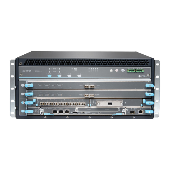
The SRX5400 Services Gateway is 5 rack units (U) tall. You can stack eight services gateways in a rack that is at least 48 U (89.3 in. or 2.24 m) in height if it has a 1 in. cap between for increased port density per unit of floor space. -
Page 25: Benefits Of The Srx5400 Services Gateway
Gbps IMIX firewall throughput, 90 million concurrent sessions, and 230 Gbps IPS. The ability to support unique security policies per zone with a compelling performance, makes the SRX5400 an optimal solution for the edge or data center services in large enterprise, service provider, or mobile operator environments. -
Page 26: Srx5400 Services Gateway Frus
Lost productivity and the impact of malicious URLs and extraneous or malicious content on the network to help maintain bandwidth. Advanced Threat Prevention (ATP) - Juniper Sky ATP, a SaaS-based service, and the Juniper ATP Appliance, an on-premises solution: Protects enterprise users from a spectrum of advanced malware that exploits “zero-day” vulnerabilities. -
Page 27: Srx5400 Services Gateway Component Redundancy
SPCs MPCs MICs SRX5400 Services Gateway Component Redundancy The following major hardware components are redundant: Power supplies—The services gateway is configurable with two or three AC power supplies at the rear of the chassis in slots PEM0 through PEM3 (left to right)or two DC power supplies in slots PEM0 and PEM2. -
Page 28: Srx5400 Chassis
SRX5400 Services Gateway Midplane Description | 32 SRX5400 Services Gateway Craft Interface Overview | 33 SRX5400 Services Gateway Craft Interface Alarm LEDs and Alarm Cutoff/Lamp Test Button | 34 SRX5400 Services Gateway Craft Interface Host Subsystem LEDs | 35 SRX5400 Services Gateway Craft Interface Power Supply LEDs | 35... - Page 29 WARNING: The services gateway must be connected to earth ground during normal operation. Figure 1: Front View of a Fully Configured Services Gateway Chassis SPCs Figure 2: Rear View of an AC-Powered Services Gateway Chassis Protective earthing AC Power supplies Power supply exhaust...
-
Page 30: Srx5400 Services Gateway Physical Specifications
FA N T R AY Air filter ESD point Fan tray Air exhaust SRX5400 Services Gateway Physical Specifications Table 4 on page 31 summarizes the physical specifications for the services gateway chassis. Table 4: Physical Specifications Description Value Chassis dimensions 8.7 in. -
Page 31: Srx5400 Services Gateway Midplane Description
High-capacity AC power supply weight 6.6 lb (3.0 kg) SRX5400 Services Gateway Midplane Description The midplane is located toward the rear of the chassis and forms the rear of the card cage. MPCs, SPCs, and SCB install into the midplane from the front of the chassis, and the power supplies install into the midplane from the rear of the chassis. -
Page 32: Srx5400 Services Gateway Craft Interface Overview
SRX5400 Services Gateway Craft Interface Overview The craft interface shows you status and troubleshooting information at a glance and lets you perform many system control functions. It is hot-insertable and hot-removable. The craft interface is located on the front of the services gateway above the upper fan tray. -
Page 33: Srx5400 Services Gateway Craft Interface Alarm Leds And Alarm Cutoff/Lamp Test Button
NOTE: The SCB must be installed in the services gateway for the craft interface to obtain power. SRX5400 Services Gateway Craft Interface Alarm LEDs and Alarm Cutoff/Lamp Test Button Two large alarm LEDs are located at the upper right of the craft interface. The circular red LED lights to indicate a major alarm condition that can result in a system shutdown. -
Page 34: Srx5400 Services Gateway Craft Interface Host Subsystem Leds
Causes all LEDs on the craft interface to light (for testing) when pressed and held. SRX5400 Services Gateway Craft Interface Host Subsystem LEDs The host subsystem has three LEDs, located on the upper left of the craft interface, that indicate its status. -
Page 35: Srx5400 Services Gateway Craft Interface Card Ok/Fail Leds
On steadily Power supply has failed or power input has failed. SRX5400 Services Gateway Craft Interface Card OK/Fail LEDs Each slot in the card cage has a pair of LEDs on the craft interface that indicates the status of the card installed in it. -
Page 36: Srx5400 Services Gateway Craft Interface Online/Offline Buttons
SRX5400 Services Gateway Craft Interface Online/Offline Buttons The craft interface has a row of Online/Offline buttons along its lower edge. Each button corresponds to one slot in the card cage. The Online/Offline buttons are only supported for slots containing MPC interface cards. - Page 37 node0: -------------------------------------------------------------------------- Offline initiated, use "show chassis fpc" to verify {primary:node0} user@host> show chassis fpc node0: -------------------------------------------------------------------------- Temp CPU Utilization (%) Memory Utilization (%) Slot State Total Interrupt DRAM (MB) Heap Buffer Online 1024 Online 1024 Offline ---Offlined by cli command--- After pushing MPC online button: user@host>...
-
Page 38: Srx5400 Services Gateway Craft Interface Alarm Relay Contacts
1024 Online 1024 SRX5400 Services Gateway Craft Interface Alarm Relay Contacts The craft interface has two alarm relay contacts for connecting the device to external alarm devices (see Figure 5 on page 40). Whenever a system condition triggers either the major or minor alarm on the craft... - Page 39 interface, the alarm relay contacts are also activated. The alarm relay contacts are located on the upper right of the craft interface. Figure 5: Alarm Relay Contacts The alarm relay contacts consist of two sets of connectors, one set for each of the two alarms (major and minor).
-
Page 40: Srx5400 Cooling System
Figure 6: Example Alarm Reporting Device RELATED DOCUMENTATION General Electrical Safety Guidelines and Warnings Preventing Electrostatic Discharge Damage to the SRX5400 Services Gateway SRX5400 Cooling System The cooling system consists of the following components: Fan tray Air filter The cooling system components work together to keep all services gateway components within the... - Page 41 Figure 7: Airflow Through the Chassis The host subsystem monitors the temperature of the services gateway components. When the device is operating normally, the fans function at lower than full speed. If a fan fails or the ambient temperature rises above a threshold, the speed of the remaining fans is automatically adjusted to keep the temperature within the acceptable range.
-
Page 42: Srx5400 Power System
SRX5400 Services Gateway AC Power Supply LEDs | 47 AC Power Cord Specifications for the SRX5400 Services Gateway | 48 AC Power Circuit Breaker Requirements for the SRX5400 Services Gateway | 51 SRX5400 Services Gateway DC Power Supply | 51... -
Page 43: Srx5400 Services Gateway Power System Overview
DC Power Cable Lug Specifications for the SRX5400 Services Gateway | 54 DC Power Circuit Breaker Requirements for the SRX5400 Services Gateway | 55 DC Power Source Cabling for the SRX5400 Services Gateway | 55 SRX5400 Services Gateway Chassis Grounding Point Specifications | 56... - Page 44 Services Gateway AC Power Supply Specifications” on page 46 “SRX5400 Services Gateway DC Power Supply Specifications” on page Table 13: Power Supply Type Summary Power Supply Type Input Condition (If Any) Maximum Output Redundancy Low-line (110 V Input) 1167 W...
-
Page 45: Srx5400 Services Gateway Ac Power Supply
This separate protective earthing terminal must be permanently connected to earth. NOTE: The SRX5400 Services Gateway and SRX5600 Services Gateway use the same power supply model. SRX5400 Services Gateway AC Power Supply Specifications Table 15 on page 47 lists the AC power supply electrical specifications. -
Page 46: Srx5400 Services Gateway Ac Power Supply Leds
Output power (maximum) per system 3501 W 4100 W SRX5400 Services Gateway AC Power Supply LEDs Each AC power supply faceplate contains three LEDs that indicate the status of the power supply (see Table 17 on page 48). The power supply status is also reflected in two LEDs on the craft interface. In... -
Page 47: Ac Power Cord Specifications For The Srx5400 Services Gateway
Check AC OK and DC OK LEDs for more information. AC Power Cord Specifications for the SRX5400 Services Gateway Each AC power supply has a single AC appliance inlet located on the power supply that requires a dedicated AC power feed. - Page 48 Table 18: AC Power Cord Specifications Electrical Country Model Number Specification Plug Type Graphic Australia CBL-M-PWR-RA-AU 240 VAC, 50 Hz AC SAA/3/15 China CBL-M-PWR-RA-CH 220 VAC, 50 Hz AC CH2-16P Europe CBL-M-PWR-RA-EU 220 or 230 VAC, CEE 7/7 (except 50 Hz AC Denmark, Italy, Switzerland,...
- Page 49 To meet safety and electromagnetic interference (EMI) requirements and to ensure proper operation, you must properly ground the services gateway chassis before connecting power. See “Grounding the SRX5400 Services Gateway” on page 199 for instructions. CAUTION: Power cords and cables must not block access to device components or...
-
Page 50: Ac Power Circuit Breaker Requirements For The Srx5400 Services Gateway
We recommend that you provision 60 A or 70 A per feed, depending on the selected DIP switch setting. Figure 11: DC Power Supply Faceplate NOTE: The SRX5400 Services Gateway and SRX5600 Services Gateway use the same power supply model. -
Page 51: Srx5400 Services Gateway Dc Power Supply Specifications
SRX5400 Services Gateway DC Power Supply Specifications Table 19 on page 52 lists the DC power supply electrical specifications. Table 20 on page 52 lists the DC power system specifications. Table 19: DC Power Supply Electrical Specifications Specification Item DIP=0 (60 A Input) -
Page 52: Dc Power Cable Specifications For The Srx5400 Services Gateway
DC input is present, but not in valid operating range or connected in reverse polarity. DC Power Cable Specifications for the SRX5400 Services Gateway Table 22 on page 53 summarizes the specifications for the power cables, which you must supply. -
Page 53: Dc Power Cable Lug Specifications For The Srx5400 Services Gateway
DC power source at your site determines the color coding for the leads on the power cables that attach to the terminal studs on each power supply. DC Power Cable Lug Specifications for the SRX5400 Services Gateway The accessory box shipped with the services gateway includes the cable lugs that attach to the terminal... -
Page 54: Dc Power Circuit Breaker Requirements For The Srx5400 Services Gateway
DC Power Circuit Breaker Requirements for the SRX5400 Services Gateway Each DC power supply has a single DC input (–48 VDC and return) that requires a dedicated facility circuit breaker. We recommend that you use a customer site circuit breaker rated for 40 A (–48 VDC) minimum for each DC power supply, or as required by local code. -
Page 55: Srx5400 Services Gateway Chassis Grounding Point Specifications
To meet safety and electromagnetic interference (EMI) requirements and to ensure proper operation, you must properly ground the services gateway chassis before connecting power. See “Grounding the SRX5400 Services Gateway” on page 199 for instructions. CAUTION: Before services gateway installation begins, a licensed electrician must attach cable lugs to the grounding and power cables that you supply. -
Page 56: Srx5400 Services Gateway Grounding-Cable Specification
), minimum 60°C wire, or as required by the local code WARNING: To meet safety and electromagnetic interference (EMI) requirements and to ensure proper operation, you must properly ground the services gateway chassis before connecting power. See “Grounding the SRX5400 Services Gateway” on page 199 for instructions. -
Page 57: Srx5400 Services Gateway Grounding-Cable Lug Specification
The same cable lug is used for the DC power cables. RELATED DOCUMENTATION Calculating Power Requirements for the SRX5400 Services Gateway | 154 Removing an SRX5400 Services Gateway DC Power Supply | 237 Replacing an SRX5400 Services Gateway AC Power Supply | 234... -
Page 58: Srx5400 Host Subsystem
SRX5400 Host Subsystem IN THIS SECTION SRX5400 Services Gateway Host Subsystem Overview | 59 Switch Control Board SRX5K-SCB Overview | 60 Switch Control Board SRX5K-SCB Specifications | 61 Switch Control Board SRX5K-SCBE Overview | 64 Switch Control Board SRX5K-SCBE Specifications | 65... -
Page 59: Switch Control Board Srx5K-Scb Overview
SRX5K-RE-13-20–from Junos OS Release 9.2 to 12.3X48 SRX5K-RE-1800X4–from Junos OS Release 12.1X47-D15 and later SRX5K-RE3-128G–from Junos OS Release 19.3R1 and later NOTE: You can only configure the following combination of Routing Engine and SCB within a host subsystem: SRX5K-RE-13-20 and SRX5K-SCB SRX5K-RE-1800X4 and SRX5K-SCBE SRX5K-RE-1800X4 and SRX5K-SCB3 SRX5K-RE-1800X4 and SRX5K-SCB4... -
Page 60: Switch Control Board Srx5K-Scb Specifications
Provides interconnections to all the IOCs within the chassis through the switch fabrics integrated into the SCB SRX5400 and SRX5600 Services Gateways have one SCB each installed and you can install a second SCB for redundancy. The SRX5800 Services Gateway has two SCBs installed and you can install a third SCB... - Page 61 The host subsystem is composed of a Routing Engine installed directly into a slot on the faceplate of the SCB. When there is no Routing Engine is a SCB, its slot must be covered with a blank panel. Figure 17: Switch Control Board SRX5K-SCB Each SCB consists of the following components: Chassis management Ethernet switch.
- Page 62 Cables and connectors Slot for Routing Engine Controls None Supported Slots SRX5400–Only bottom slots 0 and 1/0 SRX5600–Only bottom slots 0 and 1 SRX5800–Only center slots 0, 1, and 2/6 Power Requirement 150 W Weight Approximately 10 lb (4.5 kg)
-
Page 63: Switch Control Board Srx5K-Scbe Overview
Serial Number Location The serial number label is located as shown in Figure 18 on page Figure 18: SCB Serial Number Label Serial number ID label Switch Control Board SRX5K-SCBE Overview The SRX5000 line enhanced Switch Control Board (SRX5K-SCBE) caters to high-end security markets requiring support for higher capacity traffic. -
Page 64: Switch Control Board Srx5K-Scbe Specifications
Figure 19: SRX5K-SCBE Switch Control Board SRX5K-SCBE Specifications Each SRX5K-SCBE consists of the following components: I2C bus logic for low-level communication with each component Component redundancy circuitry Control Board/Routing Engine mastership mechanism Gigabit Ethernet switch that is connected to the embedded CPU complex on all components Switch fabric to provide the switching functions for the MPCs 1000BASE-T Ethernet controller to provide a 1-Gbps Ethernet link between the Routing Engines... - Page 65 Cables and connectors Slot for Routing Engine Controls None Supported slots SRX5400–Only bottom slots 0 and 1/0 SRX5600–Only bottom slots 0 and 1 SRX5800–Only center slots 0, 1, and 2/6 Power requirement 160 W at 131º F (55º C) 130 W at 104º F (40º C) 120 W at 77º...
-
Page 66: Srx5K-Scbe Leds
Serial number location The serial number label is located as shown in Figure 20 on page Figure 20: SRX5K-SCBE Serial Number Label Serial number ID label SRX5K-SCBE LEDs Table 24 on page 67 describes the SRX5K-SCBE LEDs and their states. Table 24: SRX5K-SCBE LEDs Label Color... -
Page 67: Switch Control Board Srx5K-Scb3 Overview
The SRX5K-SCB3 (SCB3) caters to high-end security markets requiring support for higher capacity traffic, greater interface density (slot and capacity scale), and improved services. The SCB3 is supported on SRX5400, SRX5600, and SRX5800 Services Gateways. The SCB3 supports the standard midplane and the enhanced midplane. -
Page 68: Switch Control Board Srx5K-Scb3 Specifications
Junos OS Release 15.1X49-D10 and later Cables and connectors Slot for Routing Engine Controls None Supported slots SRX5400–Only bottom slots 0 and 1/0 SRX5600–Only bottom slots 0 and 1 SRX5800–Only center slots 0, 1, and 2/6 Power requirement 300 W Weight... -
Page 69: Srx5K-Scb3 Leds
Serial number location The serial number label is located as shown in Figure 22 on page Figure 22: SRX5K-SCB3 Serial Number Label SRX5K-SCB3 LEDs Table 25 on page 70 describes the SCB3 LEDs and their states. Table 25: SRX5K-SCB3 LEDs Label Color State... -
Page 70: Routing Engine Srx5K-Re-13-20 Specifications
Figure 23: SRX5K-RE-13-20 Routing Engine For detailed information about the Routing Engines supported by the services gateway, see the SRX5400, SRX5600, and SRX5800 Services Gateway Card Reference at www.juniper.net/documentation/. Routing Engine SRX5K-RE-13-20 Specifications The SRX5K-RE-13-20 Routing Engine (Figure 24 on page 71) is an Intel-based PC platform that runs the Junos operating system (Junos OS). - Page 71 For specific information about Routing Engine components (for example, the amount of DRAM), issue the show chassis routing-engine command. Description Routing Engine for SRX5400, SRX5600, and SRX5800 Services Gateways Software release Junos OS Release 9.2 and later Junos OS Release 10.0 and later required to install a second Routing Engine...
- Page 72 MASTER LED: Blue–The Routing Engine is Primary. NOTE: The SRX5400, SRX5600, and SRX5800 Services Gateways do not support a secondary or backup Routing Engine, so the MASTER LED should always be lit. OK/FAIL LED, one bicolor: Off–The Routing Engine is operating normally.
-
Page 73: Routing Engine Srx5K-Re-1800X4 Overview
Serial Number The serial number label is located on the right side of the top of the Routing Engine as shown Location Figure 25 on page 74 Figure 25: SRX5K-RE-13-20 Serial Number Label Routing Engine SRX5K-RE-1800X4 Overview The enhanced Routing Engine is an Intel-based PC platform that runs Junos OS. Software processes that run on the Routing Engine maintain the routing tables, manage the routing protocols used on the device, control the device interfaces, control some chassis components, and provide the interface for system management and user access to the device.The Routing Engine must be installed directly into the... -
Page 74: Srx5K-Re-1800X4 Routing Engine Boot Sequence
The ports function as follows: AUX–Connects the Routing Engine to a laptop, modem, or other auxiliary device through a serial cable with an RJ-45 connector. CONSOLE–Connects the Routing Engine to a system console through a serial cable with an RJ-45 connector. - Page 75 Online/Offline button—Takes the Routing Engine online or offline when pressed. Extractor clips—Inserts and extracts the Routing Engine. Captive screws—Secures the Routing Engine in place. Description Routing Engine for SRX5400, SRX5600, and SRX5800 Services Gateways Software release Junos OS Release 12.1X47-D15 and later Cables and connectors Slot for Routing Engine AUX–Connects the Routing Engine to a laptop, a modem, or another auxiliary...
-
Page 76: Srx5K-Re-1800X4 Leds
Serial number location The serial number label is located as shown in Figure 27 on page Figure 27: SRX5K-RE-1800X4 Serial Number Label SRX5K-RE-1800X4 LEDs Each Routing Engine has four LEDs that indicate its status. The LEDs, labeled MASTER, STORAGE, ONLINE, and OK/FAIL, are located directly on the faceplate of the Routing Engine. -
Page 77: Routing Engine Srx5K-Re3-128G Specifications
MASTER Description Routing Engine for SRX5400, SRX5600, and SRX5800 Services Gateways, based on Intel’s Haswell-EP CPU with 6 cores, and 128GB of DDR4 memory. It provides increased control plane performance and scalability along with virtualization features in the SRX Series 5000 line of chassis. - Page 78 Controls RESET button–Reboots the Routing Engine when pressed. Supported slots Front panel slot in an SCB installed in: SRX5400: Bottom slot 0 SRX5600: Bottom slots 0 or 1 SRX5800: Center slots 0 or 1 NOTE: The services gateway host subsystem Routing Engine must be installed in the SCB in slot 0.
-
Page 79: Srx5K-Re3-128G Routing Engine Components
Serial number location The serial number label is located as shown in Figure 29 on page Figure 29: SRX5K-RE3-128G Serial Number Label Serial number ID label SRX5K-RE3-128G Routing Engine Components Each Routing Engine consists of the following components: CPU—Runs Junos OS to maintain the routing tables and routing protocols. EEPROM—Stores the serial number of the Routing Engine. -
Page 80: Srx5K-Re3-128G Routing Engine Leds
NOTE: The control interface names differ based on the routing engine: For RE2, the control interfaces are displayed as em0 and em1. For RE3, the control interfaces are displayed as ixlv0 and igb0. For more information, see show chassis cluster interfaces. Status LEDs—Table 27 on page 81 describes the functions of the ONLINE, OK/FAIL, MASTER, DISK1,... -
Page 81: Srx5K-Re3-128G Routing Engine Boot Sequence
LAN. SSD1 is the primary boot device. The boot sequence is tried twice for SSD1 and SSD2. RELATED DOCUMENTATION Replacing the SRX5400 Services Gateway SCB | 248 Maintaining the SRX5400 Services Gateway Host Subsystem | 245 Replacing the SRX5400 Services Gateway Routing Engine | 251 Replacing a CompactFlash Card in an SRX5K-RE-1800X4 Routing Engine... -
Page 82: Srx5400 Line Cards And Modules
IN THIS SECTION SRX5400, SRX5600, and SRX5800 Services Gateway Card Overview | 84 Cards Supported on SRX5400, SRX5600, and SRX5800 Services Gateways | 85 SRX5400 Services Gateway Card Cage and Slots | 88 SRX5400 Services Gateway Services Processing Card Overview | 89... -
Page 83: Srx5400, Srx5600, And Srx5800 Services Gateway Card Overview
SRX5400, SRX5600, and SRX5800 Services Gateway Card Overview The cards described in this guide let you upgrade and customize your SRX5400, SRX5600, or SRX5800 Services Gateway to suit the needs of your network. The following types of cards are available for the SRX5400, SRX5600, and SRX5800 Services Gateways: I/O cards (IOCs) provide additional physical network connections to the services gateway. -
Page 84: Cards Supported On Srx5400, Srx5600, And Srx5800 Services Gateways
Cards Supported on SRX5400, SRX5600, and SRX5800 Services Gateways Table 28 on page 85 describes the cards and other modules supported on the SRX5400, SRX5600, and SRX5800 Services Gateways. Table 28: Supported Cards for SRX5400, SRX5600, and SRX5800 Services Gateways... - Page 85 Table 28: Supported Cards for SRX5400, SRX5600, and SRX5800 Services Gateways (continued) Last Supported Junos Earliest Supported Junos OS Release OS Release Card Name and Model SRX5400, SRX5600, Number SRX5400 SRX5600 and SRX5800 and SRX5800 SRX5K-IOC4-10G Specifications 19.3R1 19.3R1 SRX5K-IOC4-MRAT 19.3R1...
- Page 86 Table 28: Supported Cards for SRX5400, SRX5600, and SRX5800 Services Gateways (continued) Last Supported Junos Earliest Supported Junos OS Release OS Release Card Name and Model SRX5400, SRX5600, Number SRX5400 SRX5600 and SRX5800 and SRX5800 MIC with 2x40GE QSFP+ 12.1X46-D10 12.1X46-D10...
-
Page 87: Srx5400 Services Gateway Card Cage And Slots
Figure 30: Interoperability Matrix for SRX5400, SRX5600, and SRX5800 Services Gateways Model Numbers SRX5400 SRX5K-SCB SRX5K-RE-13-20 SRX5600/SRX5800 SRX5K-SCB SRX5K-RE-13-20 SRX5K-SCBE SRX5K-RE-1800X4 SRX5K-SCB3 SRX5K-RE-1800X4 SRX5K-SPC-2-10-40 SRX5K-SPC-4-15-320 SRX5K-SPC3 SRX5K-4XGE-XFP SRX5K-40GE-SFP SRX5K-FPC-IOC SRX5K-MPC (SRX-MIC-20GE-SFP) (SRX-MIC-10XG-SFPP) (SRX-MIC-1X100G-CFP) (SRX-MIC-2X40G-QSFP) SRX5K-MPC3-40G10G SRX5K-MPC3-100G10G SRX5K-IOC4-10G SRX5K-IOC4-MRAT SRX5600/SRX5800 SRX5K-SCB4... -
Page 88: Srx5400 Services Gateway Services Processing Card Overview
Table 29: SRX5400 Services Gateway Card Cage Slots (continued) Eligible Cards Card Cage Slot MPC & IOC SEE ALSO SRX5400 Services Gateway Midplane Description | 32 SRX5400 Services Gateway Chassis | 29 SRX5400 Services Gateway Services Processing Card Overview The Services Processing Card (SPC) has Services Processing Units (SPUs), which provide the processing... -
Page 89: Services Processing Card Srx5K-Spc-2-10-40 Specifications
Figure 31: Typical SPC For detailed information about SPCs supported by the services gateway, see the SRX5400, SRX5600, and SRX5800 Services Gateway Card Reference at www.juniper.net/documentation/. Services Processing Card SRX5K-SPC-2-10-40 Specifications The SRX5K-SPC-2-10-40 Services Processing Card (SPC) contains two Services Processing Units (SPUs),... - Page 90 Your JTAC engineer might recommend that you check the third-party optic or cable and potentially replace it with an equivalent Juniper Networks optic or cable that is qualified for the device. Fabric interfaces.
- Page 91 Processor subsystem, which includes a 1.2-GHz CPU, system controller, and 1 GB of SDRAM. LEDs on the faceplate that indicate the SPC and SPU status. Description SPC with two SPUs Software release Junos OS Release 9.2 and later Cables and CHASSIS CLUSTER CONTROL 0 and CHASSIS CLUSTER CONTROL 1–SFP ports for control connectors links in chassis cluster configurations.
- Page 92 LEDs OK/FAIL LED, one bicolor: Steady green–The SPC is operating normally. Red–The SPC has failed and is not operating normally. Off–The SPC is powered down. STATUS LED, one tricolor for each of the two SPUs SPU 0 and SPU 1: Green–The SPU is operating normally.
-
Page 93: Services Processing Card Srx5K-Spc-4-15-320 Specifications
Serial Number The serial number label is located as shown in Figure 33 on page Location Figure 33: Serial Number Label (IOC Shown, Other Cards Similar) OK /F AIL Serial number ID label AA567 8 Services Processing Card SRX5K-SPC-4-15-320 Specifications The SRX5K-SPC-4-15-320 Services Processing Card (SPC) contains four Services Processing Units (SPUs), which provide the processing power to run integrated services such as firewall, IPsec, and IDP (see Figure 34 on page... - Page 94 Your JTAC engineer might recommend that you check the third-party optic or cable and potentially replace it with an equivalent Juniper Networks optic or cable that is qualified for the device. Fabric interfaces.
- Page 95 None Supported Slots SRX5400–Any slot, except the bottom slot 0 which is reserved for SCB/RE. SRX5600–Any slot, except the bottom slots 0 or 1 which are reserved for SCB/RE. SRX5800–Any slot, except the slots 0 or 1 which are reserved for SCB/RE.
- Page 96 LEDs...
- Page 97 OK/FAIL LED, one bicolor: Steady green–The SPC is operating normally. Red–The SPC has failed and is not operating normally. Off–The SPC is powered down. STATUS LED, one tricolor for each of the four SPUs SPU 0 through SPU 3: Green–The SPU is operating normally. Amber–The SPU is initializing.
-
Page 98: Services Processing Card Srx5K-Spc3 Specifications
Off–The chassis cluster control port is disabled. Serial Number The serial number label is located as shown in Figure 35 on page Location Figure 35: Serial Number Label (IOC Shown, Other Cards Similar) OK /F AIL Serial number ID label AA567 8 Services Processing Card SRX5K-SPC3 Specifications The SRX5K-SPC3 Services Processing Card (SPC) contains two Services Processing Units (SPUs) with... - Page 99 Your JTAC engineer might recommend that you check the third-party optic or cable and potentially replace it with an equivalent Juniper Networks optic or cable that is qualified for the device. Fabric interfaces One Gigabit Ethernet switch that provides control connectivity to the Routing Engine.
- Page 100 None Supported Slots SRX5400–Any slot, except the bottom slot 0 which is reserved for SCB/RE. SRX5600–Any slot, except the bottom slots 0 or 1 which are reserved for SCB/RE. SRX5800–Any slot, except slot 11, and the slots 0 or 1 which are reserved for SCB/RE.
- Page 101 LEDs OK/FAIL LED, one bicolor: Steady green–The SPC is operating normally. Red–The SPC has failed and is not operating normally. Off–The SPC is powered down. STATUS LED, one tricolor for each SPU SPU 0 and SPU 1: Off–The SPU is offline. Blinking Amber–The SPU is initializing.
-
Page 102: Srx5400 Services Gateway Mpc And Mic Overview
2 at the bottom of the card cage. You cannot install the MPC into the SCB slot (0). NOTE: The SRX5400 Services Gateway does not support the I/O cards (IOCs) or Flex IOCs supported by the SRX5600 and SRX5800 Services Gateways. MPCs are the only supported interface cards for the SRX5400 Services Gateway. -
Page 103: Modular Port Concentrator (Srx5K-Mpc) Specifications
You can install MPCs in any of the slots that are not reserved for Switch Control Boards (SCBs). If a slot in the SRX5400, SRX5600, or SRX5800 Services Gateway card cage is not occupied by a card, you must install a blank panel to shield the empty slot and to allow cooling air to circulate properly through the services gateway. - Page 104 CLI command: user@host set security forwarding-process application-services session-distribution-mode hash-based When installing an SRX5K-MPC in an SRX5400 Services Gateway, the session-distribution-mode will only function when hash-based mode is configured or set as the default. The normal mode is not supported.
-
Page 105: Srx5K-Mpc3-40G10G Specifications
To install and use SRX5K-MPCs in the SRX5600 and SRX5800 Services Gateways, you must have high-capacity power supplies (either AC or DC) and high-capacity fan trays installed in the services gateways. All models of SRX5400 Services Gateways already include high-capacity supplies. If you do not have high-capacity power supplies and fan trays installed, the services gateway will log an alarm condition when it recognizes the SRX5K-MPCs. - Page 106 Figure 39: SRX5K-MPC3-40G10G If a slot in the SRX5400, SRX5600, or SRX5800 Services Gateway card cage is not occupied by a card, you must install a blank panel to shield the empty slot and to allow cooling air to circulate properly through the services gateway.
- Page 107 Hardware features Line-rate throughput of up to 240 Gbps Supports up to 32,000 queues per-slot LAN-PHY mode at 10.3125 Gbps on a per-port basis The ports are labeled as: 10-Gigabit Ethernet ports: 0/0 through 0/11 and 1/0 through 1/11 40-Gigabit Ethernet ports: 2/0 through 2/2 and 3/0 through 3/2 Software features Optical diagnostics and related alarms Two packet-forwarding engines, PFE0 and PFE1.
-
Page 108: Srx5K-Mpc3-100G10G Specifications
The SRX5K-MPC3-100G10G (IOC3) is an interface card that provides 100 Gigabit Ethernet and 10 Gigabit Ethernet interfaces, with a Packet Forwarding Engine that provides a 240 Gbps line rate. This interface card is supported on SRX5400, SRX5600, and SRX5800 Services Gateways. See Figure 41 on page 110. - Page 109 Figure 41: SRX5K-MPC3-100G10G If a slot in the SRX5400, SRX5600, or SRX5800 Services Gateway card cage is not occupied by a card, you must install a blank panel to shield the empty slot and to allow cooling air to circulate properly through the services gateway.
- Page 110 Hardware features Line-rate throughput of up to 240 Gbps Supports up to 32,000 queues per-slot LAN-PHY mode at 10.3125 Gbps on a per-port basis The ports are labeled as: 10-Gigabit Ethernet ports: 0/0, 0/1, 2/0, and 2/1 100-Gigabit Ethernet ports: 1/0 and 3/0 Software features Configurable LAN-PHY mode options per 10-Gigabit Ethernet port Optical diagnostics and related alarms...
-
Page 111: Mic With 20X1Ge Sfp Interfaces (Srx-Mic-20Ge-Sfp)
Serial Number Location The serial number label is located as shown in Figure 42 on page 112. Figure 42: SRX5K-MPC3-100G10G Serial Number Label MIC with 20x1GE SFP Interfaces (SRX-MIC-20GE-SFP) You use Modular Interface Cards (MICs) and Modular Port Concentrators (MPCs) to add different combinations of Ethernet interfaces to your services gateway to suit the specific needs of your network. - Page 112 Figure 43: SRX-MIC-20GE-SFP Description MIC with twenty 1-Gigabit Ethernet SFP Ethernet ports Fits into either of the two slots of SRX-5K-MPC Supports up to 20 Gbps of full-duplex traffic Maximum configurable MTU: 9192 bytes Maximum throughput: 20 Gbps Software release Junos OS Release 12.1X47-D10 Cables and connectors Sockets for 20 SFP Gigabit Ethernet transceivers.
- Page 113 Port and Interface Numbering...
- Page 114 2 or 3 when installed in the second slot. port—Port number. Figure 44 on page 115 shows the SRX-MIC-20GE-SFP MIC installed in slot 0 of an MPC in slot 2 of an SRX5400, SRX5600, or SRX5800 Services Gateway. Figure 44: SRX-MIC-20GE-SFP Interface Port Mapping SRX-MIC-20GE-SFP...
- Page 115 The sample output of the show chassis fpc pic-status command output displays two 20-port Gigabit Ethernet MICs with SFP — inserted into the slots of an MPC in slot 2. The logical PICs of the two MICs— 10x 1GE(LAN) SFP — are shown as PIC 0, PIC 1, PIC 2, and PIC 3.
- Page 116 user@host> show interfaces terse Interface Admin Link Proto Local Remote gr-0/0/0 ip-0/0/0 lt-0/0/0 ge-2/0/0 ge-2/0/1 down ge-2/0/2 down ge-2/0/3 down ge-2/0/4 down ge-2/0/5 ge-2/0/6 down ge-2/0/7 down ge-2/0/8 ge-2/0/9 ge-2/1/0 down ge-2/1/1 ge-2/1/2 down ge-2/1/3 down ge-2/1/4 ge-2/1/5 down ge-2/1/6 down ge-2/1/7 down...
-
Page 117: Mic With 10X10Ge Sfp+ Interfaces (Srx-Mic-10Xg-Sfpp)
ge-2/3/9 down Serial number location The serial number label is yellow and is located as shown in Figure 45 on page 118. Figure 45: SRX-MIC-20GE-SFP Serial Number Label NOTE: The serial number for the mezzanine card is shown only for reference and is never used for any purpose. - Page 118 Figure 46: SRX-MIC-10XG SFPP Description MIC with ten SFP+ 10-Gigabit Ethernet ports Fits into MPC Supports up to 100 Gbps of full-duplex traffic Maximum configurable MTU: 9192 bytes Maximum throughput: 100 Gbps Software Junos OS Release 12.1X46-D10 release Cables and Sockets for ten 10-Gbps SFP+ transceivers connectors Hardware Compatibility Tool...
- Page 119 Port and Interface Numbering...
- Page 120 Figure 47 on page 121 shows the port and interface numbering of an SRX-MIC-10XG-SFPP MIC when it is installed in slot 0 of an MPC in slot 2 of an SRX5400, SRX5600, or SRX5800 Services Gateway. Figure 47: SRX-MIC-10XG-SFPP Port and Interface Numbering...
- Page 121 PIC 1 Online SPU Flow PIC 2 Online SPU Flow PIC 3 Online SPU Flow Slot 2 Online SRX5k IOC II PIC 0 Online 10x 10GE SFP+ PIC 2 Online 10x 10GE SFP+ The show interfaces terse command output displays the 10–Gigabit Ethernet interfaces that correspond to the 10 ports located on each MIC.
-
Page 122: Mic With 1X100Ge Cfp Interface (Srx-Mic-1X100G-Cfp)
Serial number The serial number label is yellow and located as shown in Figure 48 on page 123. location Figure 48: SRX-MIC-10XG-SFPP Serial Number Label MIC with 1x100GE CFP Interface (SRX-MIC-1X100G-CFP) You use MICs and MPCs to add different combinations of Ethernet interfaces to your services gateway to suit the specific needs of your network. - Page 123 Software release Junos OS Release 12.1X46-D10 Cables and connectors One socket for a 100-Gigabit CFP transceiver. Supported CFP transceivers: 100GBASE-LR4 (model number: SRX-CFP-100G-LR4) 100GBASE-SR10 (model number: SRX-CFP-100G-SR10) Supported slots Either slot in SRX5K-MPC Weight Approximately 1.6 lb (0.7 kg) LEDs OK/FAIL LED, one bicolor: Green–The MIC is operating normally.
-
Page 124: Mic With 2X40Ge Qsfp+ Interfaces (Srx-Mic-2X40G-Qsfp)
MIC with 2x40GE QSFP+ Interfaces (SRX-MIC-2X40G-QSFP) You use MICs and MPCs to add different combinations of Ethernet interfaces to your services gateway to suit the specific needs of your network. The SRX-MIC-2X40G-QSFP (see Figure 51 on page 125) can be installed in an MPC to add two 40-Gigabit quad small form-factor pluggable (QSFP+) Ethernet ports. -
Page 125: I/O Card Srx5K-40Ge-Sfp Specifications
Serial number location The serial number label is yellow and typically located as shown in Figure 52 on page 126. Figure 52: SRX-MIC-2X40G-QSFP Serial Number Label Serial number ID label I/O Card SRX5K-40GE-SFP Specifications The SRX5K-40GE-SFP I/O card (IOC) is optimized for Ethernet density and supports 40 Gigabit Ethernet ports (see Figure 53 on page 127). - Page 126 Figure 53: IOC SRX5K-40GE-SFP OK / F AIL 0/0 0/5 2/0 2/5 1/0 1/5 3/0 3/5 Description I/O card with 40 Gigabit Ethernet SFP ports Maximum configurable MTU: 9192 bytes Maximum throughput: 40 Gbps Software release Junos OS Release 9.2 and later Cables and connectors 40 Gigabit Ethernet SFP ports Supported SFP transceivers:...
-
Page 127: I/O Card Srx5K-4Xge-Xfp Specifications
LEDs OK/FAIL LED, one bicolor: Steady green–The IOC is operating normally. Red–The IOC has failed and is not operating normally. Off–The IOC is powered down. Serial Number Location The serial number label is located as shown in Figure 54 on page 128. - Page 128 Figure 55: IOC SRX5K-4XGE-XFP OK /FA IL Description I/O card with four 10-Gigabit Ethernet XFP ports Maximum configurable MTU: 9192 bytes Maximum throughput: 40 Gbps Software release Junos OS Release 9.2 and later Cables and connectors Four 10-Gbps XFP ports Supported XFP transceivers: 10GBASE-ER (model numbers SRX-XFP-10GE-ER and SRX-XFP-10GE-ER-ET ) 10GBASE-LR (model numbers SRX-XFP-10GE-LR and SRX-XFP-10GE-LR-ET...
-
Page 129: Srx5K-Ioc4-10G Specifications
SRX5K-IOC4-10G Specifications SRX5K-IOC4-10G is a fixed-configuration interface card with a Packet Forwarding Engine that provides 400-Gbps line rate. This interface card provides scalability in bandwidth and services to the SRX5400, SRX5600 and SRX5800 Services Gateways. See Figure 57 on page 131. - Page 130 SRX5K-IOC4-10G If a slot in the SRX5400, SRX5600, or SRX5800 Services Gateway card cage is not occupied by a card, you must install a blank panel to shield the empty slot and to allow cooling air to circulate properly through the services gateway.
- Page 131 Hardware features Junos Trio chipsets for increased scaling for bandwidth, subscribers, and services Forty 10-Gigabit Ethernet ports. The ports support SFP+ transceivers. Requires high-capacity power supplies and high-capacity fan trays. The ports are labeled as (seeFigure 57 on page 131): 0/0 through 0/9 0/10 through 0/19 1/0 through 1/9...
-
Page 132: Srx5K-Ioc4-Mrat Specifications
SRX5K-IOC4-MRAT is a fixed-configuration interface card with a Packet Forwarding Engine that provides up to 480-Gbps (240-Gbps per PIC slot) line rate. This interface card provides scalability in bandwidth and services to the SRX5400, SRX5600, and SRX5800 Services Gateways. See Figure 59 on page 133. - Page 133 If a slot in the SRX5400, SRX5600, or SRX5800 Services Gateway card cage is not occupied by a card, you must install a blank panel to shield the empty slot and to allow cooling air to circulate properly through the services gateway.
- Page 134 Hardware features Junos Trio chipsets for increased scaling for bandwidth, subscribers, and services Twelve Gigabit Ethernet ports that can be configured as 40-Gigabit Ethernet port or as 4X10-Gigabit Ethernet port using a breakout cable. The ports support quad small-form factor pluggable plus (QSFP+) transceivers. Four out of the twelve ports can be configured as 100-Gigabit Ethernet ports.
- Page 135 Software features Application security Application Layer Gateway (ALG) Attack detection and prevention Class of service (CoS) Equal-cost multipath (ECMP) load balancing GPRS Tunneling Protocol (GTP) High availability (chassis cluster) Intrusion detection and prevention (IDP) IPsec VPN Layer 2 transparent mode Logical systems Network Address Translation (NAT) Routing protocols (BFD, BGP, IGMP, IS-IS, MLD,...
-
Page 136: Flex I/O Card (Srx5K-Fpc-Ioc) Specifications
Flex I/O Card (SRX5K-FPC-IOC) Specifications The SRX5K-FPC-IOC Flex I/O card (Flex IOC) (Figure 61 on page 137) is an IOC with two slots that accept port modules that add Ethernet ports to your services gateway. A Flex IOC with installed port modules functions in the same way as a regular IOC, but allows greater flexibility in adding different types of Ethernet ports to your services gateway. -
Page 137: Flex I/O Card Port Module Srx-Ioc-16Ge-Sfp Specifications
Power Requirement 312 W typical, 365 W maximum (includes port modules) Weight Approximately 10 lb (4.5 kg) LEDs OK/FAIL LED, one bicolor: Steady green–The Flex IOC is operating normally. Red–The Flex IOC has failed and is not operating normally. Off–The Flex IOC is powered down. Serial Number Location The serial number label is located as shown in Figure 62 on page... - Page 138 Figure 63: Flex IOC Port Module SRX-IOC-16GE-SFP Description Port module with 16 Gigabit Ethernet SFP ports Maximum throughput: 10 Gbps Oversubscription ratio: 1.6:1 Maximum configurable MTU: 9192 bytes Software release Junos OS Release 9.5R1 and later Cables and connectors 16 Gigabit Ethernet SFP ports Supported SFP transceivers: 1000BASE-LH (model numbers SRX-SFP-1GE-LH, SRX-SFP-1GE-LH-ET) 1000BASE-LX (model numbers SRX-SFP-1GE-LX, SRX-SFP-1GE-LX-ET)
-
Page 139: Flex I/O Card Port Module Srx-Ioc-16Ge-Tx Specifications
LEDs OK/FAIL LED, one bicolor: Steady green–The port module is operating normally. Red–The port module has failed and is not operating normally. Off–The port module is powered down. LINK LED, single color, one per port: Steady green–The link is active. Off–No link. - Page 140 Figure 65: Flex IOC Port Module SRX-IOC-16GE-TX Description Port module with sixteen 10/100/1000 Ethernet RJ45 ports Maximum throughput: 10 Gbps Oversubscription ratio: 1.6:1 Maximum configurable MTU: 9192 bytes Software release Junos OS Release 9.5R1 and later Cables and connectors Sixteen RJ-45 1-Gbps ports Controls ONLINE Button–The ONLINE button on the port module front panel toggles the port module online and offline.
-
Page 141: Flex I/O Card Port Module Srx-Ioc-4Xge-Xfp Specifications
Serial Number Location The serial number label is located as shown in Figure 66 on page 142. Figure 66: Port Module SRX-IOC-16GE-TX Serial Number Label Serial number ID label JX0123 Flex I/O Card Port Module SRX-IOC-4XGE-XFP Specifications You use port modules and Flex I/O Cards (Flex IOCs) to add different combinations of small form-factor pluggable transceiver (SFP), 10-gigabit SFP transceiver (XFP), and copper ports to your services gateway to suit the specific needs of your network. - Page 142 The serial number label is located as shown in Figure 68 on page 143. Figure 68: Port Module SRX-IOC-4XGE-XFP Serial Number Label Serial number ID label JX0123 RELATED DOCUMENTATION SRX5400 Services Gateway Chassis | 29 SRX5400 Services Gateway FRUs | 27...
- Page 143 SRX5400 Services Gateway Midplane Description | 32 Installing an SRX5400 Services Gateway SPC | 297 Maintaining SPCs on the SRX5400 Services Gateway | 293 Troubleshooting SRX5400 Services Gateway SPCs | 360 Installing an SRX5400 Services Gateway MPC | 283 Installing an SRX5400 Services Gateway MIC | 288...
-
Page 144: Site Planning, Preparation, And Specifications
C HAPTER Site Planning, Preparation, and Specifications Site Preparation Checklist for the SRX5400 Services Gateway | 147 SRX5400 Site Guidelines and Requirements | 148 SRX5400 Rack and Cabinet Requirements | 152 Calculating Power Requirements for the SRX5400 Services Gateway | 154... -
Page 146: Site Preparation Checklist For The Srx5400 Services Gateway
Site Preparation Checklist for the SRX5400 Services Gateway The checklist in Table 30 on page 147 summarizes the tasks you need to perform when preparing a site for services gateway installation. Table 30: Site Preparation Checklist Performed Item or Task For More Information ... -
Page 147: Srx5400 Site Guidelines And Requirements
SRX5400 Services Gateway Environmental Specifications | 148 General Site Guidelines | 149 Site Electrical Wiring Guidelines | 150 Clearance Requirements for SRX5400 Services Gateway Airflow and Hardware Maintenance | 151 SRX5400 Services Gateway Environmental Specifications Table 31 on page 148 specifies the environmental specifications required for normal services gateway operation. -
Page 148: General Site Guidelines
Table 31: Services Gateway Environmental Specifications (continued) Description Value Temperature Normal operation ensured in temperature range of 32°F (0°C) to 104°F (40°C) Nonoperating storage temperature in shipping container: –40°F (–40°C) to 158°F (70°C) Seismic Designed to meet Telcordia Technologies Zone 4 earthquake requirements Maximum thermal output AC power: 8065 BTU/hour (2365 W) DC power: 7325 BTU/hour (2148 W) -
Page 149: Site Electrical Wiring Guidelines
Site Electrical Wiring Guidelines Table 32 on page 150 describes the factors you must consider while planning the electrical wiring at your site. WARNING: You must provide a properly grounded and shielded environment and use electrical surge-suppression devices. Table 32: Site Electrical Wiring Guidelines Site Wiring Factor Guidelines Signaling limitations... -
Page 150: Clearance Requirements For Srx5400 Services Gateway Airflow And Hardware Maintenance
NEBS GR-63 recommends that you allow at least 30 in. (76.2 cm) in front of the services gateway. Figure 69: Chassis Dimensions and Clearance Requirements RELATED DOCUMENTATION SRX5400 Services Gateway Agency Approvals | 439 SRX5400 Services Gateway Compliance Statements for EMC Requirements | 440... -
Page 151: Srx5400 Rack And Cabinet Requirements
IN THIS SECTION SRX5400 Services Gateway Rack Size and Strength Requirements | 152 Spacing of Rack Mounting Bracket Holes for the SRX5400 Services Gateway | 153 Connection to Building Structure for the SRX5400 Services Gateway Rack | 153 SRX5400 Services Gateway Cabinet Size and Clearance Requirements | 153... -
Page 152: Spacing Of Rack Mounting Bracket Holes For The Srx5400 Services Gateway
(100 kg). If you stack five fully configured devices in one rack, it must be capable of supporting up to 1100 lb (500 kg). Spacing of Rack Mounting Bracket Holes for the SRX5400 Services Gateway The services gateway can be mounted in any rack that provides holes or hole patterns spaced at 1 U (1.75 in.) increments. -
Page 153: Srx5400 Services Gateway Cabinet Airflow Requirements
We recommend that you provision power according to the maximum input current listed in the power supply electrical specifications (see “SRX5400 Services Gateway AC Power Supply Specifications” on page 46 “SRX5400 Services Gateway DC Power Supply Specifications” on page 52). Use the following procedures to calculate the power requirement: 1. Calculate the power requirement. - Page 154 The following sample configuration shows an SRX5400 Services Gateway chassis with various power supplies and: Two SRX5K-SPC-4-15-320 (SPC2) Services Processing Card (SPC) (slots 1 and 2) One SRX5K-MPC (IOC2) with two MICs installed in it (slot 1/0) One switch control board SRX5K-SCB (SCB1) or SRX5K-SCBE (SCB2) and one Routing Engine SRX5K-RE-13-20 (RE1) or SRX5KRE-1800X4 (RE2) installed in it (SCB slot 0) 1.
- Page 155 To do this, divide the total output requirement by the efficiency of the power supply as shown in Table 36 on page 156 Here we include the power drawn by the cooling system. Table 36: Calculating System Input Power Power Supply Efficiency Power Supply Input Power Requirement SRX5400 AC 89 % 2095/0.89 = 2354 W...
- Page 156 Table 36: Calculating System Input Power (continued) Power Supply Efficiency Power Supply Input Power Requirement SRX5400 DC ~98 % 2095/0.98 = 2138 W These values are at full load and nominal voltage. 4. Calculate thermal output (BTUs) for the system. To calculate this value, multiply the total input power requirement (in watts) by 3.41 as shown in...
- Page 157 One switch control board SRX5K-SCB3 (SCB3) and one Routing Engine RE2 installed in SCB slot 0 1. Calculate the power requirements (usage) as shown in Table 38 on page 158. Table 38: Sample Power Requirements for an SRX5400 Services Gateway with SCB3, IOC3, and RE2 Chassis Component Part Number Power Requirement...
- Page 158 Here we include the power drawn by the cooling system. Table 41: Calculating System Input Power Power Supply Efficiency Power Supply Input Power Requirement SRX5400 AC 89 % 2282/0.89 = 2564 W SRX5400 DC ~98 % 2282/0.98 = 2329 W These values are at full load and nominal voltage.
-
Page 159: Srx5400 Network Cable And Transceiver Planning
Routing Engine Interface Cable and Wire Specifications for the SRX5400 Services Gateway | 160 Signal Loss in Multimode and Single-Mode Fiber-Optic Cable for the SRX5400 Services Gateway | 161 Attenuation and Dispersion in Fiber-Optic Cable for the SRX5400 Services Gateway | 161... -
Page 160: Signal Loss In Multimode And Single-Mode Fiber-Optic Cable For The Srx5400 Services Gateway
Compared with multimode fiber, single-mode fiber has higher bandwidth and can carry signals for longer distances. It is consequently more expensive. Attenuation and Dispersion in Fiber-Optic Cable for the SRX5400 Services Gateway Correct functioning of an optical data link depends on modulated light reaching the receiver with enough power to be demodulated correctly. -
Page 161: Calculating Power Budget For Fiber-Optic Cable For The Srx5400 Services Gateway
The optical power budget must allow for the sum of component attenuation, power penalties (including those from dispersion), and a safety margin for unexpected losses. Calculating Power Budget for Fiber-Optic Cable for the SRX5400 Services Gateway To ensure that fiber-optic connections have sufficient power for correct operation, you need to calculate the link's power budget, which is the maximum amount of power it can transmit. -
Page 162: Calculating Power Margin For Fiber-Optic Cable For The Srx5400 Services Gateway
Calculating Power Margin for Fiber-Optic Cable for the SRX5400 Services Gateway After calculating a link's power budget, you can calculate the power margin (P ), which represents the amount of power available after subtracting attenuation or link loss (LL) from the power budget (P ). - Page 163 RELATED DOCUMENTATION Connecting the SRX5400 Services Gateway to a Network for Out-of-Band Management | 195 Connecting the SRX5400 Services Gateway to a Management Console or an Auxiliary Device | 193...
-
Page 164: Srx5400 Alarm And Management Cable Specifications And Pinouts
RJ-45 Connector Pinouts for the SRX5400 Services Gateway Routing Engine Ethernet Port | 166 RJ-45 Connector Pinouts for the SRX5400 Services Gateway Routing Engine Auxiliary and Console Ports | 166 Alarm Relay Contact Wire Specifications for the SRX5400 Services Gateway Table 45 on page 165 lists the specifications for the wires that connect to the alarm relay contacts. -
Page 165: Connector Pinouts For The Srx5400 Services Gateway Routing Engine Ethernet Port
RJ-45 Connector Pinouts for the SRX5400 Services Gateway Routing Engine Ethernet Port The port on the Routing Engine labeled ETHERNET is an autosensing 10/100-Mbps Ethernet RJ-45 receptacle that accepts an Ethernet cable for connecting the Routing Engine to a management LAN (or other device that supports out-of-band management). - Page 166 Table 48: RJ-45 Connector Pinout for the AUX and CONSOLE Ports (continued) Signal Description Data Terminal Ready Transmit Data Ground Signal Ground Ground Signal Ground Receive Data DSR/DCD Data Set Ready Clear to Send RELATED DOCUMENTATION Connecting the SRX5400 to External Devices | 193...
-
Page 167: Initial Installation And Configuration
Installing the SRX5400 Using a Mechanical Lift | 180 Installing the SRX5400 Without a Mechanical Lift | 182 Connecting the SRX5400 to External Devices | 193 Connecting the SRX5400 to Power | 198 Performing the Initial Software Configuration for the SRX5400 | 208... -
Page 169: Srx5400 Installation Overview
193 Connecting the SRX5400 Services Gateway to a Network for Out-of-Band Management on page 195 Connecting the Alarm Relay Wires to the SRX5400 Services Gateway Craft Interface on page 226 7. Connect the grounding cable as described in “Grounding the SRX5400 Services Gateway” on page 199. -
Page 170: Unpacking The Srx5400
209. Unpacking the SRX5400 IN THIS SECTION Tools and Parts Required to Unpack the SRX5400 Services Gateway | 172 Unpacking the SRX5400 Services Gateway | 172 Verifying the SRX5400 Services Gateway Parts Received | 174 Tools and Parts Required to Unpack the SRX5400 Services Gateway... - Page 171 5. Slide the remainder of the shipping crate cover off the pallet. 6. Remove the foam covering the top of the device. 7. Remove the accessory box and the SRX5400 Services Gateway Getting Started Guide. 8. Verify the parts received as described in “Verifying the SRX5400 Services Gateway Parts Received”...
-
Page 172: Verifying The Srx5400 Services Gateway Parts Received
Figure 70: Contents of the Shipping Crate Verifying the SRX5400 Services Gateway Parts Received A packing list is included in each shipment. Check the parts in the shipment against the items on the packing list. The packing list specifies the part numbers and descriptions of each part in your order. - Page 173 RJ-45-to-DB-9 cable to connect the device through the serial port Cable manager brackets Terminal block plug, 3–pole, 5.08 mm spacing, 12A, to connect the device alarms Transceiver Label, accessories contents, SRX5400 USB flash drive with Junos OS Read me first document Affidavit for T1 connection...
-
Page 174: Installing The Srx5400 Mounting Hardware
Installing the SRX5400 Mounting Hardware IN THIS SECTION Tools and Parts Required to Install the SRX5400 Services Gateway Mounting Hardware for a Rack or Cabinet | 177 Installing the SRX5400 Services Gateway Mounting Hardware for a Rack or Cabinet | 177... -
Page 175: Tools And Parts Required To Install The Srx5400 Services Gateway Mounting Hardware For A Rack Or Cabinet
Tools and Parts Required to Install the SRX5400 Services Gateway Mounting Hardware for a Rack or Cabinet To install the services gateway in a rack or cabinet, you need the following tools: Phillips (+) screwdriver, number 2 Installing the SRX5400 Services Gateway Mounting Hardware for a Rack or Cabinet The services gateway can be installed in a four-post rack or cabinet or an open-frame rack. - Page 176 4. Partially insert the remaining screws into the open holes in each flange of the mounting shelf. 5. Tighten all the screws completely. Figure 71: Installing the Front Mounting Hardware for a Four-Post Rack or Cabinet...
-
Page 177: Moving The Mounting Brackets For Center-Mounting The Srx5400 Services Gateway
Figure 72: Installing the Mounting Hardware for an Open-Frame Rack Moving the Mounting Brackets for Center-Mounting the SRX5400 Services Gateway Two removable mounting brackets are attached to the mounting holes closest to the front of the chassis. You can move the pair of brackets to another position on the side of the chassis for center-mounting the services gateway. -
Page 178: Installing The Srx5400 Using A Mechanical Lift
Installing the SRX5400 Using a Mechanical Lift IN THIS SECTION Tools Required to Install the SRX5400 Services Gateway with a Mechanical Lift | 180 Installing the SRX5400 Services Gateway Using a Mechanical Lift | 181 Tools Required to Install the SRX5400 Services Gateway with a Mechanical... -
Page 179: Installing The Srx5400 Services Gateway Using A Mechanical Lift
Installing the SRX5400 Services Gateway Using a Mechanical Lift Because of the services gateway’s size and weight—up to 220 lb (100 kg) depending on the configuration—we strongly recommend that you install the services gateway using a mechanical lift. If you do not use a lift to install the services gateway, see “Overview of Installing the SRX5400 Services Gateway... -
Page 180: Installing The Srx5400 Without A Mechanical Lift
Overview of Installing the SRX5400 Services Gateway Without a Mechanical Lift | 183 Tools Required to Install the SRX5400 Services Gateway Without a Mechanical Lift | 183 Removing Components from the SRX5400 Chassis Before Installing It Without a Lift | 183... -
Page 181: Overview Of Installing The Srx5400 Services Gateway Without A Mechanical Lift
Installing the SRX5400 Services Gateway Chassis in the Rack Manually | 188 Reinstalling Components in the SRX5400 Services Gateway Chassis After Installing It Without a Lift | 190 Overview of Installing the SRX5400 Services Gateway Without a Mechanical Lift If you cannot use a mechanical lift to install the services gateway (the preferred method), you can install it manually. -
Page 182: Removing The Power Supplies Before Installing The Srx5400 Services Gateway Without A Lift
With components removed, the chassis weighs approximately 65 lb (29 kg). Removing the Power Supplies Before Installing the SRX5400 Services Gateway Without a Lift | 184 Removing the Fan Tray Before Installing an SRX5400 Services Gateway Without a Lift | 185... -
Page 183: Removing The Fan Tray Before Installing An Srx5400 Services Gateway Without A Lift
Removing the Fan Tray Before Installing an SRX5400 Services Gateway Without a Lift To remove the fan tray (see Figure 75 on page 185 1. Wrap and fasten one end of the ESD grounding strap around your bare wrist, and connect the other end of the strap to the ESD point on the chassis. - Page 184 To remove a card (see Figure 76 on page 187): 1. Have ready an antistatic mat for the card. Also have ready rubber safety caps for each port using an optical interface on the card that you are removing. 2. Wrap and fasten one end of the ESD grounding strap around your bare wrist, and connect the other end of the strap to the ESD point on the chassis.
- Page 185 the ejector handles in their proper position, vertically and toward the center of the board. To avoid blocking the visibility of the LEDs, position the ejectors over the PARK icon. To insert or remove the SCB card, slide the ejector across the SCB horizontally, rotate it, and slide it again another quarter of a turn.
-
Page 186: Installing The Srx5400 Services Gateway Chassis In The Rack Manually
Installing the SRX5400 Services Gateway Chassis in the Rack Manually To install the device in the rack (see Figure 77 on page 189): CAUTION: If you are installing more than one services gateway in a rack, install the lowest one first. Installing a services gateway in an upper position in a rack or cabinet requires a lift. - Page 187 5. Install a mounting screw into each of the open mounting holes aligned with the rack, starting from the bottom. 6. Visually inspect the alignment of the services gateway. If the services gateway is installed properly in the rack, all the mounting screws on one side of the rack should be aligned with the mounting screws on the opposite side and the services gateway should be level.
-
Page 188: Reinstalling Components In The Srx5400 Services Gateway Chassis After Installing It Without A Lift
Reinstalling Power Supplies After Installing the SRX5400 Services Gateway Without a Lift | 190 Reinstalling the Fan Tray After Installing the SRX5400 Services Gateway Without a Lift | 191 Reinstalling Cards After Installing the SRX5400 Services Gateway Without a Lift | 192 Reinstalling Power Supplies After Installing the SRX5400 Services Gateway Without a Lift Reinstall the rightmost power supply first and then work your way to the left. -
Page 189: Reinstalling The Fan Tray After Installing The Srx5400 Services Gateway Without A Lift
Figure 78: Reinstalling a Power Supply Reinstalling the Fan Tray After Installing the SRX5400 Services Gateway Without a Lift To reinstall the fan tray (see Figure 79 on page 191): 1. Wrap and fasten one end of the ESD grounding strap around your bare wrist, and connect the other end of the strap to the ESD point on the chassis. -
Page 190: Reinstalling Cards After Installing The Srx5400 Services Gateway Without A Lift
Reinstalling Cards After Installing the SRX5400 Services Gateway Without a Lift To reinstall MPCs, SPCs, and the SCB, follow this procedure for each card (see Figure 80 on page 192): 1. Wrap and fasten one end of the ESD grounding strap around your bare wrist, and connect the other end of the strap to the ESD point on the chassis. -
Page 191: Connecting The Srx5400 To External Devices
IN THIS SECTION Tools and Parts Required for SRX5400 Services Gateway Connections | 193 Connecting the SRX5400 Services Gateway to a Management Console or an Auxiliary Device | 193 Connecting the SRX5400 Services Gateway to a Network for Out-of-Band Management | 195... - Page 192 To connect a management console or auxiliary device: 1. Plug the RJ-45 end of the serial cable (Figure 81 on page 194 shows the connector) into the AUX port or CONSOLE port on the Routing Engine. Figure 82 on page 194 shows the ports.
-
Page 193: Connecting The Srx5400 Services Gateway To A Network For Out-Of-Band Management
Connecting the SRX5400 Services Gateway to a Network for Out-of-Band Management To connect the services gateway Routing Engine to a network for out-of-band management, connect an Ethernet cable with RJ-45 connectors to the ETHERNET port on the Routing Engine. One Ethernet cable is provided with the services gateway. - Page 194 Figure 85: Alarm Relay Contacts The terminal blocks that plug into the alarm relay contacts are supplied with the services gateway. They accept wire of any gauge between 28-AWG and 14-AWG (0.08 and 2.08 mm ), which is not provided. Use the gauge of wire appropriate for the external device you are connecting.
-
Page 195: Connecting Network Cables To Srx5400 Services Gateway Mics
Connecting Network Cables to SRX5400 Services Gateway MICs To connect the MICs to the network: 1. Have ready a length of the type of cable used by the component. 2. Remove the rubber safety plug from the cable connector port. -
Page 196: Tools And Parts Required For Srx5400 Services Gateway Grounding And Power Connections
Connecting the SRX5400 to Power IN THIS SECTION Tools and Parts Required for SRX5400 Services Gateway Grounding and Power Connections | 198 Grounding the SRX5400 Services Gateway | 199 Connecting Power to an AC-Powered SRX5400 Services Gateway | 200... -
Page 197: Grounding The Srx5400 Services Gateway
Grounding the SRX5400 Services Gateway WARNING: To meet safety and electromagnetic interference (EMI) requirements and to ensure proper operation, you must properly ground the services gateway chassis before connecting power. You ground the device by connecting a grounding cable to earth ground and then attaching it to the chassis grounding points using UNC 1/4-20 two screws. -
Page 198: Connecting Power To An Ac-Powered Srx5400 Services Gateway
Damage to the device might occur. NOTE: The SRX5400 Services Gateway and SRX5600 Services Gateway use the same power supply model. You connect AC power to the device by attaching power cords from the AC power sources to the AC... - Page 199 To connect the AC power cords to the device for each power supply (see Figure 88 on page 201): 1. Locate or obtain the power cords you will use with the services gateway. The power cords must have a plug appropriate for your geographical location. 2.
-
Page 200: Powering On An Ac-Powered Srx5400 Services Gateway
Powering On an AC-Powered SRX5400 Services Gateway To power on an AC-powered services gateway: 1. Wrap and fasten one end of the ESD grounding strap around your bare wrist, and connect the other end of the strap to the ESD point on the chassis. -
Page 201: Connecting Power To A Dc-Powered Srx5400 Services Gateway
Do not mix AC and DC power supplies within the same services gateway. Damage to the services gateway might occur. NOTE: The SRX5400 Services Gateway and SRX5600 Services Gateway use the same power supply model. You connect DC power to the services gateway by attaching power cables from the external DC power sources to the terminal studs on the power supply faceplates. - Page 202 input. This setting is used by the power management software and must be set on the power supply. Figure 89 on page 204. Figure 89: DC Power Supply Input Mode Switch 5. Remove the clear plastic cover protecting the terminal studs on the faceplate. 6.
- Page 203 The DC power supplies in slots PEM0 and PEM1 must be powered by dedicated power feeds derived from feed A, and the DC power supplies in slots PEM2 and PEM3 must be powered by dedicated power feeds derived from feed B. This configuration provides the commonly deployed A/B feed redundancy for the system.
-
Page 204: Powering On A Dc-Powered Srx5400 Services Gateway
Powering On a DC-Powered SRX5400 Services Gateway To power on a DC-powered services gateway: 1. Verify that an external management device is connected to one of the Routing Engine ports (AUX, CONSOLE, or ETHERNET). 2. Turn on the power to the external management device. -
Page 205: Powering Off The Srx5400 Services Gateway
Junos OS image on the CompactFlash card. After powering on a power supply, wait at least 60 seconds before turning it off. Powering Off the SRX5400 Services Gateway NOTE: After powering off a power supply, wait at least 60 seconds before turning it back on. -
Page 206: Performing The Initial Software Configuration For The Srx5400
On a DC-powered services gateway, switch the circuit breaker on each power supply to the off position (OFF). RELATED DOCUMENTATION Preventing Electrostatic Discharge Damage to the SRX5400 Services Gateway Performing the Initial Software Configuration for the SRX5400 IN THIS SECTION... -
Page 207: Initially Configuring The Srx5400 Services Gateway
IP address of a DNS server Password for the root user Initially Configuring the SRX5400 Services Gateway This procedure connects the device to the network but does not enable it to forward traffic. For complete information about enabling the device to forward traffic, including examples, see the appropriate Junos OS configuration guides. - Page 208 [edit] root@# set system root-authentication plain-text-password New password: password Retype new password: password 6. Configure an administrator account on the device. When prompted, enter the password for the administrator account. [edit] root@# set system login user admin class super-user authentication plain-text-password New password: password Retype new password: password 7.
- Page 209 12. Configure the default route. [edit] admin@# set routing-options static route 0.0.0.0/0 next-hop gateway 13. Configure basic security zones and bind them to traffic interfaces. [edit] admin@# set security zones security-zone trust interfaces xe-2/2/5 admin@# set security zones security-zone untrust interfaces xe-2/0/0 14.
- Page 210 { http { interface xe-0/0/0.0; syslog { user * { any emergency; file messages { any any; authorization info; file interactive-commands { interactive-commands any; license { autoupdate { url https://ae1.juniper.net/junos/key_retrieval; interfaces { xe-0/0/0 { unit 0; xe-2/0/0 {...
- Page 211 unit 0 { family inet { address 5.1.1.1/24; xe-2/2/5 { unit 0 { family inet { address 192.1.1.1/24; fxp0 { unit 0 { family inet { address 192.168.10.2/24; routing-options { static { route 0.0.0.0/0 next-hop 5.1.1.2; security { zones { security-zone trust { interfaces { xe-2/2/5.0;...
-
Page 212: Performing Initial Software Configuration Using J-Web
destination-address any; application any; then { permit; 18. Commit the configuration to activate it on the device. [edit] admin@# commit 19. Optionally, configure additional properties by adding the necessary configuration statements. Then commit the changes to activate them on the device. [edit] admin@# commit 20. -
Page 213: Configuring Root Authentication And The Management Interface From The Cli
Configuring Root Authentication and the Management Interface from the CLI Before you can use J-Web to configure your device, you must access the CLI to perform the initial configuration. To configure root authentication and the management interface: 1. Log in as root. There is no password. 2. -
Page 214: Configuring Interfaces, Zones, And Policies With J-Web
Configuring Security Policies | 218 You can configure hostnames, interfaces, zones, and security policies using J-Web. NOTE: You cannot use J-Web to configure SRX5400, SRX5600, and SRX5800 Services Gateways in Junos OS Release 15.1X49-D10. Before you begin: Ensure you have configured the IP address, root authentication, and default route. See “Configuring... - Page 215 Configuring the Hostname To configure the hostname: 1. Launch a Web browser from the management device. 2. Enter the IP address of the device in the URL address field. 3. Specify the default username as root and enter the password. See “Configuring Root Authentication and the Management Interface from the CLI”...
- Page 216 A message appears after your configuration changes are applied successfully. 9. Click OK. You have successfully configured the physical interface. Repeat these steps to configure the second physical interface for the device. Configuring Zones and Assigning Interfaces To assign interfaces within a trust zone and an untrust zone: 1.
- Page 217 3. Configure the source IP address by selecting any listed under Available and moving it under Selected. 4. Configure the destination IP address by selecting any listed under Available and moving it under Selected. 5. Configure the application by selecting any listed under Available and moving it under Selected. 6.
-
Page 218: Maintaining Components
Maintaining the SRX5400 Power System | 232 Maintaining the SRX5400 Host Subsystem | 244 Maintaining the SRX5400 Line Cards and Modules | 277 Maintaining the SRX5400 Cables and Connectors | 305 Replacing a Routing Engine in an SRX Series High-End Chassis Cluster | 314... -
Page 220: Maintaining The Srx5400 Chassis
Replacing the SRX5400 Services Gateway Craft Interface To replace the craft interface, perform the following procedures in sequence: Disconnecting the Alarm Relay Wires from the SRX5400 Services Gateway Craft Interface | 224 Removing the SRX5400 Services Gateway Craft Interface | 224... -
Page 221: Disconnecting The Alarm Relay Wires From The Srx5400 Services Gateway Craft Interface
Disconnecting the Alarm Relay Wires from the SRX5400 Services Gateway Craft Interface To disconnect the alarm relay wires from the services gateway and an alarm-reporting device (see Figure 91 on page 224): 1. Disconnect the existing wire at the external device. -
Page 222: Installing The Srx5400 Services Gateway Craft Interface
Figure 92: Removing the Craft Interface Captive Screws Installing the SRX5400 Services Gateway Craft Interface To install the craft interface (see Figure 93 on page 226): 1. Wrap and fasten one end of the ESD grounding strap around your bare wrist, and connect the other end of the strap to the ESD point on the chassis. -
Page 223: Connecting The Alarm Relay Wires To The Srx5400 Services Gateway Craft Interface
Figure 93: Installing a Craft Interface Captive Screws Connecting the Alarm Relay Wires to the SRX5400 Services Gateway Craft Interface To connect the alarm relay wires between a services gateway and an alarm-reporting device (see Figure 94 on page 226): 1. -
Page 224: Maintaining The Srx5400 Cooling System
Maintaining the SRX5400 Cooling System IN THIS SECTION Maintaining the Fan Tray on the SRX5400 Services Gateway | 227 Replacing the SRX5400 Services Gateway Fan Tray | 227 Maintaining the Air Filter on the SRX5400 Services Gateway | 229 Replacing the SRX5400 Services Gateway Air Filter | 230... -
Page 225: Removing The Srx5400 Services Gateway Fan Tray
Removing the SRX5400 Services Gateway Fan Tray NOTE: To prevent overheating, install the replacement fan tray immediately after removing the existing fan tray. To remove the fan tray (see Figure 95 on page 228): 1. Wrap and fasten one end of the ESD grounding strap around your bare wrist, and connect the other end of the strap to the ESD point on the chassis. -
Page 226: Installing The Srx5400 Services Gateway Fan Tray
3. Tighten the captive screws on the fan tray faceplate to secure it in the chassis. Figure 96: Installing the Fan Tray Maintaining the Air Filter on the SRX5400 Services Gateway Purpose For optimum cooling, verify the condition of the air filters. -
Page 227: Replacing The Srx5400 Services Gateway Air Filter
NOTE: Air filters will not be replaced by Juniper Networks under the Juniper Networks Hardware Replacement Support Plan, you need to purchase them for replacement. CAUTION: Always keep the air filter in place while the services gateway is operating. Because the fans are very powerful, they could pull small bits of wire or other materials into the services gateway through the unfiltered air intake. -
Page 228: Installing The Srx5400 Services Gateway Air Filter
2. Loosen the captive screws on the air filter cover. 3. Remove the air filter cover. 4. Slide the air filter out of the chassis. Figure 97: Removing the Air Filter Installing the SRX5400 Services Gateway Air Filter To install the air filter (see Figure 98 on page 232): 1. -
Page 229: Maintaining The Srx5400 Power System
Maintaining SRX5400 Services Gateway Power Supplies | 232 Replacing an SRX5400 Services Gateway AC Power Supply | 234 Replacing an SRX5400 Services Gateway AC Power Supply Cord | 236 Replacing an SRX5400 Services Gateway DC Power Supply | 237 Replacing an SRX5400 Services Gateway DC Power Supply Cable | 242... - Page 230 user@host> show chassis environment pem PEM 0 status: State Online Temperature DC Input: DC Output Voltage(V) Current(A) Power(W) Load(%) Voltage: 48.0 V input 52000 mV PEM 1 status: State Empty PEM 2 status: State Online Temperature DC Input: DC Output Voltage(V) Current(A) Power(W) Load(%)
-
Page 231: Replacing An Srx5400 Services Gateway Ac Power Supply
Replacing an SRX5400 Services Gateway AC Power Supply To replace an AC power supply, perform the following procedures: NOTE: The SRX5400 Services Gateway and SRX5600 Services Gateway use the same power supply model. Removing an SRX5400 Services Gateway AC Power Supply | 234... -
Page 232: Installing An Srx5400 Services Gateway Ac Power Supply
Figure 99: Removing an AC Power Supply Installing an SRX5400 Services Gateway AC Power Supply To install an AC power supply (see Figure 100 on page 236): 1. Wrap and fasten one end of the ESD grounding strap around your bare wrist, and connect the other end of the strap to the ESD point on the chassis. -
Page 233: Replacing An Srx5400 Services Gateway Ac Power Supply Cord
Figure 100: Installing an AC Power Supply Replacing an SRX5400 Services Gateway AC Power Supply Cord To replace an SRX5400 Services Gateway AC power supply cord, perform the following procedures: Disconnecting an SRX5400 Services Gateway AC Power Supply Cord | 236... -
Page 234: Connecting An Srx5400 Services Gateway Ac Power Supply Cord
AC OK and DC OK LEDs light steadily, and the PS FAIL LED is not lit. Replacing an SRX5400 Services Gateway DC Power Supply IN THIS SECTION Removing an SRX5400 Services Gateway DC Power Supply | 237 Installing an SRX5400 Services Gateway DC Power Supply | 239 Removing an SRX5400 Services Gateway DC Power Supply The power supplies are located at the rear of the chassis. - Page 235 CAUTION: Do not leave a power supply slot empty for more than 30 minutes while the services gateway is operational. For proper airflow, the power supply must remain in the chassis, or a blank panel must be used in an empty slot. NOTE: After powering off a power supply, wait at least 60 seconds before turning it back on.
-
Page 236: Installing An Srx5400 Services Gateway Dc Power Supply
Figure 101: Removing a DC Power Supply Installing an SRX5400 Services Gateway DC Power Supply NOTE: The SRX5400 Services Gateway and SRX5600 Services Gateway use the same power supply model. To install a DC power supply: 1. Ensure that the voltage across the DC power source cable leads is 0 V and that there is no chance that the cable leads might become active during installation. - Page 237 Figure 102: DC Power Supply Input Mode Switch 5. Using both hands, slide the power supply straight into the chassis until the power supply is fully seated in the chassis slot. The power supply faceplate should be flush with any adjacent power supply faceplate (see Figure 103 on page 240).
- Page 238 Figure 104: Connecting DC Power CAUTION: You must ensure that power connections maintain the proper polarity. The power source cables might be labeled (+) and (–) to indicate their polarity. There is no standard color coding for DC power cables. The color coding used by the external DC power source at your site determines the color coding for the leads on the power cables that attach to the terminal studs on each power supply.
-
Page 239: Replacing An Srx5400 Services Gateway Dc Power Supply Cable
The SCB must be present for the PWR OK LED to go on. Replacing an SRX5400 Services Gateway DC Power Supply Cable To replace an SRX5400 Services Gateway DC power supply cable, perform the following procedures: Disconnecting an SRX5400 Services Gateway DC Power Supply Cable | 242... -
Page 240: Connecting An Srx5400 Services Gateway Dc Power Supply Cable
9. Loosen the captive screws on the power supply faceplate. 10. Carefully move the power cable out of the way. Connecting an SRX5400 Services Gateway DC Power Supply Cable To install a replacement power cable for a DC power supply (see... -
Page 241: Maintaining The Srx5400 Host Subsystem
Maintaining the SRX5400 Services Gateway Host Subsystem | 245 Taking the SRX5400 Services Gateway Host Subsystem Offline | 247 Operating and Positioning the SRX5400 Services Gateway SCB Ejectors | 247 Replacing the SRX5400 Services Gateway SCB | 248 Replacing the SRX5400 Services Gateway Routing Engine | 251... -
Page 242: Maintaining The Srx5400 Services Gateway Host Subsystem
In-Service Hardware Upgrade for SRX5K-RE-1800X4 and SRX5K-SCBE or SRX5K-RE-1800X4 and SRX5K-SCB3 in a Chassis Cluster | 273 Maintaining the SRX5400 Services Gateway Host Subsystem Purpose For optimum services gateway performance, verify the condition of the host subsystem. The host subsystem is composed of an SCB and a Routing Engine installed into the slot in the SCB. - Page 243 Uptime 3 hours, 27 minutes, 27 seconds Load averages: 1 minute 5 minute 15 minute 0.44 0.16 0.06 To check the status of the SCB, issue the show chassis environment cb command. The output is similar to the following: user@host> show chassis environment cb CB 0 status: State Online Master...
-
Page 244: Taking The Srx5400 Services Gateway Host Subsystem Offline
The SCB might continue forwarding traffic for approximately 5 minutes after the request system halt command has been issued. Operating and Positioning the SRX5400 Services Gateway SCB Ejectors When removing or inserting the SCB, ensure that the cards or blank panels in adjacent slots are fully inserted to avoid hitting them with the ejector handles. -
Page 245: Replacing The Srx5400 Services Gateway Scb
NOTE: The procedure to replace an SCB applies to the SRX5K-SCB, SRX5K-SCBE, and SRX5K-SCB3. Removing the SRX5400 Services Gateway SCB | 248 Installing an SRX5400 Services Gateway SCB | 249 Removing the SRX5400 Services Gateway SCB To remove the SCB (see... -
Page 246: Installing An Srx5400 Services Gateway Scb
9. Place the SCB on the antistatic mat. 10. If you are not replacing the SCB now, install a blank panel over the empty slot. Figure 106: Removing the SCB Installing an SRX5400 Services Gateway SCB To install the SCB (see Figure 107 on page... - Page 247 1. Wrap and fasten one end of the ESD grounding strap around your bare wrist, and connect the other end of the strap to the ESD point on the chassis. 2. Power off the services gateway using the command request system power-off. user@host# request system power-off NOTE: Wait until a message appears on the console confirming that the services stopped.
-
Page 248: Replacing The Srx5400 Services Gateway Routing Engine
To replace the Routing Engine, perform the following procedures: NOTE: The procedure to replace a Routing Engine applies to both SRX5K-RE-13-20, SRX5K-RE-1800X4, and SRX5K-RE-128G. Removing the SRX5400 Services Gateway Routing Engine | 252 Installing the SRX5400 Services Gateway Routing Engine | 253... -
Page 249: Removing The Srx5400 Services Gateway Routing Engine
Removing the SRX5400 Services Gateway Routing Engine CAUTION: Before you replace the Routing Engine, you must take the host subsystem offline. To remove the Routing Engine (see Figure 108 on page 252): 1. Take the host subsystem offline as described in “Taking the SRX5400 Services Gateway Host Subsystem... -
Page 250: Installing The Srx5400 Services Gateway Routing Engine
Installing the SRX5400 Services Gateway Routing Engine To install the Routing Engine into the SCB (see Figure 109 on page 253): NOTE: If you install only one Routing Engine in the service gateway, you must install it in SCB slot 0 of service gateway chassis. - Page 251 8. Tighten the captive screws on the right and left ends of the Routing Engine faceplate. 9. Power on the services gateway. The OK LED on the power supply faceplate should blink, then light steadily. The Routing Engine might require several minutes to boot. After the Routing Engine boots, verify that it is installed correctly by checking the RE0 and RE1 LEDs on the craft interface.
-
Page 252: Low Impact Hardware Upgrade For Scb3 And Ioc3
drwx------ 2 root wheel 512 Jan 22 15:10 drwx------ 7 root wheel 512 Mar 26 2009 -rw-r--r-- 1 root wheel 0 Jan 22 15:09 test.old root@SRX-B% d. Copy the files from the /var/db/certs/common/key-pair folder of the source node to the same folder on the destination node. - Page 253 For SRX5400 Services Gateways admin@cluster#set interfaces xe-5/0/0 disable admin@cluster#set interfaces xe-5/1/0 disable For SRX5600 Services Gateways admin@cluster#set interfaces xe-9/0/0 disable admin@cluster#set interfaces xe-9/0/4 disable For SRX5800 Services Gateways admin@cluster#set interfaces xe-13/0/0 disable admin@cluster#set interfaces xe-13/1/0 disable 2. Disable SYN bit and TCP sequence number checking for the secondary node to take over.
- Page 254 7. Power on the secondary node. admin@cluster#request system reboot See: Powering On an AC-Powered SRX5400 Services Gateway on page 202 Powering On a DC-Powered SRX5400 Services Gateway on page 206 Powering On an AC-Powered SRX5600 Services Gateway Powering On a DC-Powered SRX5600 Services Gateway...
- Page 255 For more information about mounting the USB drive on the device, refer to KB articles KB12880 and KB12022 from the Knowledge Base. Perform this step when you upgrade the MPC.
- Page 256 a. Configure the control port, fabric port, and RETH child ports on the secondary node. [edit] root@clustert# show | display set | grep delete delete groups global interfaces fab1 delete groups global interfaces fab0 delete interfaces reth0 delete interfaces reth1 delete interfaces xe-3/0/5 gigether-options redundant-parent reth0 delete interfaces xe-9/0/5 gigether-options redundant-parent reth0 delete interfaces xe-3/0/9 gigether-options redundant-parent reth...
- Page 257 set interfaces reth1 vlan-tagging set interfaces reth1 redundant-ether-options redundancy-group 1 set interfaces reth1 unit 0 vlan-id 30 set interfaces reth1 unit 0 family inet address 55.55.55.1/8 9. Verify that the secondary node is running the upgraded Junos OS release. root@cluster> show version node1 Hostname: <displays the hostname>...
- Page 258 Online 2x 40GE QSFP+ 10. Verify configuration changes by disabling interfaces on the primary node and enabling interfaces on the secondary. For SRX5400 Services Gateways admin@cluster#set interfaces xe-2/0/0 disable admin@cluster#set interfaces xe-2/1/0 disable admin@cluster#delete interfaces xe-5/0/0 disable admin@cluster#delete interfaces xe-5/1/0 disable...
- Page 259 15. Power on the primary node. admin@cluster#request system reboot See: Powering On an AC-Powered SRX5400 Services Gateway on page 202 Powering On a DC-Powered SRX5400 Services Gateway on page 206 Powering On an AC-Powered SRX5600 Services Gateway Powering On a DC-Powered SRX5600 Services Gateway...
- Page 260 c. Upload the configuration to RE2 from the USB device.
- Page 261 For more information about mounting the USB drive on the device, refer to KB articles KB12880 and KB12022 from the Knowledge Base. Perform this step when you upgrade the MPC.
- Page 262 a. Configure the control port, fabric port, and RETH child ports on the primary node. [edit] root@clustert# show | display set | grep delete delete groups global interfaces fab1 delete groups global interfaces fab0 delete interfaces reth0 delete interfaces reth1 delete interfaces xe-3/0/5 gigether-options redundant-parent reth0 delete interfaces xe-9/0/5 gigether-options redundant-parent reth0 delete interfaces xe-3/0/9 gigether-options redundant-parent reth0...
- Page 263 available to take over network traffic. root@cluster> show version node1 Hostname: <displays the hostname> Model: <displays the model number> Junos: 15.1X49-D10 JUNOS Software Release [15.1X49-D10] root@cluster> show chassis cluster status Monitor Failure codes: Cold Sync monitoring Fabric Connection monitoring GRES monitoring Hardware monitoring Interface monitoring IP monitoring...
- Page 264 19. After verifying, commit the configuration. root@#commit 20. Verify configuration changes by disabling interfaces on the secondary node and enabling interfaces on the primary. For SRX5400 Services Gateways admin@cluster#set interfaces xe-5/0/0 disable admin@cluster#set interfaces xe-5/1/0 disable admin@cluster#delete interfaces xe-2/0/0 disable...
- Page 265 23. Power on the secondary node. admin@cluster#request system reboot See: Powering On an AC-Powered SRX5400 Services Gateway on page 202 Powering On a DC-Powered SRX5400 Services Gateway on page 206 Powering On an AC-Powered SRX5600 Services Gateway Powering On a DC-Powered SRX5600 Services Gateway...
- Page 266 24. Commit the configuration. root@#commit 25. After the secondary node is up, verify that it synchronizes with the primary node. admin@cluster#delete interfaces xe-4/0/5 disable admin@cluster#delete interfaces xe-10/0/5 disable 26. Enable SYN bit and TCP sequence number checking for the secondary node. admin@cluster#delete security flow tcp-session no-syn-check admin@cluster#delete security flow tcp-session no-sequence-check 27.
- Page 267 node0: -------------------------------------------------------------------------- Slot 1 Online SRX5k IOC II PIC 0 Online 1x 100GE CFP PIC 2 Online 2x 40GE QSFP+ Slot 2 Online SRX5k SPC II PIC 0 Online SPU Cp PIC 1 Online SPU Flow PIC 2 Online SPU Flow PIC 3 Online SPU Flow...
- Page 268 Slot 5 Online SRX5k IOC II PIC 0 Online 10x 10GE SFP+ PIC 2 Online 2x 40GE QSFP+ root@cluster> show chassis cluster status Cold Sync monitoring Fabric Connection monitoring GRES monitoring Hardware monitoring Interface monitoring IP monitoring Loopback monitoring Mbuf monitoring Nexthop monitoring NPC monitoring SPU monitoring...
- Page 269 node1: -------------------------------------------------------------------------- Flow session Flow session CP session CP session FPC PIC CPU Mem current maximum current maximum --------------------------------------------------------------------------- 1999999 104857600 289065 4194304 289062 4194304 289060 4194304 289061 4194304 281249 4194304 281251 4194304 281251 4194304 Enable the traffic interfaces on the secondary node. root@cluster>...
-
Page 270: In-Service Hardware Upgrade For Srx5K-Re-1800X4 And Srx5K-Scbe Or Srx5K-Re-1800X4 And Srx5K-Scb3 In A Chassis Cluster
In-Service Hardware Upgrade for SRX5K-RE-1800X4 and SRX5K-SCBE or SRX5K-RE-1800X4 and SRX5K-SCB3 in a Chassis Cluster If your device is part of a chassis cluster, using the in-service hardware upgrade (ISHU) procedure you can upgrade: SRX5K-SCB with SRX5K-RE-13-20 to SRX5K-SCBE with SRX5K-RE-1800X4 NOTE: Both the services gateways must have the same Junos OS version 12.3X48. - Page 271 12.1X47-D15 or later for SRX5K-SCBE with SRX5K-RE-1800X4 and 15.1X49-D10 or later for SRX5K-SCB3 with SRX5K-RE-1800X4. For more information on cards supported on the services gateways see Cards Supported on SRX5400, SRX5600, and SRX5800 Services Gateways. For more information about unified in-service software upgrade (unified ISSU), see...
- Page 272 Powering On an AC-Powered SRX5400 Services Gateway on page 202 Powering On a DC-Powered SRX5400 Services Gateway on page 206 Powering On an AC-Powered SRX5600 Services Gateway Powering On a DC-Powered SRX5600 Services Gateway Powering On an AC-Powered SRX5800 Services Gateway Powering On a DC-Powered SRX5800 Services Gateway 6.
- Page 273 After the node boots, it must join the cluster as a secondary node. To verify, issue the following command admin@cluster> show chassis cluster status NOTE: The command output must indicate that the node priority is set to a non-zero value, and that the cluster contains a primary node and a secondary node. 12.
-
Page 274: Maintaining The Srx5400 Line Cards And Modules
Replacing SRX5400 Services Gateway MPCs | 280 Replacing SRX5400 Services Gateway MICs | 286 Installing an MPC and MICs in an Operating SRX5400 Services Gateway Chassis Cluster | 290 Maintaining SPCs on the SRX5400 Services Gateway | 293 Replacing SRX5400 Services Gateway SPCs | 295... -
Page 275: Holding An Srx5400 Services Gateway Card
Holding an SRX5400 Services Gateway Card When carrying a card, you can hold it either vertically or horizontally. NOTE: A card weighs up to 18.3 lb (8.3 kg). Be prepared to accept the full weight of the card as you lift it. - Page 276 Figure 110: Do Not Grasp the Connector Edge Never carry the card by the faceplate with only one hand. Do not rest any edge of a card directly against a hard surface (see Figure 111 on page 279). Do not stack cards. Figure 111: Do Not Rest the Card on an Edge...
-
Page 277: Storing An Srx5400 Services Gateway Card
Never stack a card under or on top of any other component. Replacing SRX5400 Services Gateway MPCs To replace an MPC, perform the following procedures: Removing an SRX5400 Services Gateway MPC | 281 Installing an SRX5400 Services Gateway MPC | 283... -
Page 278: Removing An Srx5400 Services Gateway Mpc
Removing an SRX5400 Services Gateway MPC An MPC installs horizontally in the front of the services gateway. A fully configured MPC can weigh up to 18.35 lb (8.3 kg). Be prepared to accept its full weight. To remove an MPC: 1. - Page 279 7. If a MIC uses fiber-optic cable, immediately cover each transceiver and the end of each cable with a rubber safety cap. 8. Arrange the disconnected cables in the cable management brackets to prevent the cables from developing stress points. 9.
-
Page 280: Installing An Srx5400 Services Gateway Mpc
14. If you are not reinstalling an MPC into the emptied line card slots within a short time, install a blank DPC panel over each slot to maintain proper airflow in the card cage. Installing an SRX5400 Services Gateway MPC An MPC installs horizontally in the front of the services gateway. A fully configured MPC can weigh up to 18.35 lb (8.3 kg). - Page 281 Figure 113: Installing an MPC in the SRX5400 Services Gateway 10. Slide the MPC all the way into the card cage until you feel resistance. 11. Grasp both ejector handles, and rotate them clockwise simultaneously until the MPC is fully seated.
- Page 282 14. Power on the services gateway. The OK LED on the power supply faceplate should blink, then light steadily. 15. Verify that the MPC is functioning correctly by issuing the show chassis fpc and show chassis fpc pic-status commands. For example: user@host>...
-
Page 283: Replacing Srx5400 Services Gateway Mics
SPU Flow Replacing SRX5400 Services Gateway MICs To replace an MIC, perform the following procedures: Removing an SRX5400 Services Gateway MIC | 286 Installing an SRX5400 Services Gateway MIC | 288 Removing an SRX5400 Services Gateway MIC The MICs are located in the MPCs installed in the front of the services gateway. A MIC weighs less than 2 lb (0.9 kg). - Page 284 WARNING: Do not look directly into a fiber-optic transceiver or into the ends of fiber-optic cables. Fiber-optic transceivers and fiber-optic cables connected to a transceiver emit laser light that can damage your eyes. CAUTION: Do not leave a fiber-optic transceiver uncovered except when you are inserting or removing cable.
-
Page 285: Installing An Srx5400 Services Gateway Mic
Installing an SRX5400 Services Gateway MIC To install a MIC: 1. Wrap and fasten one end of the ESD grounding strap around your bare wrist, and connect the other end of the strap to the ESD point on the chassis. - Page 286 8. If the MIC uses fiber-optic cable, remove the rubber safety cap from each transceiver and the end of each cable. WARNING: Do not look directly into a fiber-optic transceiver or into the ends of fiber-optic cables. Fiber-optic transceivers and fiber-optic cables connected to a transceiver emit laser light that can damage your eyes.
-
Page 287: Installing An Mpc And Mics In An Operating Srx5400 Services Gateway Chassis Cluster
If that remaining device fails for any reason, you incur network downtime until you restart at least one of the devices. To install MPCs in an operating SRX5400 Services Gateway cluster without incurring downtime: 1. Use the console port on the Routing Engine to establish a CLI session with one of the devices in the cluster. - Page 288 283. 7. Install MICs in the MPCs in the powered-off services gateway using the procedure in “Installing an SRX5400 Services Gateway MIC” on page 288. 8. Power on the secondary services gateway and wait for it to finish starting. 9. Reestablish the CLI session with the secondary node device.
- Page 289 PIC 1 Online SPU Flow PIC 2 Online SPU Flow PIC 3 Online SPU Flow Slot 1 Online SRX5k SPC II PIC 0 Online SPU Flow PIC 1 Online SPU Flow PIC 2 Online SPU Flow PIC 3 Online SPU Flow Slot 2 Online SRX5k IOC II...
-
Page 290: Maintaining Spcs On The Srx5400 Services Gateway
19. Issue the show chassis cluster status command to make sure that the priority for all redundancy groups is greater than zero. Maintaining SPCs on the SRX5400 Services Gateway Purpose For optimum services gateway performance, verify the condition of the Services Processing Cards (SPCs). - Page 291 Online 2048 For more detailed output, add the detail option. The following example does not specify a slot number, which is optional: user@host> show chassis fpc detail Slot 0 information: State Online Temperature Total CPU DRAM 1024 MB Total RLDRAM 259 MB Total DDR DRAM 4864 MB...
-
Page 292: Replacing Srx5400 Services Gateway Spcs
Reference at www.juniper.net/documentation/. Replacing SRX5400 Services Gateway SPCs To replace an SPC, perform the following procedures: Removing an SRX5400 Services Gateway SPC | 295 Installing an SRX5400 Services Gateway SPC | 297 Removing an SRX5400 Services Gateway SPC An SPC weighs up to 18.3 lb (8.3 kg). Be prepared to accept its full weight. - Page 293 4. Physically turn off the power and remove the power cables from the chassis. 5. Label the cables connected to each port on the SPC so that you can later reconnect the cables to the correct ports. 6. Disconnect the cables from the SPC. If the SPC uses fiber-optic cable, immediately cover each transceiver and the end of each cable with a rubber safety cap.
-
Page 294: Installing An Srx5400 Services Gateway Spc
10. If you are not reinstalling an SPC into the empty slot within a short time, install a blank panel over the slot to maintain proper airflow in the card cage. Figure 116: Removing an SPC Installing an SRX5400 Services Gateway SPC To install an SPC (see Figure 117 on page 299): 1. - Page 295 3. Physically turn off the power and remove the power cables from the chassis. 4. Place the SPC on an antistatic mat or remove it from its electrostatic bag. 5. Identify the slot on the services gateway where the SPC will be installed. 6.
- Page 296 CAUTION: Avoid bending a fiber-optic cable beyond its minimum bend radius. An arc smaller than a few inches in diameter can damage the cable and cause problems that are difficult to diagnose. 13. Connect the power cables to the chassis. 14.
-
Page 297: Replacing Spcs In An Operating Srx5400, Srx5600, Or Srx5800 Services Gateways Chassis Cluster
Replacing SPCs in an Operating SRX5400, SRX5600, or SRX5800 Services Gateways Chassis Cluster If your Services Gateway is part of an operating chassis cluster, you can replace the first-generation SRX5K-SPC-2-10-40 SPCs with the second generation SRX5K-SPC-4-15-320 SPCs by incurring a minimum downtime on your network. - Page 298 Standard-Capacity to High-Capacity Power Supplies for more information. If your installation does not meet these criteria, use the procedure in “Installing an SRX5400 Services Gateway SPC” on page 297, or Installing an SRX5600 Services Gateway SPC, or Installing an SRX5800 Services Gateway SPC to install SPCs in your services gateway.
- Page 299 SRX5800 Services Gateway SPC. 8. Install the new SPC or SPCs in the powered-off services gateway using the procedure in “Installing an SRX5400 Services Gateway SPC” on page 297, or Installing an SRX5600 Services Gateway SPC, or Installing an SRX5800 Services Gateway SPC.
-
Page 300: In-Service Hardware Upgrade For Srx5K-Spc3 In A Chassis Cluster
In-Service Hardware Upgrade for SRX5K-SPC3 in a Chassis Cluster If your device is part of a chassis cluster, you can install SRX5K-SPC3, using the In-Service Hardware Upgrade (ISHU) procedure and avoid network downtime. NOTE: This ISHU procedure will not replace any existing Services Processing Cards (SPC), it will guide you to install an additional SRX5K-SPC3 card in a chassis cluster. - Page 301 7. Install the new SPC3 or SPC3s in the powered-off services gateway using the procedure in “Installing an SRX5400 Services Gateway SPC” on page 297, or Installing an SRX5600 Services Gateway SPC, or Installing an SRX5800 Services Gateway SPC.
-
Page 302: Maintaining The Srx5400 Cables And Connectors
IN THIS SECTION Maintaining SRX5400 Services Gateway Network Cables | 305 Replacing the Management Ethernet Cable on the SRX5400 Services Gateway | 307 Replacing the SRX5400 Services Gateway Console or Auxiliary Cable | 308 Replacing an SRX5400 Services Gateway Network Cable | 309... - Page 303 Keep the cable connections clean and free of dust and other particles, which can cause drops in the received power level. Always inspect cables and clean them if necessary before connecting an interface. Label both ends of the cables to identify them. The following guidelines apply specifically to fiber-optic cables: When you unplug a fiber-optic cable, always place a rubber safety plug over the transceiver on the MIC faceplate and on the end of the cable.
-
Page 304: Replacing The Management Ethernet Cable On The Srx5400 Services Gateway
Replacing the Management Ethernet Cable on the SRX5400 Services Gateway One Ethernet cable with RJ-45 connectors is provided with the services gateway. Before you begin to replace the management ethernet cable: Ensure you understand how to prevent electrostatic discharge (ESD) damage. See “Prevention of... -
Page 305: Replacing The Srx5400 Services Gateway Console Or Auxiliary Cable
Replacing the SRX5400 Services Gateway Console or Auxiliary Cable To use a system console to configure and manage the Routing Engine, connect it to the CONSOLE port on the Routing Engine. To use a laptop, modem, or other auxiliary device, connect it to the AUX port on the Routing Engine. -
Page 306: Replacing An Srx5400 Services Gateway Network Cable
Replacing an SRX5400 Services Gateway Network Cable IN THIS SECTION Removing an SRX5400 Services Gateway Network Cable | 309 Installing an SRX5400 Services Gateway Network Cable | 310 Removing an SRX5400 Services Gateway Network Cable Removing and installing network cables does not affect services gateway function, except that the component does not receive or transmit data while its cable is disconnected. -
Page 307: Installing An Srx5400 Services Gateway Network Cable
The safety cap keeps the port clean and prevents accidental exposure to laser light. Installing an SRX5400 Services Gateway Network Cable To install a cable in a MIC: 1. Have ready a length of the type of cable used by the MIC. -
Page 308: Replacing Srx5400 Services Gateway Transceivers
Replacing SRX5400 Services Gateway Transceivers IN THIS SECTION Removing an SRX5400 Services Gateway Transceiver | 311 Installing an SRX5400 Services Gateway Transceiver | 313 Removing an SRX5400 Services Gateway Transceiver Transceivers are installed in a MIC or SPC. Transceivers are hot-insertable and hot-removable. Removing a transceiver does not interrupt the functioning of the card, but the removed transceiver no longer receives or transmits data. - Page 309 To remove a transceiver (see Figure 122 on page 313): 1. Wrap and fasten one end of the ESD grounding strap around your bare wrist, and connect the other end of the strap to the ESD point on the chassis. 2.
-
Page 310: Installing An Srx5400 Services Gateway Transceiver
CAUTION: If you face a problem running a Juniper Networks device that uses a third-party optic or cable, the Juniper Networks Technical Assistance Center (JTAC) can help you diagnose the source of the problem. Your JTAC engineer might recommend that you check the third-party optic or cable and potentially replace it with an equivalent Juniper Networks optic or cable that is qualified for the device. -
Page 311: Replacing A Routing Engine In An Srx Series High-End Chassis Cluster
3. Verify that each transceiver is covered by a rubber safety cap. If it is not, cover the transceiver with a safety cap. 4. Carefully align the transceiver with the slots in the component. The connectors should face the component. 5. - Page 312 Junos OS currently installed on the device. Use the show version command to identify the Junos OS version. You can download the firmware from https://support.juniper.net/support/downloads/ The chassis cluster has only two redundancy groups (RG0 and RG1) configured. This procedure includes the steps for replacing the Routing Engine on node 0 of a chassis cluster setup.
- Page 313 c. Check whether any licenses are installed: root@node0> show system licenses {secondary:node0} root@node0> show system licenses License usage: Licenses Licenses Licenses Expiry Feature name used installed needed subscriber-acct permanent subscriber-auth permanent subscriber-addr permanent subscriber-vlan permanent subscriber-ip permanent scale-subscriber 1000 permanent scale-l2tp 1000 permanent...
- Page 314 Password: root@node0% b. Before you mount the USB flash drive, list all the directories with names starting with da in the dev folder: root@node0% ls /dev/da* root@node0% ls /dev/da* /dev/da0 /dev/da0s1c /dev/da0s2a /dev/da0s3 /dev/da0s3e /dev/da0s1 /dev/da0s1f /dev/da0s2c /dev/da0s3c /dev/da0s1a /dev/da0s2 /dev/da0s2f /dev/da0s3d c.
- Page 315 root@node0% cli show configuration | save /var/tmp/config[date] h. Copy the configuration file to the USB flash drive: root@node0% cp /var/tmp/config[date] /var/tmp/usb/config[date] i. Check whether any scripts are referenced in the configuration: root@node0> show configuration system scripts {secondary:node0} root@node0> show configuration system scripts set system scripts commit file interface-monitoring-check.slax set system scripts op file srx-monitor.xsl root@node0>...
- Page 316 3. Install the replacement Routing Engine: a. Power off node 0: root@node0> request system power-off b. Wait until a message appears on the console confirming that the services have stopped, and then physically turn off the power. c. Label and disconnect all the cables connected to node 0. d.
- Page 317 root@node0% cp -r /var/tmp/usb/scripts/ /var/db/scripts/ c. Unmount the USB flash drive: root@node0% umount /var/tmp/usb d. Remove the USB flash drive. e. Exit the shell. root@node0% exit 5. Configure the Routing Engine: a. Load the firmware: root@node0>request software add /var/tmp/junos-release-domestic.tgz reboot The device reboots and comes up with the intended Junos OS version.
-
Page 318: Replacing A Routing Engine: External Scp Server Method
root@node1> show chassis cluster status Node 0 comes up and becomes the secondary node on both RG0 and RG1. Wait until the node 0 priority on RG1 changes to the configured value. 11. Verify that sessions are showing up on node 0, and that the number of sessions on node 0 is nearly equal to the number of sessions on the primary node, node 1: root@node1>... - Page 319 To replace a Routing Engine on node 0 of a chassis cluster using an external Secure Copy Protocol (SCP) server: 1. Prepare to shut down node 0: a. Perform a manual failover of the redundancy groups (RGs) from node 0 to node 1. Fail over RG1: root@node0>...
- Page 320 c. Check whether any licenses are installed: root@node0> show system licenses {secondary:node0} root@node0> show system licenses License usage: Licenses Licenses Licenses Expiry Feature name used installed needed subscriber-acct permanent subscriber-auth permanent subscriber-addr permanent subscriber-vlan permanent subscriber-ip permanent scale-subscriber 1000 permanent scale-l2tp 1000 permanent...
- Page 321 root@node0> start shell user root c. Copy the configuration file to an external server with SCP enabled: root@node0% scp /var/tmp/node0-config-yyyy-mm-dd root@server-ip:/node0-config-yyyy-mm-dd d. Check whether any scripts are referenced in the configuration: root@node0> show configuration system scripts {secondary:node0} root@node0> show configuration system scripts set system scripts commit file interface-monitoring-check.slax set system scripts op file srx-monitor.xsl root@node0>...
- Page 322 b. Wait until a message appears on the console confirming that the services have stopped, and then physically turn off the power. c. Label and disconnect all the cables connected to node 0. d. Replace the Routing Engine. e. To prevent a split-brain scenario (where the control link is connected while both the nodes are in the primary state), reconnect only the console cable and the cable to the fxp0 interface.
- Page 323 You can view the control port configuration from node 1: root@node1>show configuration chassis cluster control-ports | display set c. Commit the configuration: root@node0# commit NOTE: Management and basic routing configuration are complete at this point. You can verify the reachability of the external server from the node by using the ping command.
- Page 324 root@node0# load override /var/tmp/node0-config-yyyy-mm-dd root@node0# commit root@node0# exit 5. Check the status of all the FPCs and PICs, and ensure that all the FPCs and PICs are online. root@node0>show chassis fpc pic-status 6. Halt node 0 from the console: root@node0> request system halt 7.
-
Page 325: Replacing The Routing Engine: File Transfer Method
0 is used as an example): 1. Ensure that the firmware image is available on node 1 in the /var/tmp folder. You can download the firmware from https://support.juniper.net/support/downloads/. 2. Save a local copy of the configuration in the /var/tmp folder on node 1: user@node1# show configuration | save /var/tmp/cfg-node1 3. - Page 326 Redundancy group: 1 , Failover count: 1 node0 secondary None node1 primary None c. Check whether any licenses are installed: root@node0> show system licenses {secondary:node0} root@node0> show system licenses License usage: Licenses Licenses Licenses Expiry Feature name used installed needed subscriber-acct permanent subscriber-auth...
- Page 327 {secondary:node0} root@node0> show configuration system scripts set system scripts commit file interface-monitoring-check.slax set system scripts op file srx-monitor.xsl root@node0> show configuration event-options {secondary:node0} root@node0> show configuration event-options set event-options generate-event 60s time-interval 60 set event-options policy NAT-POOL-UTIL events 60s set event-options policy NAT-POOL-UTIL then event-script srx-nat-bucket-overload.slax arguments utilization-threshold 90 set event-options policy NAT-POOL-UTIL then event-script srx-nat-bucket-overload.slax arguments pool GLOBAL...
- Page 328 {primary:node1} root@node1> show chassis cluster interfaces Control link status: Down Control interfaces: Index Interface Monitored-Status Internal-SA Security Down Disabled Disabled Down Disabled Disabled Fabric link status: Down Control interfaces: Name Child-Interface Status Security (Physical/Monitored) fab0 xe-11/0/3 Down / Down Disable fab0 g.
- Page 329 root@node1> show configuration chassis cluster control-ports | display set c. Commit the configuration: root@node0# commit d. Exit configuration mode: root@node0# exit root@node0> e. Copy the image and configuration from node 1 to node 0 using Secure Copy Protocol (SCP). Use the IP address configured for the node 0 fxp0 interface in Step 5.
- Page 330 8. Wait until a message appears on the console confirming that the services have stopped, and then connect all the disconnected cables. 9. Boot up node 0 by pressing any key on the console. 10. Check the chassis cluster status on node 1: root@node1>show chassis cluster status Node 0 comes up and becomes the secondary node on both RG0 and RG1.
-
Page 331: Troubleshooting Hardware
C HAPTER Troubleshooting Hardware Troubleshooting the SRX5400 | 337... -
Page 333: Troubleshooting The Srx5400
IN THIS SECTION Troubleshooting the SRX5400 Services Gateway with the Junos OS CLI | 337 Troubleshooting the SRX5400 Services Gateway with Chassis and Interface Alarm Messages | 338 Chassis Component Alarm Conditions on SRX5400, SRX5600, and SRX5800 Services Gateways | 338... -
Page 334: Troubleshooting The Srx5400 Services Gateway With Chassis And Interface Alarm Messages
Services Gateways Table 53 on page 338 lists the alarms that the chassis components can generate on SRX5400, SRX5600, and SRX5800 Services Gateways. Table 53: Chassis Component Alarm Conditions on SRX5400, SRX5600, and SRX5800 Services Gateways Chassis Alarm Component Alarm Condition... - Page 335 Table 53: Chassis Component Alarm Conditions on SRX5400, SRX5600, and SRX5800 Services Gateways (continued) Chassis Alarm Component Alarm Condition Remedy Severity Interface Cards An interface card is offline. Check the card. Remove Yellow and reinsert the card. If (MPC/IOC/Flex this fails, replace failed IOC) card.
- Page 336 Table 53: Chassis Component Alarm Conditions on SRX5400, SRX5600, and SRX5800 Services Gateways (continued) Chassis Alarm Component Alarm Condition Remedy Severity Service Abnormal exit in the current Open a support case using flow sessions of an SPU. the Case Manager link at Processing Card https://www.juniper.net/support/...
- Page 337 Table 53: Chassis Component Alarm Conditions on SRX5400, SRX5600, and SRX5800 Services Gateways (continued) Chassis Alarm Component Alarm Condition Remedy Severity SRX5K-SPC3 LTC Firm Ware Version Mismatch. LEDs on the front panel of the chassis indicate major alarm.
- Page 338 Table 53: Chassis Component Alarm Conditions on SRX5400, SRX5600, and SRX5800 Services Gateways (continued) Chassis Alarm Component Alarm Condition Remedy Severity To manually upgrade the LTC Firmware Version: Issue the CLI show chassis alarm command to check which FPC slot is...
- Page 339 Table 53: Chassis Component Alarm Conditions on SRX5400, SRX5600, and SRX5800 Services Gateways (continued) Chassis Alarm Component Alarm Condition Remedy Severity Re-boot the Services Gateway. Memory faults: DIMM Open a support case using failures and ECC errors. the Case Manager link at https://www.juniper.net/support/...
- Page 340 Table 53: Chassis Component Alarm Conditions on SRX5400, SRX5600, and SRX5800 Services Gateways (continued) Chassis Alarm Component Alarm Condition Remedy Severity From the CLI use the command restart chassis-control to reboot the services gateway. If SPC still doesn’t come online, then remove and...
- Page 341 Table 53: Chassis Component Alarm Conditions on SRX5400, SRX5600, and SRX5800 Services Gateways (continued) Chassis Alarm Component Alarm Condition Remedy Severity Fan trays A fan tray has been Install missing fan tray. removed from the chassis. Fan tray not working or Replace fan tray.
- Page 342 Table 53: Chassis Component Alarm Conditions on SRX5400, SRX5600, and SRX5800 Services Gateways (continued) Chassis Alarm Component Alarm Condition Remedy Severity Host subsystem A host subsystem has been Insert host subsystem into Yellow removed. empty slot. A host subsystem has failed.
- Page 343 Table 53: Chassis Component Alarm Conditions on SRX5400, SRX5600, and SRX5800 Services Gateways (continued) Chassis Alarm Component Alarm Condition Remedy Severity Power supplies A power supply has been Insert power supply into Yellow removed from the chassis. empty slot. A power supply has a high Replace failed power temperature.
- Page 344 Table 53: Chassis Component Alarm Conditions on SRX5400, SRX5600, and SRX5800 Services Gateways (continued) Chassis Alarm Component Alarm Condition Remedy Severity Not enough power supplies. Install an additional power supply.
- Page 345 Table 53: Chassis Component Alarm Conditions on SRX5400, SRX5600, and SRX5800 Services Gateways (continued) Chassis Alarm Component Alarm Condition Remedy Severity Routing Engine Excessive framing errors on Replace the serial cable Yellow console port. connected to the device. An excessive framing error...
- Page 346 Table 53: Chassis Component Alarm Conditions on SRX5400, SRX5600, and SRX5800 Services Gateways (continued) Chassis Alarm Component Alarm Condition Remedy Severity Hard disk missing in boot Replace failed Routing list. Engine. Routing Engine failed to Replace failed Routing boot. Engine.
- Page 347 Table 53: Chassis Component Alarm Conditions on SRX5400, SRX5600, and SRX5800 Services Gateways (continued) Chassis Alarm Component Alarm Condition Remedy Severity System Control An SCB has been removed. Insert SCB into empty slot. Yellow Board (SCB) An SCB temperature sensor Replace failed SCB.
- Page 348 Table 53: Chassis Component Alarm Conditions on SRX5400, SRX5600, and SRX5800 Services Gateways (continued) Chassis Alarm Component Alarm Condition Remedy Severity Temperature The chassis temperature Check room Yellow has exceeded 55 degrees C temperature. (131 degrees F), the fans Check air filter and have been turned on to full replace it.
-
Page 349: Backup Routing Engine Alarms
Table 53: Chassis Component Alarm Conditions on SRX5400, SRX5600, and SRX5800 Services Gateways (continued) Chassis Alarm Component Alarm Condition Remedy Severity Check environmental conditions and alarms on other devices. Ensure that environmental factors (such as hot air blowing around the equipment) are not affecting the temperature sensor. - Page 350 Open a support case using Yellow boots from an alternate the Case Manager link at media boot device, the hard disk. https://www.juniper.net/support/ The CompactFlash card is or call 1-888-314-5822 typically the primary boot (toll free, US & Canada) or device. The Routing Engine...
-
Page 351: Troubleshooting The Srx5400 Services Gateway With Alarm Relay Contacts
(from outside the United States). Troubleshooting the SRX5400 Services Gateway with Alarm Relay Contacts The craft interface has two alarm relay contacts for connecting the services gateway to external alarm devices. Whenever a system condition triggers either the major or minor alarm on the craft interface, the alarm relay contacts are also activated. -
Page 352: Troubleshooting The Srx5400 Services Gateway With The Component Leds
Fan LEDs—Two LEDs indicate the status of the fan. Green indicates OK and red indicates FAIL. The fan LEDs are located on the upper left of the craft interface. Troubleshooting the SRX5400 Services Gateway with the Component LEDs The following LEDs are located on various services gateway components and display the status of those components: Card LED—One LED labeled OK/FAIL on each card in the card cage indicates the card’s status. -
Page 353: Troubleshooting The Srx5400 Services Gateway Cooling System
Troubleshooting the SRX5400 Services Gateway Cooling System Problem Description: The fans in a fan tray are not functioning normally. Solution Follow these guidelines to troubleshoot the fans: Check the fan LEDs and alarm LEDs on the craft interface. If the major alarm LED on the craft interface lights, use the CLI to get information about the source of an alarm condition: user@host>... - Page 354 Check the OK/FAIL LED on the MPC and OK and FAIL LEDs for the slot on the craft interface. When the MPC is online and functioning normally, the OK LED lights green steadily. Issue the CLI show chassis fpc command to check the status of installed MPC. As shown in the sample output, the value Online in the column labeled State indicates that the MPC is functioning normally: user@host>...
-
Page 355: Troubleshooting Srx5400 Services Mics
Max Power Consumption 570 Watts For further description of the output from the command, see Junos OS System Basics and Services Command Reference at www.juniper.net/documentation/. Troubleshooting SRX5400 Services MICs Problem Description: The MICs are not functioning normally. Solution Check the status of each port on a MIC by looking at the LED located on the MIC faceplate. -
Page 356: Troubleshooting Srx5400 Services Gateway Spcs
10x 10GE SFP+ For further description of the output from the command, see Junos OS System Basics and Services Command Reference at www.juniper.net/documentation/. Troubleshooting SRX5400 Services Gateway SPCs Problem Description: A Services Processing Card (SPC) is not functioning normally. Solution Make sure the SPC is properly seated in the midplane. -
Page 357: Troubleshooting The Srx5400 Services Gateway Power System
Max Power Consumption 570 Watts For further description of the output from the command, see Junos OS System Basics and Services Command Reference at www.juniper.net/documentation/. Troubleshooting the SRX5400 Services Gateway Power System Problem Description: The power system is not functioning normally. Solution Check the LEDs on each power supply faceplate. - Page 358 If a DC power supply is correctly installed and functioning normally, the PWR OK, BREAKER ON, and INPUT OK LEDs light steadily. Issue the CLI show chassis environment pem command to check the status of installed power supplies. As shown in the sample output, the value Online in the rows labeled State indicates that each of the power supply is functioning normally: user@host>...
- Page 359 Connect the power supply to a different power source with a new power cord or power cables. If the power supply status LEDs indicate that the power supply is not operating normally, the power supply is the source of the problem. Replace the power supply with a spare. If all power supplies have failed, the system temperature might have exceeded the threshold, causing the system to shut down.
-
Page 360: Behavior Of The Srx5400, Srx5600, And Srx5800 Services Gateways When The Srx5K-Scbe And Srx5K-Re-1800X4 In A Chassis Cluster Fail
Behavior of the SRX5400, SRX5600, and SRX5800 Services Gateways When the SRX5K-SCBE and SRX5K-RE-1800X4 in a Chassis Cluster Fail It is important to understand the behavior of the SRX5400, SRX5600, and SRX5800 Services Gateways when the Switch Control Board (SRX5K-SCBE) and Routing Engine (SRX5K-RE-1800X4) in the chassis cluster fail. - Page 361 In SRX5600 and SRX5800 Services Gateways, failover does not happen when the secondary Routing Engine in slot 1 fails, while the SCB in slot 1 is inactive. For detailed information about chassis cluster, see the Chassis Cluster User Guide for Security Devices www.juniper.net/documentation/.
-
Page 362: Contacting Customer Support And Returning The Chassis Or Components
C HAPTER Contacting Customer Support and Returning the Chassis or Components Returning the SRX5400 Chassis or Components | 369... - Page 364 Contacting Customer Support Once you have located the serial numbers of the services gateway or component, you can return the services gateway or component for repair or replacement. For this, you need to contact Juniper Networks Technical Assistance Center (JTAC).
-
Page 365: Return Procedure For The Srx5400 Services Gateway
Do not return any component to Juniper Networks, Inc. unless you have first obtained an RMA number. Juniper Networks, Inc. reserves the right to refuse shipments that do not have an RMA. Refused shipments will be returned to the customer via collect freight. -
Page 366: Listing The Srx5400 Services Gateway Component Serial Numbers With The Cli
Listing the SRX5400 Services Gateway Component Serial Numbers with the CLI Before contacting Juniper Networks, Inc. to request a Return Materials Authorization (RMA), you must find the serial number on the services gateway or component. To display all of the services gateway components and their serial numbers, enter the following command-line interface (CLI) command: user@host>... -
Page 367: Locating The Srx5400 Services Gateway Craft Interface Serial Number Label
Figure 124: AC Power Supply Serial Number Label Figure 125: DC Power Supply Serial Number Label Locating the SRX5400 Services Gateway Craft Interface Serial Number Label The serial number is located on the back of the craft interface panel (see Figure 126 on page 373). -
Page 368: Information You Might Need To Supply To Jtac
Configuration data displayed by one or more show commands Your name, organization name, telephone number, fax number, and shipping address Required Tools and Parts for Packing the SRX5400 Services Gateway To remove components from the services gateway or the services gateway from a rack, you need the following tools and parts: 2.5-mm flat-blade (–) screwdriver, for detaching alarm relay terminal block... -
Page 369: Packing The Srx5400 Services Gateway For Shipment
To pack the services gateway for shipment: 1. Retrieve the shipping crate and packing materials in which the services gateway was originally shipped. If you do not have these materials, contact your Juniper Networks representative about approved packaging materials. 2. On the console or other management device connected to the master Routing Engine, enter CLI operational mode and issue the following command to shut down the services gateway software. -
Page 370: Packing Srx5400 Services Gateway Components For Shipment
12. Securely tape the box closed or place the crate cover over the services gateway. 13. Write the RMA number on the exterior of the box to ensure proper tracking. Packing SRX5400 Services Gateway Components for Shipment Follow these guidelines for packing and shipping individual components of the services gateway: When you return a component, make sure that it is adequately protected with packing materials and packed so that the pieces are prevented from moving around inside the carton. - Page 371 C HAPTER Safety and Compliance Information General Safety Guidelines and Warnings | 379 Definitions of Safety Warning Levels | 380 Restricted Access Area Warning | 384 Fire Safety Requirements | 386 Qualified Personnel Warning | 388 Warning Statement for Norway and Sweden | 388 Installation Instructions Warning | 389 Chassis and Component Lifting Guidelines | 389 Ramp Warning | 390...
- Page 372 TN Power Warning | 438 Action to Take After an Electrical Accident | 438 SRX5400 Services Gateway Agency Approvals | 439 SRX5400 Services Gateway Compliance Statements for EMC Requirements | 440 Statements of Volatility for Juniper Network Devices | 442...
-
Page 373: General Safety Guidelines And Warnings
General Safety Guidelines and Warnings The following guidelines help ensure your safety and protect the device from damage. The list of guidelines might not address all potentially hazardous situations in your working environment, so be alert and exercise good judgment at all times. Perform only the procedures explicitly described in the hardware documentation for this device. -
Page 374: Definitions Of Safety Warning Levels
Always ensure that all modules, power supplies, and cover panels are fully inserted and that the installation screws are fully tightened. Definitions of Safety Warning Levels The documentation uses the following levels of safety warnings (there are two Warning formats): NOTE: You might find this information helpful in a particular situation, or you might overlook this important information if it was not highlighted in a Note. - Page 376 WARNING: This symbol means danger. You are in a situation that could cause bodily injury. Before you work on any equipment, be aware of the hazards involved with electrical circuitry and be familiar with standard practices for preventing accidents. Waarschuwing Dit waarschuwingssymbool betekent gevaar. U verkeert in een situatie die lichamelijk letsel kan veroorzaken.
- Page 377 Varning! Denna varningssymbol signalerar fara. Du befinner dig i en situation som kan leda till personskada. Innan du utför arbete på någon utrustning måste du vara medveten om farorna med elkretsar och känna till vanligt förfarande för att förebygga skador.
-
Page 378: Restricted Access Area Warning
Restricted Access Area Warning... - Page 379 WARNING: The services gateway is intended for installation in restricted access areas. A restricted access area is an area to which access can be gained only by service personnel through the use of a special tool, lock and key, or other means of security, and which is controlled by the authority responsible for the location.
-
Page 380: Fire Safety Requirements
In addition, you should establish procedures to protect your equipment in the event of a fire emergency. Juniper Networks products should be installed in an environment suitable for electronic equipment. We recommend that fire suppression equipment be available in the event of a fire in the vicinity of the equipment and that all local fire, safety, and electrical codes and ordinances be observed when you install and operate your equipment. -
Page 381: Fire Suppression Equipment
To keep warranties effective, do not use a dry chemical fire extinguisher to control a fire at or near a Juniper Networks device. If a dry chemical fire extinguisher is used, the unit is no longer eligible for coverage under a service agreement. -
Page 382: Qualified Personnel Warning
Qualified Personnel Warning WARNING: Only trained and qualified personnel should install or replace the device. Waarschuwing Installatie en reparaties mogen uitsluitend door getraind en bevoegd personeel uitgevoerd worden. Varoitus Ainoastaan koulutettu ja pätevä henkilökunta saa asentaa tai vaihtaa tämän laitteen. Attention Tout installation ou remplacement de l'appareil doit être réalisé... -
Page 383: Installation Instructions Warning
Installation Instructions Warning WARNING: Read the installation instructions before you connect the device to a power source. Waarschuwing Raadpleeg de installatie-aanwijzingen voordat u het systeem met de voeding verbindt. Varoitus Lue asennusohjeet ennen järjestelmän yhdistämistä virtalähteeseen. Attention Avant de brancher le système sur la source d'alimentation, consulter les directives d'installation. -
Page 384: Ramp Warning
Up to 39.7 lb (18 kg): One person. 39.7 lb (18 kg) to 70.5 lb (32 kg): Two or more people. 70.5 lb (32 kg) to 121.2 lb (55 kg): Three or more people. Above 121.2 lbs (55 kg): Material handling systems (such as levers, slings, lifts and so on) must be used. When this is not practical, specially trained persons or systems must be used (riggers or movers). - Page 386 De onderstaande richtlijnen worden verstrekt om uw veiligheid te verzekeren: De Juniper Networks switch moet in een stellage worden geïnstalleerd die aan een bouwsel is verankerd. Dit toestel dient onderaan in het rek gemonteerd te worden als het toestel het enige in het rek is.
- Page 387 Les directives ci-dessous sont destinées à assurer la protection du personnel: Le rack sur lequel est monté le Juniper Networks switch doit être fixé à la structure du bâtiment. Si cette unité constitue la seule unité montée en casier, elle doit être placée dans le bas.
- Page 388 Il Juniper Networks switch deve essere installato in un telaio, il quale deve essere fissato alla struttura dell'edificio. Questa unità deve venire montata sul fondo del supporto, se si tratta dell'unica unità da montare nel supporto. Quando questa unità viene montata in un supporto parzialmente pieno, caricare il supporto dal basso all'alto, con il componente più...
- Page 389 El Juniper Networks switch debe instalarse en un bastidor fijado a la estructura del edificio. Colocar el equipo en la parte inferior del bastidor, cuando sea la única unidad en el mismo. Cuando este equipo se vaya a instalar en un bastidor parcialmente ocupado, comenzar la instalación desde la parte inferior hacia la superior colocando el equipo más pesado...
-
Page 390: Grounded Equipment Warning
Grounded Equipment Warning WARNING: The device is intended to be grounded. During normal use, ensure that you have connected earth ground to the chassis. Waarschuwing Deze apparatuur hoort geaard te worden Zorg dat de host-computer tijdens normaal gebruik met aarde is verbonden. Varoitus Tämä... -
Page 391: General Laser Safety Guidelines
Class 1 LED Product Warning | 399 Laser Beam Warning | 400 Juniper Networks devices are equipped with laser transmitters, which are considered a Class 1 Laser Product by the U.S. Food and Drug Administration and are evaluated as a Class 1 Laser Product per EN 60825-1 requirements. -
Page 392: Class 1 Laser Product Warning
Class 1 Laser Product Warning WARNING: Class 1 laser product. Waarschuwing Klasse-1 laser produkt. Varoitus Luokan 1 lasertuote. Attention Produit laser de classe I. Warnung Laserprodukt der Klasse 1. Avvertenza Prodotto laser di Classe 1. Advarsel Laserprodukt av klasse 1. Aviso Produto laser de classe 1. -
Page 393: Class 1 Led Product Warning
Class 1 LED Product Warning WARNING: Class 1 LED product. Waarschuwing Klasse 1 LED-product. Varoitus Luokan 1 valodiodituote. Attention Alarme de produit LED Class I. Warnung Class 1 LED-Produktwarnung. Avvertenza Avvertenza prodotto LED di Classe 1. Advarsel LED-produkt i klasse 1. Aviso Produto de classe 1 com LED. -
Page 394: Laser Beam Warning
Laser Beam Warning WARNING: Do not stare into the laser beam or view it directly with optical instruments. Waarschuwing Niet in de straal staren of hem rechtstreeks bekijken met optische instrumenten. Varoitus Älä katso säteeseen äläkä tarkastele sitä suoraan optisen laitteen avulla. Attention Ne pas fixer le faisceau des yeux, ni l'observer directement à... -
Page 395: Radiation From Open Port Apertures Warning
Radiation from Open Port Apertures Warning WARNING: Because invisible radiation might be emitted from the aperture of the port when no fiber cable is connected, avoid exposure to radiation and do not stare into open apertures. Waarschuwing Aangezien onzichtbare straling vanuit de opening van de poort kan komen als er geen fiberkabel aangesloten is, dient blootstelling aan straling en het kijken in open openingen vermeden te worden. - Page 396 Maintenance and Operational Safety Guidelines and Warnings IN THIS SECTION Battery Handling Warning | 403 Jewelry Removal Warning | 404 Lightning Activity Warning | 406 Operating Temperature Warning | 407 Product Disposal Warning | 409 While performing the maintenance activities for devices, observe the following guidelines and warnings:...
-
Page 397: Battery Handling Warning
Battery Handling Warning WARNING: Replacing a battery incorrectly might result in an explosion. Replace a battery only with the same or equivalent type recommended by the manufacturer. Dispose of used batteries according to the manufacturer's instructions. Waarschuwing Er is ontploffingsgevaar als de batterij verkeerd vervangen wordt. Vervang de batterij slechts met hetzelfde of een equivalent type dat door de fabrikant aanbevolen is. -
Page 398: Jewelry Removal Warning
Jewelry Removal Warning... - Page 399 WARNING: Before working on equipment that is connected to power lines, remove jewelry, including rings, necklaces, and watches. Metal objects heat up when connected to power and ground and can cause serious burns or can be welded to the terminals. Waarschuwing Alvorens aan apparatuur te werken die met elektrische leidingen is verbonden, sieraden (inclusief ringen, kettingen en horloges) verwijderen.
-
Page 400: Lightning Activity Warning
se conectan a la alimentación y a tierra, lo que puede ocasionar quemaduras graves o que los objetos metálicos queden soldados a los bornes. Varning! Tag av alla smycken (inklusive ringar, halsband och armbandsur) innan du arbetar på utrustning som är kopplad till kraftledningar. Metallobjekt hettas upp när de kopplas ihop med ström och jord och kan förorsaka allvarliga brännskador;... -
Page 401: Operating Temperature Warning
Operating Temperature Warning... - Page 402 40° C. Para evitar a restrição à circulação de ar, deixe pelo menos um espaço de 15,2 cm à volta das aberturas de ventilação. ¡Atención! Para impedir que un encaminador de la serie Juniper Networks switch se recaliente, no lo haga funcionar en un área en la que se supere la temperatura ambiente máxima recomendada de 40°...
-
Page 403: Product Disposal Warning
Varning! Förhindra att en Juniper Networks switch överhettas genom att inte använda den i ett område där den maximalt rekommenderade omgivningstemperaturen på 40° C överskrids. Förhindra att luftcirkulationen inskränks genom att se till att det finns fritt utrymme på minst 15,2 cm omkring ventilationsöppningarna. -
Page 404: General Electrical Safety Guidelines And Warnings
General Electrical Safety Guidelines and Warnings WARNING: Certain ports on the device are designed for use as intrabuilding (within-the-building) interfaces only (Type 2 or Type 4 ports as described in GR-1089-CORE) and require isolation from the exposed outside plant (OSP) cabling. To comply with NEBS requirements and protect against lightning surges and commercial power disturbances, the intrabuilding ports must not be metallically connected to interfaces that connect to the OSP or its wiring. -
Page 405: Prevention Of Electrostatic Discharge Damage
Operate the device within marked electrical ratings and product usage instructions. To ensure that the device and peripheral equipment function safely and correctly, use the cables and connectors specified for the attached peripheral equipment, and make certain they are in good condition. You can remove and replace many device components without powering off or disconnecting power to the device, as detailed elsewhere in the hardware documentation for this device. -
Page 406: Ac Power Electrical Safety Guidelines
Figure 127: Placing a Component into an Antistatic Bag CAUTION ELECTROSTATIC SENSITIVE DEVICES DO NOT OPEN OR HANDLE EXCEPT AT A STATIC-FREE WORKSTATION CAUTION: ANSI/TIA/EIA-568 cables such as Category 5e and Category 6 can get electrostatically charged. To dissipate this charge, always ground the cables to a suitable and safe earth ground before connecting them to the system. - Page 407 You must provide an external certified circuit breaker (2-pole circuit breaker or 4-pole circuit breaker based on your device) rated minimum 20 A in the building installation. The power cord serves as the main disconnecting device for the AC-powered device. The socket outlet must be near the AC-powered device and be easily accessible.
-
Page 408: Ac Power Disconnection Warning
AC Power Disconnection Warning WARNING: Before working on the device or near power supplies, unplug all the power cords from an AC-powered device. Waarschuwing Voordat u aan een frame of in de nabijheid van voedingen werkt, dient u bij wisselstroom toestellen de stekker van het netsnoer uit het stopcontact te halen. Varoitus Kytke irti vaihtovirtalaitteiden virtajohto, ennen kuin teet mitään asennuspohjalle tai työskentelet virtalähteiden läheisyydessä. -
Page 409: Dc Power Electrical Safety Guidelines
DC Power Electrical Safety Guidelines DC Power Electrical Safety Guidelines The following electrical safety guidelines apply to a DC-powered services gateway: A DC-powered services gateway is equipped with a DC terminal block that is rated for the power requirements of a maximally configured services gateway. To supply sufficient power, terminate the DC input wiring on a facility DC source capable of supplying at least 30 A @ -48 VDC for the system. - Page 410 The marked input voltage of -48 VDC for a DC-powered services gateway is the nominal voltage associated with the battery circuit, and any higher voltages are only to be associated with float voltages for the charging function. Because the services gateway is a positive ground system, you must connect the positive lead to the terminal labeled RETURN, the negative lead to the terminal labeled -48V, and the earth ground to the chassis grounding points.
- Page 411 DC Power Disconnection Warning...
- Page 412 WARNING: Before performing any of the following procedures, ensure that power is removed from the DC circuit. To ensure that all power is off, locate the circuit breaker on the panel board that services the DC circuit, switch the circuit breaker to the OFF position, and tape the switch handle of the circuit breaker in the OFF position.
- Page 413 que toda a corrente foi DESLIGADA, localize o disjuntor no painel que serve o circuito de corrente contínua e coloque-o na posição OFF (Desligado), segurando nessa posição a manivela do interruptor do disjuntor com fita isoladora. ¡Atención! Antes de proceder con los siguientes pasos, comprobar que la alimentación del circuito de corriente continua (CC) esté...
- Page 414 WARNING: When installing the services gateway, the ground connection must always be made first and disconnected last. Waarschuwing Bij de installatie van het toestel moet de aardverbinding altijd het eerste worden gemaakt en het laatste worden losgemaakt. Varoitus Laitetta asennettaessa on maahan yhdistäminen aina tehtävä ensiksi ja maadoituksen irti kytkeminen viimeiseksi.
- Page 415 DC Power Wiring Sequence Warning...
- Page 416 WARNING: Wire the DC power supply using the appropriate lugs. When connecting power, the proper wiring sequence is ground to ground, +RTN to +RTN, then -48 V to -48 V. When disconnecting power, the proper wiring sequence is -48 V to -48 V, +RTN to +RTN, then ground to ground.
- Page 417 moler. Observe que el alambre de tierra se debe conectar siempre primero y desconectar por último. Observe que el alambre de tierra se debe conectar siempre primero y desconectar por último. ¡Atención! Wire a fonte de alimentação de DC Usando os talões apropriados na extremidade da fiação.
- Page 418 DC Power Wiring Terminations Warning...
- Page 419 WARNING: When stranded wiring is required, use approved wiring terminations, such as closed-loop or spade-type with upturned lugs. These terminations should be the appropriate size for the wires and should clamp both the insulation and conductor. Waarschuwing Wanneer geslagen bedrading vereist is, dient u bedrading te gebruiken die voorzien is van goedgekeurde aansluitingspunten, zoals het gesloten-lus type of het grijperschop type waarbij de aansluitpunten omhoog wijzen.
- Page 420 Varning! När flertrådiga ledningar krävs måste godkända ledningskontakter användas, t.ex. kabelsko av sluten eller öppen typ med uppåtvänd tapp. Storleken på dessa kontakter måste vara avpassad till ledningarna och måste kunna hålla både isoleringen och ledaren fastklämda. RELATED DOCUMENTATION Action to Take After an Electrical Accident | 438 General Electrical Safety Guidelines and Warnings | 410 AC Power Electrical Safety Guidelines | 412...
-
Page 421: Dc Power Disconnection Warning
DC Power Disconnection Warning... - Page 422 WARNING: Before performing any of the DC power procedures, ensure that power is removed from the DC circuit. To ensure that all power is off, locate the circuit breaker on the panel board that services the DC circuit, switch the circuit breaker to the OFF position, and tape the device handle of the circuit breaker in the OFF position.
-
Page 423: Dc Power Grounding Requirements And Warning
que toda a corrente foi DESLIGADA, localize o disjuntor no painel que serve o circuito de corrente contínua e coloque-o na posição OFF (Desligado), segurando nessa posição a manivela do interruptor do disjuntor com fita isoladora. ¡Atención! Antes de proceder con los siguientes pasos, comprobar que la alimentación del circuito de corriente continua (CC) esté... - Page 424 WARNING: When you install the device, the ground connection must always be made first and disconnected last. Waarschuwing Bij de installatie van het toestel moet de aardverbinding altijd het eerste worden gemaakt en het laatste worden losgemaakt. Varoitus Laitetta asennettaessa on maahan yhdistäminen aina tehtävä ensiksi ja maadoituksen irti kytkeminen viimeiseksi.
-
Page 425: Dc Power Wiring Sequence Warning
DC Power Wiring Sequence Warning... - Page 426 WARNING: Wire the DC power supply using the appropriate lugs. When connecting power, the proper wiring sequence is ground to ground, +RTN to +RTN, then –48 V to –48 V. When disconnecting power, the proper wiring sequence is –48 V to –48 V, +RTN to +RTN, then ground to ground.
- Page 427 para moler. Observe que el alambre de tierra se debe conectar siempre primero y desconectar por último. Observe que el alambre de tierra se debe conectar siempre primero y desconectar por último. ¡Atención! Wire a fonte de alimentação de DC Usando os talões apropriados na extremidade da fiação.
-
Page 428: Dc Power Wiring Terminations Warning
DC Power Wiring Terminations Warning... - Page 429 WARNING: When stranded wiring is required, use approved wiring terminations, such as closed-loop or spade-type with upturned lugs. These terminations must be the appropriate size for the wires and must clamp both the insulation and conductor. Waarschuwing Wanneer geslagen bedrading vereist is, dient u bedrading te gebruiken die voorzien is van goedgekeurde aansluitingspunten, zoals het gesloten-lus type of het grijperschop type waarbij de aansluitpunten omhoog wijzen.
- Page 430 conexión vueltas hacia arriba. Estos terminales deberán ser del tamaño apropiado para los cables que se utilicen, y tendrán que sujetar tanto el aislante como el conductor. Varning! När flertrådiga ledningar krävs måste godkända ledningskontakter användas, t.ex. kabelsko av sluten eller öppen typ med uppåtvänd tapp. Storleken på dessa kontakter måste vara avpassad till ledningarna och måste kunna hålla både isoleringen och ledaren fastklämda.
-
Page 431: Multiple Power Supplies Disconnection Warning
Multiple Power Supplies Disconnection Warning WARNING: The network device has more than one power supply connection. All connections must be removed completely to remove power from the unit completely. Waarschuwing Deze eenheid heeft meer dan één stroomtoevoerverbinding; alle verbindingen moeten volledig worden verwijderd om de stroom van deze eenheid volledig te verwijderen. -
Page 432: Tn Power Warning
TN Power Warning WARNING: The device is designed to work with a TN power system. Waarschuwing Het apparaat is ontworpen om te functioneren met TN energiesystemen. Varoitus Koje on suunniteltu toimimaan TN-sähkövoimajärjestelmien yhteydessä. Attention Ce dispositif a été conçu pour fonctionner avec des systèmes d'alimentation Warnung Das Gerät ist für die Verwendung mit TN-Stromsystemen ausgelegt. -
Page 433: Srx5400 Services Gateway Agency Approvals
SRX5400 Services Gateway Agency Approvals The services gateway complies with the following standards: Safety EN 60825-1 Safety of Laser Products - Part 1: Equipment Classification, Requirements and User's Guide CSA 60950-1 Safety of Information Technology Equipment UL 60950-1 Safety of Information Technology Equipment... -
Page 434: Canada
RELATED DOCUMENTATION SRX5400 Services Gateway Environmental Specifications | 148 SRX5400 Services Gateway Physical Specifications | 31 SRX5400 Services Gateway Compliance Statements for EMC Requirements | 440 SRX5400 Services Gateway Compliance Statements for EMC Requirements IN THIS SECTION Canada | 440... -
Page 435: Israel
Operation of this equipment in a residential area is likely to cause harmful interference in which case the user will be required to correct the interference at his own expense. RELATED DOCUMENTATION SRX5400 Services Gateway Environmental Specifications | 148... -
Page 436: Statements Of Volatility For Juniper Network Devices
SRX5400 Services Gateway Agency Approvals | 439 Statements of Volatility for Juniper Network Devices A statement of volatility—sometimes known as letter of volatility—identifies the volatile and non-volatile storage components in Juniper Networks devices, and describes how to remove non-volatile storage components from the device. NOTE: Statements of volatility are not available for all Juniper Networks devices. - Page 437 LN Series: LN1000–CC MX Series: M7i Compact Forwarding Engine Board (CFEB) M40e and M10i M320 MX5, MX10, MX40, and MX80 MX240, MX480, and MX960 RE-A-2000 Route Engine RE-S-X6-64G Routing Engine QFX Series: QFX3008-I QFX3100 QFX3500 QFX3600 QFX5100-24Q QFX5100-48S QFX5100-48T QFX5110-32Q QFX5110-48S QFX5200 QFX5200-32C...
- Page 438 SRX220 SRX240H SRX240H-POE SRX300 SRX320 SRX340 and SRX345 SRX550 SRX650 SRX1400 SRX1500 SRX3400 and SRX3600 SRX5400, SRX5600, and SRX5800 SRX-MP-1SERIAL SSG-520M T Series: RE-A-2000 Route Engine...