Juniper SRX550 Hardware Manual
Highmemoryservicesgateway
Hide thumbs
Also See for SRX550:
- Hardware manual (220 pages) ,
- Quick start manual (14 pages) ,
- Manual (10 pages)

Related Manuals for Juniper SRX550


Summary of Contents for Juniper SRX550
- Page 1 SRX550 High Memory Services Gateway Hardware Guide Modified: 2016-08-22 Copyright © 2016, Juniper Networks, Inc.
- Page 2 END USER LICENSE AGREEMENT The Juniper Networks product that is the subject of this technical documentation consists of (or is intended for use with) Juniper Networks software. Use of such software is subject to the terms and conditions of the End User License Agreement (“EULA”) posted at http://www.juniper.net/support/eula.html.
-
Page 3: Table Of Contents
Chassis Description ..........13 SRX550 High Memory Services Gateway Chassis ......13 SRX550 High Memory Services Gateway Front Panel . - Page 4 Power System Description ......... . 41 SRX550 High Memory Services Gateway Power Supply ....41...
- Page 5 Unpacking the SRX550 High Memory Services Gateway ....91 Unpacking the SRX550 High Memory Services Gateway ....91 Verifying Parts Received with the SRX550 High Memory Services Gateway .
- Page 6 SRX550 High Memory Services Gateway Grounding Specifications ..105 Grounding the SRX550 High Memory Services Gateway ....106...
- Page 7 Resetting the SRX550 High Memory Services Gateway ....154 Juniper Networks Technical Assistance Center ......155...
- Page 8 Contacting Customer Support ........179 Return Procedure for the SRX550 High Memory Services Gateway ..180 Locating the SRX550 High Memory Services Gateway Chassis Serial Number and Agency Label .
- Page 9 Agency Approvals and Regulatory Compliance Information ... . 221 SRX550 High Memory Services Gateway Agency Approvals ....221 SRX550 High Memory Services Gateway Acoustic Noise Compliance Statements .
- Page 10 SRX550 High Memory Services Gateway Hardware Guide Copyright © 2016, Juniper Networks, Inc.
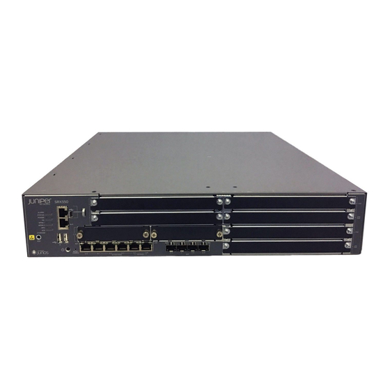
- Page 11 System Overview ........... 3 Figure 1: SRX550 High Memory Services Gateway ......3 Chapter 2 Chassis Description .
- Page 12 Chapter 17 Providing Power to the SRX550 High Memory Services Gateway ..115 Figure 25: Connecting an AC Power Cord ....... . 116 Figure 26: Connecting DC Power Cables .
- Page 13 Table 18: 1-Port Serial Mini-PIM (SRX-MP-1SERIAL-R) LED States ... . 33 Table 19: Juniper Networks Serial Cables ....... . 33 Table 20: 1-Port T1/E1 Mini-PIM (SRX-MP-1T1E1-R) Physical Specifications .
- Page 14 Initial Installation and Configuration Chapter 12 Unpacking the SRX550 High Memory Services Gateway ....91 Table 46: Parts List for a Fully Configured SRX550 High Memory Services Gateway .
- Page 15 Table 63: LED Indications for Hot-Swappable GPIM Components ... . 175 Table 64: Hot-Swappable Component Descriptions for GPIMs ....177 Copyright © 2016, Juniper Networks, Inc.
- Page 16 SRX550 High Memory Services Gateway Hardware Guide Copyright © 2016, Juniper Networks, Inc.
-
Page 17: About The Documentation
® To obtain the most current version of all Juniper Networks technical documentation, see the product documentation page on the Juniper Networks website at http://www.juniper.net/techpubs/ If the information in the latest release notes differs from the information in the documentation, follow the product Release Notes. -
Page 18: Table 1: Notice Icons
SRX550 High Memory Services Gateway Hardware Guide Table 1: Notice Icons Icon Meaning Description Informational note Indicates important features or instructions. Caution Indicates a situation that might result in loss of data or hardware damage. Warning Alerts you to the risk of personal injury or death. -
Page 19: Documentation Feedback
We encourage you to provide feedback, comments, and suggestions so that we can improve the documentation. You can provide feedback by using either of the following methods: Online feedback rating system—On any page of the Juniper Networks TechLibrary site , simply click the stars to rate the content, http://www.juniper.net/techpubs/index.html and use the pop-up form to provide us with information about your experience. -
Page 20: Requesting Technical Support
7 days a week, 365 days a year. Self-Help Online Tools and Resources For quick and easy problem resolution, Juniper Networks has designed an online self-service portal called the Customer Support Center (CSC) that provides you with the following features: Find CSC offerings: http://www.juniper.net/customers/support/... - Page 21 About the Documentation For international or direct-dial options in countries without toll-free numbers, see http://www.juniper.net/support/requesting-support.html Copyright © 2016, Juniper Networks, Inc.
- Page 22 SRX550 High Memory Services Gateway Hardware Guide xxii Copyright © 2016, Juniper Networks, Inc.
-
Page 23: Overview
PART 1 Overview System Overview on page 3 Chassis Description on page 13 Interface Module Description on page 23 Cooling System Description on page 39 Power System Description on page 41 Copyright © 2016, Juniper Networks, Inc. - Page 24 SRX550 High Memory Services Gateway Hardware Guide Copyright © 2016, Juniper Networks, Inc.
-
Page 25: System Overview
The services gateway simplifies network complexity, protects and prioritizes network resources, and improves user and application experience. The SRX550 High Memory Services Gateway has a modular 2U chassis that fits a 19-inch rack with a depth of approximately 18.1 inches. The SRX550 High Memory Services Gateway comes with 4 GB of DRAM memory and 8 GB of flash memory. -
Page 26: Srx550 High Memory Services Gateway Hardware Features
SRX550 High Memory Services Gateway Hardware Guide SRX550 High Memory Services Gateway Software Features and Licenses on page 4 SRX550 High Memory Services Gateway Hardware Features The SRX550 High Memory Services Gateway provides the following features: Symmetric Multiprocessing-based data forwarding. -
Page 27: System Overview
Virtual private LAN service (VPLS) Multicast VLAN NOTE: MPLS is available in both packet-based mode and selective packet mode. Internet IPv4 protocols IPv6 routing and forwarding IP address Static addresses management Dynamic Host Configuration Protocol (DHCP) 8 Copyright © 2016, Juniper Networks, Inc. - Page 28 SRX550 High Memory Services Gateway Hardware Guide Table 3: Software Features and Licenses (continued) Feature Category Feature Encapsulation Ethernet: Media access control (MAC) encapsulation 802.1p tagging Point-to-Point Protocol over Ethernet (PPPoE) Circuit cross-connect (CCC) Translational cross-connect (TCC) Synchronous Point-to-Point Protocol (PPP)
- Page 29 Junos OS command-line interface (CLI)—For services gateway configuration and management through the console through Telnet, or SSH Simple Network Management Protocol version 1 (SNMPv1), SNMPv2, and SNMPv3 Network and Security Manager (NSM) J-Flow flow monitoring and accounting Copyright © 2016, Juniper Networks, Inc.
-
Page 30: Srx550 High Memory Services Gateway Power Over Ethernet
Commit scripts Operation scripts Event policies Hot-swappable GPIMs and XPIMs are not hot-swappable on the SRX550 High Memory Services Gateway. Bypass ports LAN bypass ports are not supported on the SRX Series Services Gateways. Related SRX550 High Memory Services Gateway Description on page 3... -
Page 31: Table 4: Srx550 High Memory Services Gateway Poe Specifications
Voice over IP (VoIP) and IP phones and wireless access points. The PoE ports for the SRX550 High Memory Services Gateway reside on the individual XPIMs. The SRX550 High Memory Services Gateway supports the 16-Port Gigabit Ethernet XPIM with PoE. -
Page 32: Accessing The Srx550 High Memory Services Gateway
SRX550 High Memory Services Gateway Software Features and Licenses on page 4 SRX550 High Memory Services Gateway Boot Devices and Dual-Root Partitioning Scheme By default, the SRX550 High Memory Services Gateway boots from the following storage media (in order of priority): Internal CompactFlash card (default; always present) - Page 33 The services gateway remains fully functional even if it boots Junos OS from the backup root partition of storage media. Related Installation Overview for the SRX550 High Memory Services Gateway on page 87 Documentation Required Tools and Parts for Installing the SRX550 High Memory Services Gateway...
- Page 34 SRX550 High Memory Services Gateway Hardware Guide Copyright © 2016, Juniper Networks, Inc.
-
Page 35: Chassis Description
SRX550 High Memory Services Gateway Back Panel on page 19 SRX550 High Memory Services Gateway Chassis The SRX550 High Memory Services Gateway chassis is a rigid sheet metal structure that houses all the other hardware components. Table 5 on page 13 provides information about the physical specifications for the services gateway. -
Page 36: Srx550 High Memory Services Gateway Front Panel
General Electrical Safety Guidelines and Warnings on page 211 SRX550 High Memory Services Gateway Front Panel Figure 2 on page 14 shows the front panel of the SRX550 High Memory Services Gateway. Figure 2: SRX550 High Memory Services Gateway Front Panel Table 6 on page 14... - Page 37 Chapter 2: Chassis Description Table 6: SRX550 High Memory Services Gateway Front Panel Components (continued) Number Component Location Description USB Console Port Left side of the Connects a laptop to the services gateway for CLI front chassis panel management through a USB interface. The port accepts a Mini-B type USB cable plug.
- Page 38 SRX550 High Memory Services Gateway Hardware Guide Table 6: SRX550 High Memory Services Gateway Front Panel Components (continued) Number Component Location Description 6 fixed Gigabit Ethernet Left side of the The Gigabit Ethernet ports have the following characteristics: ports: front chassis panel, Use an RJ-45 connector.
-
Page 39: Srx550 High Memory Services Gateway Front Panel Leds
Figure 3 on page 17 shows how the slots on the front panel of the SRX550 High Memory Services Gateway are numbered. Figure 3: SRX550 High Memory Services Gateway Slot Numbers... -
Page 40: Table 7: Srx550 High Memory Services Gateway Front Panel Leds
SRX550 High Memory Services Gateway Hardware Guide Table 7: SRX550 High Memory Services Gateway Front Panel LEDs LED Label LED State LED Color Description ALARM On Steadily Amber Indicates a major alarm, such as low Services Processing Unit (SPU) memory (less than 10% remaining), session full, maximum number of VPN tunnels reached, high availability (HA) status changed, or redundant group member not found. -
Page 41: Srx550 High Memory Services Gateway Back Panel
Chapter 2: Chassis Description Table 7: SRX550 High Memory Services Gateway Front Panel LEDs (continued) LED Label LED State LED Color Description On Steadily Green The redundant power supply is operating normally. One of the following conditions has occurred: The primary power supply has failed, and the device is being powered by the redundant power supply. -
Page 42: Table 8: Srx550 High Memory Services Gateway Back Panel Components
SRX550 High Memory Services Gateway Hardware Guide Table 8: SRX550 High Memory Services Gateway Back Panel Components Number Component Location Description Usage Two power Left side of The power supply Power supplies are supply slots. back panel provides power to the... - Page 43 Chapter 2: Chassis Description Related SRX550 High Memory Services Gateway Chassis on page 13 Documentation SRX550 High Memory Services Gateway Front Panel on page 14 SRX550 High Memory Services Gateway Power Supply on page 41 Copyright © 2016, Juniper Networks, Inc.
- Page 44 SRX550 High Memory Services Gateway Hardware Guide Copyright © 2016, Juniper Networks, Inc.
-
Page 45: Interface Module Description
A double-high, single-wide LAN switch XPIM that uses two standard slots vertically Figure 6 on page 24 shows how the slots on the front panel of the SRX550 High Memory Services Gateway are numbered. Copyright © 2016, Juniper Networks, Inc. -
Page 46: Figure 6: Srx550 High Memory Services Gateway Slot Numbers
Related SRX550 High Memory Services Gateway Front Panel on page 14 Documentation SRX550 High Memory Services Gateway Power over Ethernet on page 8 8-Port Gigabit Ethernet SFP XPIM on page 25 16-Port Gigabit Ethernet XPIM (PoE) on page 29 SRX550 High Memory Services Gateway Mini-Physical Interface Modules Overview on page 31 Copyright ©... -
Page 47: 8-Port Gigabit Ethernet Sfp Xpim
CAUTION: If you are having a problem running a Juniper Networks device that is using a third-party optic or cable, the Juniper Networks Technical Assistance Center (JTAC) can help you diagnose the source of the problem. Your JTAC engineer might recommend that you check the third-party optic or cable and potentially replace it with an equivalent Juniper Networks optic or cable that is qualified for the device. -
Page 48: 8-Port Gigabit Ethernet Sfp Xpim Components
SRX550 High Memory Services Gateway Hardware Guide 8-Port Gigabit Ethernet SFP XPIM Components The 8-Port Gigabit Ethernet small form-factor pluggable Gigabit-Backplane Physical Interface Module (SFP XPIM) contains the components listed in Table 9 on page Table 9: 8-Port Gigabit Ethernet SFP XPIM Components... -
Page 49: 8-Port Gigabit Ethernet Sfp Xpim Supported Transceivers
EX-SFP-1GE-LX SRX-SFP-1GE-SX 1000BASE-SX EX-SFP-1GE-SX SRX-SFP-1GE-T 1000BASE-T, Copper Transceiver CAT-5e EX-SFP-1GE-T EX-SFP-GE10KT13R14 1000BASE-BX10, at 10 km (TX 1310 nm / RX 1490 nm) EX-SFP-GE10KT13R15 1000BASE-BX10, at 10 km (TX 1310 nm / RX 1550 nm) Copyright © 2016, Juniper Networks, Inc. -
Page 50: 8-Port Gigabit Ethernet Sfp Xpim Network Interface Specifications
DIX, LLC/SNAP, CCC, TCC, and VLAN-CCC Loopback diagnostic feature Supported Autonegotiation Supported Related SRX550 High Memory Services Gateway Gigabit-Backplane Physical Interface Modules Documentation Overview on page 23 16-Port Gigabit Ethernet XPIM (PoE) on page 29 Copyright © 2016, Juniper Networks, Inc. -
Page 51: 16-Port Gigabit Ethernet Xpim (Poe)
The 16-Port Gigabit Ethernet XPIM is a double-high, single-wide LAN switch Gigabit-Backplane Physical Interface Module (GPIM) that uses two standard slots vertically. It is available with or without Power over Ethernet (PoE) support. The SRX550 High Memory Services Gateway supports the PoE model. The PoE GPIMs provide ports that supply electric power over the same ports that are used to connect network devices. -
Page 52: 16-Port Gigabit Ethernet Xpim (Poe) Components
SRX550 High Memory Services Gateway Hardware Guide Maximum module power of 40 W without PoE JTAG support for boundary scan test 16-Port Gigabit Ethernet XPIM (PoE) Components The 16-Port Gigabit Ethernet XPIM contains the components listed in Table 14 on page... -
Page 53: 16-Port Gigabit Ethernet Xpim (Poe) Leds
1-Port T1/E1 Mini-Physical (SRX-MP-1T1E1-R) Interface Module on page 34 SRX550 High Memory Services Gateway Mini-Physical Interface Modules Overview The SRX550 High Memory Services Gateway has two slots (slots 1 and 2) for installing Mini-Physical Interface Modules (Mini-PIMs). A Mini-PIM is a network interface card that is installed in the services gateway to provide physical connections to a LAN or WAN. -
Page 54: Overview
Related SRX550 High Memory Services Gateway Front Panel on page 14 Documentation SRX550 High Memory Services Gateway Power over Ethernet on page 8 SRX550 High Memory Services Gateway Gigabit-Backplane Physical Interface Modules Overview on page 23 8-Port Gigabit Ethernet SFP XPIM on page 25... -
Page 55: 1-Port Serial Mini-Physical Interface Module (Srx-Mp-1Serial-R) Hardware Specifications
1-Port Serial Mini-Physical Interface Module Interface Cables Table 19 on page 33 lists the cables that you can order from Juniper Networks to connect to a port on the synchronous 1-Port Serial Mini-Physical Interface Module (Mini-PIM). The device to which you are connecting and the serial interface types determine which type of cable you need. -
Page 56: 1-Port T1/E1 Mini-Physical (Srx-Mp-1T1E1-R) Interface Module
JX-CBL-X21-DTE X.21 cable (DTE) 3.04 m (10 ft) Male Related SRX550 High Memory Services Gateway Gigabit-Backplane Physical Interface Modules Documentation Overview on page 23 8-Port Gigabit Ethernet SFP XPIM on page 25 16-Port Gigabit Ethernet XPIM (PoE) on page 29... -
Page 57: 1-Port T1/E1 Mini-Physical Interface Module (Srx-Mp-1T1E1-R) Hardware Specifications
–40°F through 158°F (–40°C through 70°C) Relative humidity 5% to 90% noncondensing 1-Port T1/E1 Mini-Physical Interface Module (SRX-MP-1T1E1-R) LEDs The 1-Port T1/E1 Mini-Physical Interface Module (Mini-PIM) has three LEDs. Table 21 on page 36 describes the LED states. Copyright © 2016, Juniper Networks, Inc. -
Page 58: 1-Port T1/E1 Mini-Physical Interface Module (Srx-Mp-1T1E1-R) Supported Loopback Diagnostics
SRX550 High Memory Services Gateway Hardware Guide Table 21: 1-Port T1/E1 Mini-PIM (SRX-MP-1T1E1-R) LED States Color State Description ALARM Yellow Indicates that there is a local or remote alarm; device has detected a failure. Indicates that there are no alarms or failures. -
Page 59: 1-Port T1/E1 Mini-Physical Interface Module (Srx-Mp-1T1E1-R) Network Interface Specifications
Runts, Giants, FCS, Error, Abort Error, Align Error Error, Align Error Related SRX550 High Memory Services Gateway Gigabit-Backplane Physical Interface Modules Documentation Overview on page 23 8-Port Gigabit Ethernet SFP XPIM on page 25 16-Port Gigabit Ethernet XPIM (PoE) on page 29... - Page 60 SRX550 High Memory Services Gateway Hardware Guide Copyright © 2016, Juniper Networks, Inc.
-
Page 61: Cooling System Description
SRX550 High Memory Services Gateway Cooling System on page 39 SRX550 High Memory Services Gateway Cooling System The SRX550 High Memory Services Gateway cooling system consists of four fixed fans. The fans provide cooling to the components installed in the services gateway. To function properly, the entire cooling system requires an unobstructed airflow and proper clearance around the site. - Page 62 SRX550 High Memory Services Gateway Hardware Guide Copyright © 2016, Juniper Networks, Inc.
-
Page 63: Power System Description
SRX550 High Memory Services Gateway Power Supply on page 41 SRX550 High Memory Services Gateway Power Supply The SRX550 High Memory Services Gateway uses either one AC or one DC power supply unit (PSU). The services gateway is equipped with one AC power supply (see Figure 13 on page 41) for non-power redundancy. -
Page 64: Figure 14: Dc Power Supply
SRX550 High Memory Services Gateway Hardware Guide Figure 14: DC Power Supply The power supplies provide different output wattage to the services gateway components according to the voltage requirements of the components. The power supply components are listed in Table 23 on page... -
Page 65: Table 24: Dc Power Supply Terminals
SRX550 High Memory Services Gateway Back Panel on page 19 SRX550 High Memory Services Gateway Cooling System on page 39 Troubleshooting the Power System on the SRX550 High Memory Services Gateway on page 150 Copyright © 2016, Juniper Networks, Inc. - Page 66 SRX550 High Memory Services Gateway Hardware Guide Copyright © 2016, Juniper Networks, Inc.
-
Page 67: Site Planning And Specifications
Site Planning and Specifications Planning and Preparing the Site on page 47 Rack Requirements on page 53 Cabinet Requirements on page 61 Power Requirements and Specifications on page 63 Cable Specifications and Pinouts on page 69 Copyright © 2016, Juniper Networks, Inc. - Page 68 SRX550 High Memory Services Gateway Hardware Guide Copyright © 2016, Juniper Networks, Inc.
-
Page 69: Planning And Preparing The Site
CHAPTER 6 Planning and Preparing the Site Site Preparation Checklist for the SRX550 High Memory Services Gateway on page 47 General Site Installation Guidelines for the SRX550 High Memory Services Gateway on page 49 SRX550 High Memory Services Gateway Environmental Specifications on page 50... - Page 70 SRX550 High Memory Services Gateway Hardware Guide Table 25: Site Preparation Checklist for SRX550 High Memory Services Gateway Installation (continued) Performed Item or Task Additional Information Date Notes Verify that “SRX550 High Memory Services environmental Gateway Environmental factors such as Specifications”...
-
Page 71: Gateway
Related SRX550 High Memory Services Gateway Chassis on page 13 Documentation Installation Overview for the SRX550 High Memory Services Gateway on page 87 General Site Installation Guidelines for the SRX550 High Memory Services Gateway on page 49 General Site Installation Guidelines for the SRX550 High Memory Services Gateway... -
Page 72: Srx550 High Memory Services Gateway Environmental Specifications
Documentation SRX550 High Memory Services Gateway Cabinet Size and Clearance Requirements on page 61 SRX550 High Memory Services Gateway Rack Size and Strength Requirements on page 57 Clearance Requirements for Airflow and Hardware Maintenance of the SRX550 High Memory Services Gateway on page 58... - Page 73 Chapter 6: Planning and Preparing the Site Related SRX550 High Memory Services Gateway General Safety Guidelines and Warnings on Documentation page 191 Routine Maintenance Procedures for the SRX550 High Memory Services Gateway on page 143 Copyright © 2016, Juniper Networks, Inc.
- Page 74 SRX550 High Memory Services Gateway Hardware Guide Copyright © 2016, Juniper Networks, Inc.
-
Page 75: Rack Requirements
Rack-Mounting Requirements and Warnings on page 53 SRX550 High Memory Services Gateway Rack Size and Strength Requirements on page 57 SRX550 High Memory Services Gateway Spacing of Mounting Bracket and Flange Holes on page 57 Clearance Requirements for Airflow and Hardware Maintenance of the SRX550 High... - Page 76 Les directives ci-dessous sont destinées à assurer la protection du personnel: Le rack sur lequel est monté le Juniper Networks services gateway doit être fixé à la structure du bâtiment. Si cette unité constitue la seule unité montée en casier, elle doit être placée dans le bas.
-
Page 77: Rack Requirements
Le seguenti direttive vengono fornite per garantire la sicurezza personale: Il Juniper Networks services gateway deve essere installato in un telaio, il quale deve essere fissato alla struttura dell'edificio. Questa unità deve venire montata sul fondo del supporto, se si tratta dell'unica unità... - Page 78 Om ställningen är försedd med stabiliseringsdon skall dessa monteras fast innan enheten installeras eller underhålls på ställningen. Related SRX550 High Memory Services Gateway General Safety Guidelines and Warnings on Documentation page 191 Copyright © 2016, Juniper Networks, Inc.
-
Page 79: Requirements
SRX550 High Memory Services Gateway Rack Size and Strength Requirements When installing the SRX550 High Memory Services Gateway in a rack, you must ensure that the rack complies with a 2U (19 in. or 45.6 cm) rack as defined in Cabinets, Racks,... -
Page 80: Clearance Requirements For Airflow And Hardware Maintenance Of The Srx550 High Memory Services Gateway
SRX550 High Memory Services Gateway Hardware Guide SRX550 High Memory Services Gateway Cabinet Size and Clearance Requirements on page 61 Site Preparation Checklist for the SRX550 High Memory Services Gateway on page 47 SRX550 High Memory Services Gateway Rack Size and Strength Requirements on page 57... -
Page 81: Table 27: Clearance Requirements For The Srx550 High Memory Services
Documentation SRX550 High Memory Services Gateway Cabinet Size and Clearance Requirements on page 61 Site Preparation Checklist for the SRX550 High Memory Services Gateway on page 47 SRX550 High Memory Services Gateway Rack Size and Strength Requirements on page 57... - Page 82 SRX550 High Memory Services Gateway Hardware Guide Copyright © 2016, Juniper Networks, Inc.
-
Page 83: Cabinet Requirements
SRX550 High Memory Services Gateway Cabinet Airflow Requirements on page 62 SRX550 High Memory Services Gateway Cabinet Size and Clearance Requirements You can install the SRX550 High Memory Services Gateway in a 19 in. (48.3 cm) cabinet as defined in Cabinets, Racks, Panels, and Associated Equipment (document number EIA-310-D) published by the Electronic Industries Alliance http://www.ecaus.org/eia/site/index.html... -
Page 84: Srx550 High Memory Services Gateway Cabinet Airflow Requirements
Memory Services Gateway on page 58 SRX550 High Memory Services Gateway Cabinet Airflow Requirements When you mount the SRX550 High Memory Services Gateway in a cabinet, you must ensure that ventilation through the cabinet is sufficient to prevent overheating. Consider... -
Page 85: Power Requirements And Specifications
Power Requirements and Specifications SRX550 High Memory Services Gateway Electrical Wiring Guidelines on page 63 SRX550 High Memory Services Gateway Supported AC Power Cords on page 64 SRX550 High Memory Services Gateway AC Power Supply Electrical Specifications on page 66... -
Page 86: Srx550 High Memory Services Gateway Supported Ac Power Cords
General Site Installation Guidelines for the SRX550 High Memory Services Gateway Documentation on page 49 Maintaining the SRX550 High Memory Services Gateway Power Supply on page 144 SRX550 High Memory Services Gateway Environmental Specifications on page 50 SRX550 High Memory Services Gateway Supported AC Power Cords... -
Page 87: Figure 16: Ac Plug Types
Clearance Requirements for Airflow and Hardware Maintenance of the SRX550 High Memory Services Gateway on page 58 SRX550 High Memory Services Gateway Electrical Wiring Guidelines on page 63 Site Preparation Checklist for the SRX550 High Memory Services Gateway on page 47 Copyright © 2016, Juniper Networks, Inc. -
Page 88: Specifications
Memory Services Gateway on page 58 SRX550 High Memory Services Gateway Electrical Wiring Guidelines on page 63 Site Preparation Checklist for the SRX550 High Memory Services Gateway on page 47 SRX550 High Memory Services Gateway DC Power Cable Specifications The DC power supply in slot... -
Page 89: Specifications
Memory Services Gateway on page 58 SRX550 High Memory Services Gateway Electrical Wiring Guidelines on page 63 Site Preparation Checklist for the SRX550 High Memory Services Gateway on page 47 SRX550 High Memory Services Gateway DC Power Supply Electrical Specifications... - Page 90 SRX550 High Memory Services Gateway Hardware Guide Copyright © 2016, Juniper Networks, Inc.
-
Page 91: Cable Specifications And Pinouts
CHAPTER 10 Cable Specifications and Pinouts Interface Cabling and Wiring Specifications for the SRX550 High Memory Services Gateway on page 69 RJ-45 Connector Pinouts for the SRX550 High Memory Services Gateway Ethernet Port on page 70 RJ-45 Connector Pinouts for the SRX550 High Memory Services Gateway Console... -
Page 92: Connector Pinouts For The Srx550 High Memory Services Gateway Ethernet Port
(100 m) autosensing for 100Base-T connectors operation NOTE: The Auxiliary port is not supported on the SRX550 High Memory Services Gateway. Related RJ-45 Connector Pinouts for the SRX550 High Memory Services Gateway Ethernet Documentation Port on page 70 RJ-45 Connector Pinouts for the SRX550 High Memory Services Gateway Console... -
Page 93: Connector Pinouts For The Srx550 High Memory Services Gateway Console Port
Port (continued) Signal Termination network Termination network Related RJ-45 Connector Pinouts for the SRX550 High Memory Services Gateway Console Documentation Port on page 71 Interface Cabling and Wiring Specifications for the SRX550 High Memory Services Gateway on page 69 RJ-45 Connector Pinouts for the SRX550 High Memory Services Gateway Console... -
Page 94: Module
SRX550 High Memory Services Gateway Hardware Guide EIA-530A DCE Cable Pinouts for the 1-Port Serial Mini-Physical Interface Module Table 36 on page 72 gives the EIA-530A DCE cable pinouts. Table 36: EIA-530A DCE Cable Pinouts for the 1-Port Serial Mini-PIM... -
Page 95: Module
Shield Ground Transmit Data (A) Receive Data (A) Request to Send (A) Clear to Send (A) Data Set Ready (A) Signal Ground Received Line Signal Detector (A) Receive Clock (B) Received Line Signal Detector (B) Copyright © 2016, Juniper Networks, Inc. -
Page 96: Module
SRX550 High Memory Services Gateway Hardware Guide Table 37: EIA-530A DTE Cable Pinouts for the 1-Port Serial Mini-PIM (continued) LFH-60 LFH-60 Pin DB-25 Pin Pairing Description Terminal Timing (B) Transmit Clock (B) Clear to Send (B) Transmit Data (B) Transmit Clock (A) -
Page 97: Module
X.21 DCE Cable Pinouts for the 1-Port Serial Mini-Physical Interface Module on page 82 RS-232 DTE Cable Pinouts for the 1-Port Serial Mini-Physical Interface Module Table 39 on page 76 gives the RS-232 DTE cable pinouts. Copyright © 2016, Juniper Networks, Inc. -
Page 98: Interface Module
SRX550 High Memory Services Gateway Hardware Guide Table 39: RS-232 DTE Cable Pinouts for the 1-Port Serial Mini-PIM LFH-60 LFH-60 Pin DB-25 Pin Pairing Description Frame Ground Transmit Data Receive Data Request to Send Clear to Send Data Set Ready... -
Page 99: Table 40: Rs-422/449 Dce Cable Pinouts For The 1-Port Serial Mini-Pim
Terminal Timing (A) Signal Ground Receive Common Send Data (B) Send Timing (B) Receive Data (B) Request to Send (B) Receive Timing (B) Clear to Send (B) Data Mode (B) Terminal Ready (B) Receiver Ready (B) Copyright © 2016, Juniper Networks, Inc. -
Page 100: Interface Module
SRX550 High Memory Services Gateway Hardware Guide Table 40: RS-422/449 DCE Cable Pinouts for the 1-Port Serial Mini-PIM (continued) DC-37 LFH-60 LFH-60 Pin (DB-37) Pin Pairing Description Terminal Timing (B) Send Common 26 to 25 Related EIA-530A DCE Cable Pinouts for the 1-Port Serial Mini-Physical Interface Module on... - Page 101 RS-232 DTE Cable Pinouts for the 1-Port Serial Mini-Physical Interface Module on page 75 V.35 DTE Cable Pinouts for the 1-Port Serial Mini-Physical Interface Module on page 81 X.21 DTE Cable Pinouts for the 1-Port Serial Mini-Physical Interface Module on page 83 Copyright © 2016, Juniper Networks, Inc.
-
Page 102: Dce Cable Pinouts For The 1-Port Serial Mini-Physical Interface Module
SRX550 High Memory Services Gateway Hardware Guide V.35 DCE Cable Pinouts for the 1-Port Serial Mini-Physical Interface Module Table 42 on page 80 gives the V.35 DCE cable pinouts. Table 42: V.35 DCE Cable Pinouts for the 1-Port Serial Mini-PIM... -
Page 103: Dte Cable Pinouts For The 1-Port Serial Mini-Physical Interface Module
Data Set Ready Received Line Signal Detector Data Terminal Ready Test Mode Transmit Data (A) Receive Data (A) Transmit Data (B) Receive Data (B) Terminal Timing (A) Receive Timing (A) Terminal Timing (B) Receive Timing (B) Copyright © 2016, Juniper Networks, Inc. -
Page 104: X.21 Dce Cable Pinouts For The 1-Port Serial Mini-Physical Interface Module
SRX550 High Memory Services Gateway Hardware Guide Table 43: V.35 DTE Cable Pinouts for the 1-Port Serial Mini-PIM (continued) LFH-60 LFH-60 Pin M/34 Pin Pairing Description Transmit Timing (A) Transmit Timing (B) 22 to 21 26 to 25 18 to 17... -
Page 105: Dte Cable Pinouts For The 1-Port Serial Mini-Physical Interface Module
Table 45: X.21 DTE Cable Pinouts for the 1-Port Serial Mini-PIM LFH-60 Pin DB-15 Pin LFH-60 Pairing Description Shield Ground Transmit Data (A) Control (A) Receive (A) Indicate (A) Signal Element Timing (A) Signal Ground Transmit Data (B) Control (B) Receive (B) Indicate (B) Copyright © 2016, Juniper Networks, Inc. - Page 106 SRX550 High Memory Services Gateway Hardware Guide Table 45: X.21 DTE Cable Pinouts for the 1-Port Serial Mini-PIM (continued) LFH-60 Pin DB-15 Pin LFH-60 Pairing Description Signal Element Timing (B) 30 to 29 18 to 17 Related EIA-530A DTE Cable Pinouts for the 1-Port Serial Mini-Physical Interface Module on...
-
Page 107: Initial Installation And Configuration
Installing the SRX550 High Memory Services Gateway on page 97 Grounding the SRX550 High Memory Services Gateway on page 105 Connecting the SRX550 High Memory Services Gateway to External Devices on page 109 Providing Power to the SRX550 High Memory Services Gateway on page 115 Performing Initial Configuration on page 123 Copyright ©... - Page 108 SRX550 High Memory Services Gateway Hardware Guide Copyright © 2016, Juniper Networks, Inc.
-
Page 109: Installation Overview
SRX550 High Memory Services Gateway Autoinstallation Overview on page 89 Installation Overview for the SRX550 High Memory Services Gateway After you have prepared the site for installation and unpacked the SRX550 High Memory Services Gateway, you are ready to install the device. It is important to proceed through... -
Page 110: Gateway
Related Installation Overview for the SRX550 High Memory Services Gateway on page 87 Documentation Installing the SRX550 High Memory Services Gateway in a Rack on page 97 SRX550 High Memory Services Gateway Safety Requirements, Warnings, and Guidelines on page 192... -
Page 111: Srx550 High Memory Services Gateway Autoinstallation Overview
CLI. For more information about the autoinstallation feature, see the Installation and Upgrade Guide for Security Devices Related Installation Overview for the SRX550 High Memory Services Gateway on page 87 Documentation Required Tools and Parts for Installing the SRX550 High Memory Services Gateway... - Page 112 SRX550 High Memory Services Gateway Hardware Guide Copyright © 2016, Juniper Networks, Inc.
-
Page 113: Unpacking The Srx550 High Memory Services Gateway
Phillips (+) screwdriver, number 2 Blank panels to cover any slots not occupied by a component The SRX550 High Memory Services Gateway is shipped in a cardboard carton and secured with foam packing material. The carton also contains an accessory box and quick start instructions. -
Page 114: Verifying Parts Received With The Srx550 High Memory Services Gateway
Component Quantity 2U SRX550 High Memory Services Gateway chassis with 6 GPIM slots, 2 Mini-PIM slots, 1 ACE slot, 2 power supply slots, 6 10/100/1000 base-T ports, and 4 Gigabit Ethernet SFP ports. Includes blank covers for GPIM slots (6 covers for GPIM slots), Mini-PIM slots, ACE slot, and power supply slots. -
Page 115: Table 47: Accessory/Upgrade Parts List For The Srx550 High Memory Services
Chapter 12: Unpacking the SRX550 High Memory Services Gateway Table 46: Parts List for a Fully Configured SRX550 High Memory Services Gateway (continued) Component Quantity 645 W AC power supply or 645 W DC power supply with PoE support 645 W AC power supply provides 390 W system power at 12 V; 255 W PoE power on a single power supply, or with redundancy using the two power supply option;... - Page 116 SRX550 High Memory Services Gateway Hardware Guide Copyright © 2016, Juniper Networks, Inc.
-
Page 117: Installing The Mounting Hardware
Structure on page 96 Preparing the SRX550 High Memory Services Gateway for Rack-Mount Installation You can mount an SRX550 High Memory Services Gateway on four-post (telco) racks, enclosed cabinets, and open-frame racks. Center-mount racks are not supported. Before mounting the SRX550 High Memory Services Gateway in a rack: Verify that the site meets the requirements described in “Site Preparation Checklist... - Page 118 SRX550 High Memory Services Gateway Hardware Guide Connecting the SRX550 High Memory Services Gateway to the Building Structure Always secure the rack in which you are installing the SRX550 High Memory Services Gateway to the structure of the building. If your geographical area is subject to earthquakes, bolt the rack to the floor.
-
Page 119: Installing The Srx550 High Memory Services Gateway
Installing an AC Power Supply on the SRX550 High Memory Services Gateway on page 99 Installing a DC Power Supply on the SRX550 High Memory Services Gateway on page 100 Installing the SRX550 High Memory Services Gateway in a Rack You can front-mount the SRX550 High Memory Services Gateway in a rack. -
Page 120: Figure 18: Installing The Rack Mount Brackets (Center Mount Position)
SRX550 High Memory Services Gateway Hardware Guide Figure 18: Installing the Rack Mount Brackets (Center Mount Position) Have one person grasp the sides of the services gateway, lift it, and position it in the rack. Align the bottom hole in each mounting bracket with a hole in each rack rail, making sure the chassis is level. -
Page 121: Gateway
Chapter 14: Installing the SRX550 High Memory Services Gateway Related Installation Overview for the SRX550 High Memory Services Gateway on page 87 Documentation SRX550 High Memory Services Gateway Rack Size and Strength Requirements on page 57 SRX550 High Memory Services Gateway Spacing of Mounting Bracket and Flange... -
Page 122: Installing A Dc Power Supply On The Srx550 High Memory Services
Required Tools and Parts for Replacing Hardware Components on the SRX550 High Memory Services Gateway on page 159 Removing an AC Power Supply from the SRX550 High Memory Services Gateway on page 162 Disconnecting an AC Power Cord from the SRX550 High Memory Services Gateway... - Page 123 Chapter 14: Installing the SRX550 High Memory Services Gateway Tighten the captive screws on the lower edge of the power supply faceplate. Remove the clear plastic cover protecting the terminal studs on the faceplate. Verify that the DC power cables are correctly labeled before making connections to the power supply.
-
Page 124: Figure 22: Connecting Dc Power Cables
Gateway on page 194 Required Tools and Parts for Replacing Hardware Components on the SRX550 High Memory Services Gateway on page 159 Removing a DC Power Supply from the SRX550 High Memory Services Gateway on page 166 Copyright © 2016, Juniper Networks, Inc. - Page 125 Chapter 14: Installing the SRX550 High Memory Services Gateway Removing a DC Power Supply Cable from the SRX550 High Memory Services Gateway on page 165 Copyright © 2016, Juniper Networks, Inc.
- Page 126 SRX550 High Memory Services Gateway Hardware Guide Copyright © 2016, Juniper Networks, Inc.
-
Page 127: Grounding The Srx550 High Memory Services Gateway
SRX550 High Memory Services Gateway Grounding Specifications To meet safety and electromagnetic interference (EMI) requirements and to ensure proper operation, the SRX550 High Memory Services Gateway must be adequately grounded before power is connected. You must provide a grounding lug to connect the services gateway to earth ground. -
Page 128: Grounding The Srx550 High Memory Services Gateway
SRX550 High Memory Services Gateway Hardware Guide Connecting the SRX550 High Memory Services Gateway to a DC Power Source on page 117 Powering On the SRX550 High Memory Services Gateway on page 120 Powering Off the SRX550 High Memory Services Gateway on page 120... - Page 129 Powering On the SRX550 High Memory Services Gateway on page 120 Powering Off the SRX550 High Memory Services Gateway on page 120 Organizing Interface Cables on the SRX550 High Memory Services Gateway on page 109 SRX550 High Memory Services Gateway General Safety Guidelines and Warnings on page 191 Copyright ©...
- Page 130 SRX550 High Memory Services Gateway Hardware Guide Copyright © 2016, Juniper Networks, Inc.
-
Page 131: Devices
Connecting the Modem to the Console Port on the SRX550 High Memory Services Gateway on page 110 Connecting to the SRX550 High Memory Services Gateway from the CLI with the USB Console Port on page 110 Connecting the CLI at the User End for the SRX550 High Memory Services... -
Page 132: Connecting The Modem To The Console Port On The Srx550 High Memory Services Gateway
SRX550 High Memory Services Gateway Hardware Guide Connecting the Modem to the Console Port on the SRX550 High Memory Services Gateway To connect the dial-up modem to the console port on the SRX550 High Memory Services Gateway: Turn off power to the services gateway. -
Page 133: Figure 24: Connecting To The Usb Console Port On The Srx550 High Memory
Chapter 16: Connecting the SRX550 High Memory Services Gateway to External Devices Figure 24: Connecting to the USB Console Port on the SRX550 High Memory Services Gateway To connect to the CLI using a local management device through the USB console port... -
Page 134: Connecting The Cli At The User End For The Srx550 High Memory Services Gateway
Connecting to the SRX550 High Memory Services Gateway from the CLI Remotely on page 133 Connecting the CLI at the User End for the SRX550 High Memory Services Gateway To connect to the CLI through a dial-up modem connected to the console port on the SRX550 High Memory Services Gateway: Connect a modem at your remote location to a management device. -
Page 135: Configuring The Modem At The Srx550 High Memory Services Gateway End
Configuring the Modem at the SRX550 High Memory Services Gateway End Before you can connect a dial-up modem to the console port on the SRX550 High Memory Services Gateway, you must configure the modem to accept a call on the first ring and to accept DTR signals. -
Page 136: Table 51: Port Settings
Connecting the Modem to the Console Port on the SRX550 High Memory Services Gateway on page 110 Connecting the CLI at the User End for the SRX550 High Memory Services Gateway on page 112 Copyright © 2016, Juniper Networks, Inc. -
Page 137: Providing Power To The Srx550 High Memory Services Gateway
Do not mix AC and DC power supplies within the same services gateway because this can damage the device. A 645 W AC power supply with PoE support ships with the SRX550 High Memory Services Gateway. You connect AC power to the services gateway by attaching the power cord from the AC power source to the AC appliance inlet located on the power supply. -
Page 138: Figure 25: Connecting An Ac Power Cord
Gateway on page 194 Grounding the SRX550 High Memory Services Gateway on page 106 Organizing Interface Cables on the SRX550 High Memory Services Gateway on page 109 SRX550 High Memory Services Gateway General Safety Guidelines and Warnings on page 191... - Page 139 CAUTION: Do not mix AC and DC power supplies within the same services gateway. Damage to the device might occur. A 645 W DC power supply with PoE support is available for the SRX550 High Memory Services Gateway. WARNING: Before performing the following procedure, ensure that power is removed from the DC circuit.
- Page 140 SRX550 High Memory Services Gateway Hardware Guide NOTE: The DC cable should be of minimum 14 AWG. CAUTION: You must ensure that power connections maintain the proper polarity. The power source cables might be labeled to indicate (–) their polarity. There is no standard color coding for DC power cables. The...
-
Page 141: Figure 26: Connecting Dc Power Cables
Gateway on page 194 Grounding the SRX550 High Memory Services Gateway on page 106 Organizing Interface Cables on the SRX550 High Memory Services Gateway on page 109 SRX550 High Memory Services Gateway General Safety Guidelines and Warnings on page 191... -
Page 142: Powering On The Srx550 High Memory Services Gateway
The POWER LED (on the front panel of the chassis) lights during startup and remains on steadily when the services gateway is operating normally. Related Connecting the SRX550 High Memory Services Gateway to the AC Power Source on Documentation page 115... - Page 143 Chapter 17: Providing Power to the SRX550 High Memory Services Gateway NOTE: Graceful shutdown is not supported on the SRX550 High Memory Services Gateway. To remove power completely from the services gateway, unplug the AC power cord or DC power supply cable.
- Page 144 SRX550 High Memory Services Gateway Hardware Guide Copyright © 2016, Juniper Networks, Inc.
-
Page 145: Performing Initial Configuration
Performing Initial Configuration SRX550 High Memory Services Gateway Basic Connectivity Overview on page 123 Built-In Ethernet Ports for the SRX550 High Memory Services Gateway on page 124 Management Access for the SRX550 High Memory Services Gateway on page 127 Viewing Factory-Default Settings of the SRX550 High Memory Services... -
Page 146: Built-In Ethernet Ports For The Srx550 High Memory Services Gateway
Documentation Configuring the SRX550 High Memory Services Gateway Using J-Web on page 129 Connecting to the SRX550 High Memory Services Gateway from the CLI Locally on page 131 Connecting to the SRX550 High Memory Services Gateway from the CLI Remotely on... -
Page 147: Table 53: Default Interface Configuration For The Services Gateway
( fxp1 ge-0/0/2 (if RJ-45 Trust Server 192.168.2.1/24 used) NOTE: this port as a fabric port. ge-0/0/3 (if RJ-45 Trust Server 192.168.3.1/24 used) NOTE: this port as a fabric port. Copyright © 2016, Juniper Networks, Inc. -
Page 148: Table 54: Security Policies
SRX550 High Memory Services Gateway Hardware Guide Table 53: Default Interface Configuration for the Services Gateway (continued) Security DHCP Port Label Interface Connector Zone State Address ge-0/0/4 RJ-45 Trust Server 192.168.4.1/24 ge-0/0/5 RJ-45 Trust Server 192.168.5.1/24 ge-0/0/6 No default configuration... -
Page 149: Management Access For The Srx550 High Memory Services Gateway
SRX550 High Memory Services Gateway Basic Connectivity Overview on page 123 Management Access for the SRX550 High Memory Services Gateway Telnet allows you to connect to the SRX550 High Memory Services Gateway and access the CLI to execute commands from a remote system. Telnet connections are not encrypted and therefore can be intercepted. -
Page 150: Viewing Factory-Default Settings Of The Srx550 High Memory Services
SRX550 High Memory Services Gateway Hardware Guide Connecting to the SRX550 High Memory Services Gateway from the CLI Remotely on page 133 Configuring the SRX550 High Memory Services Gateway Using J-Web on page 129 Viewing Factory-Default Settings of the SRX550 High Memory Services Gateway To view the factory-default configuration of the services gateway using the CLI: Verify that the services gateway is powered on. -
Page 151: Configuring The Srx550 High Memory Services Gateway Using J-Web
For more details about configuring secure web access on your services gateway, see the Installation and Upgrade Guide for Security Devices Related SRX550 High Memory Services Gateway Basic Connectivity Overview on page 123 Documentation Configuring the SRX550 High Memory Services Gateway Using J-Web... -
Page 152: Connect The Management Device To The Ethernet Port
Connect the Management Device to the Ethernet Port To connect the management device to the Ethernet port on the SRX550 High Memory Services Gateway: Connect any of the network ports numbered 0/1 through 0/5 to the Ethernet port on the management device, using an RJ-45 cable. -
Page 153: Verify The Settings
Configuring the SRX550 High Memory Services Gateway Using the CLI on page 134 Documentation Connecting to the SRX550 High Memory Services Gateway from the CLI Locally To use the CLI to configure the SRX550 High Memory Services Gateway, you must connect through the console port, as shown in Figure 28 on page 132. -
Page 154: Figure 28: Connecting To The Console Port On The Srx550 High Memory Services
SRX550 High Memory Services Gateway Hardware Guide Figure 28: Connecting to the Console Port on the SRX550 High Memory Services Gateway NOTE: Figure 28 on page 132 shows a connection to a local management device. A remote connection to the services gateway through a modem requires the cable and connector shown (RJ-45 to a DB-9 serial port adapter), along with an adapter for your modem, which you must purchase separately. -
Page 155: Remotely
133 Connecting to the SRX550 High Memory Services Gateway from the CLI Remotely You can connect an SRX550 High Memory Services Gateway to the CLI from a remote location through two dial-up modems: A modem that is connected to the console port on the services gateway... -
Page 156: Configuring The Srx550 High Memory Services Gateway Using The Cli
SRX550 High Memory Services Gateway Hardware Guide Configuring the SRX550 High Memory Services Gateway Using the CLI This procedure connects the device to the network but does not enable it to forward traffic. For complete information about enabling the device to forward traffic, including examples, see the appropriate Junos OS configuration guides. - Page 157 When you have finished configuring the services gateway, exit configuration mode. [edit] admin@device# exit admin@device> Related Connecting to the SRX550 High Memory Services Gateway from the CLI Locally on Documentation page 131 Connecting to the SRX550 High Memory Services Gateway from the CLI Remotely on page 133...
-
Page 158: Configuring Gigabit-Backplane Physical Interface Modules
SRX550 High Memory Services Gateway Hardware Guide Configuring Gigabit-Backplane Physical Interface Modules To configure Gigabit-Backplane Physical Interface Modules (GPIMs) on the SRX550 High Memory Services Gateway: Verify that the GPIM is installed in the services gateway: user@host >show chassis hardware The following is a sample output of the command. -
Page 159: Configuring Mini-Physical Interface Modules
Set security policies: [edit] user@host# set security policies default-policy permit-all Related SRX550 High Memory Services Gateway Gigabit-Backplane Physical Interface Modules Documentation Overview on page 23 8-Port Gigabit Ethernet SFP XPIM on page 25 16-Port Gigabit Ethernet XPIM (PoE) on page 29... -
Page 160: Using The Cli
SRX550 High Memory Services Gateway Hardware Guide Add a security zone to the interface: Select Configure>Security>Zones/Screens Add or select a security zone other than Null; for example, Trust . Assign the interface to the zone. For Host Inbound Traffic-Zone, set the following:... - Page 161 1-Port T1/E1 Mini-PIM to function as a T1 or an E1 e1–1/0/0 interface. Related SRX550 High Memory Services Gateway Mini-Physical Interface Modules Overview Documentation on page 31 1-Port Serial Mini-Physical (SRX-MP-1SERIAL-R) Interface Module on page 32 1-Port T1/E1 Mini-Physical (SRX-MP-1T1E1-R) Interface Module on page 34...
- Page 162 SRX550 High Memory Services Gateway Hardware Guide Copyright © 2016, Juniper Networks, Inc.
-
Page 163: Maintaining And Troubleshooting Components
PART 4 Maintaining and Troubleshooting Components Maintaining Components on page 143 Troubleshooting Components on page 145 Copyright © 2016, Juniper Networks, Inc. - Page 164 SRX550 High Memory Services Gateway Hardware Guide Copyright © 2016, Juniper Networks, Inc.
-
Page 165: Maintaining Components
CHAPTER 19 Maintaining Components Required Tools and Parts for Maintaining the SRX550 High Memory Services Gateway Hardware Components on page 143 Routine Maintenance Procedures for the SRX550 High Memory Services Gateway on page 143 Maintaining the SRX550 High Memory Services Gateway Cooling System... -
Page 166: Maintaining The Srx550 High Memory Services Gateway Power Supply
Check the status LEDs on the front and back panels of the services gateway. Related Required Tools and Parts for Maintaining the SRX550 High Memory Services Gateway Documentation Hardware Components on page 143 Maintaining the SRX550 High Memory Services Gateway Cooling System Components... -
Page 167: Troubleshooting Components
CHAPTER 20 Troubleshooting Components Troubleshooting with the CLI on the SRX550 High Memory Services Gateway on page 145 Troubleshooting with LEDs on the SRX550 High Memory Services Gateway on page 146 Troubleshooting with Chassis and Interface Alarm Messages on the SRX550 High... -
Page 168: Troubleshooting With Leds On The Srx550 High Memory Services Gateway
SRX550 High Memory Services Gateway Hardware Guide Troubleshooting with LEDs on the SRX550 High Memory Services Gateway The LEDs available on the services gateway display the status of various components. Table 58 on page 146 describes the LEDs on the chassis. -
Page 169: Troubleshooting With Chassis And Interface Alarm Messages On The Srx550
Mini-PIM is not detected by the device. Related Troubleshooting with the CLI on the SRX550 High Memory Services Gateway on page 145 Documentation SRX550 High Memory Services Gateway Front Panel on page 14 Troubleshooting with Chassis and Interface Alarm Messages on the SRX550 High... -
Page 170: Troubleshooting With Chassis And Interface Alarm Messages On The Srx550 High Memory Services Gateway
SRX550 High Memory Services Gateway Hardware Guide Troubleshooting with Chassis and Interface Alarm Messages on the SRX550 High Memory Services Gateway When the services gateway detects an alarm condition, it lights the red or yellow alarm LED on the front panel as appropriate. For a detailed description of the alarm condition, issue the CLI command. -
Page 171: Troubleshooting The Power System On The Srx550 High Memory Services
Monitoring and Troubleshooting for Security Devices Related Troubleshooting with the CLI on the SRX550 High Memory Services Gateway on page 145 Documentation Troubleshooting with LEDs on the SRX550 High Memory Services Gateway on page 146 SRX550 High Memory Services Gateway Front Panel on page 14... -
Page 172: Gateway
SRX550 High Memory Services Gateway Hardware Guide Changing the RESET CONFIG Button Behavior on the SRX550 High Memory Services Gateway on page 154 Troubleshooting the Power System on the SRX550 High Memory Services Gateway The LEDs on the services gateway enable you to determine the performance and operation of the power system. - Page 173 Junos OS also can shut down one of the power supplies for other reasons. In this case, the remaining power supplies provide power to the services gateway, and you can still view the system status through the CLI. Copyright © 2016, Juniper Networks, Inc.
-
Page 174: Table 61: Power Supply Faceplate Leds
The power supply is not receiving input power. Related Troubleshooting with the CLI on the SRX550 High Memory Services Gateway on page 145 Documentation Troubleshooting with LEDs on the SRX550 High Memory Services Gateway on page 146 Copyright © 2016, Juniper Networks, Inc. -
Page 175: Gateway
SRX550 High Memory Services Gateway” on page 128. Related Troubleshooting with the CLI on the SRX550 High Memory Services Gateway on page 145 Documentation Troubleshooting with LEDs on the SRX550 High Memory Services Gateway on page 146 SRX550 High Memory Services Gateway Front Panel on page 14... -
Page 176: Changing The Reset Config Button Behavior On The Srx550 High Memory Services Gateway
Related Troubleshooting with the CLI on the SRX550 High Memory Services Gateway on page 145 Documentation Troubleshooting with LEDs on the SRX550 High Memory Services Gateway on page 146 SRX550 High Memory Services Gateway Front Panel on page 14... -
Page 177: Juniper Networks Technical Assistance Center
(within the United States) or 1-408-745-9500 (outside the United States). Related Return Procedure for the SRX550 High Memory Services Gateway on page 180 Documentation Verifying Parts Received with the SRX550 High Memory Services Gateway on page 92 Copyright © 2016, Juniper Networks, Inc. - Page 178 SRX550 High Memory Services Gateway Hardware Guide Copyright © 2016, Juniper Networks, Inc.
-
Page 179: Replacing Components
Overview of Replacing Components on page 159 Replacing Power System Components on page 161 Replacing Mini-Physical Interface Modules on page 171 Replacing Gigabit-Backplane Physical Interface Modules on page 175 Contacting Customer Support and Returning Components on page 179 Copyright © 2016, Juniper Networks, Inc. - Page 180 SRX550 High Memory Services Gateway Hardware Guide Copyright © 2016, Juniper Networks, Inc.
-
Page 181: Overview Of Replacing Components
Phillips (+) screwdrivers, Cables and connectors numbers 1 and 2 Blank panels GPIMs Mini-PIMs Wire cutters Cables and connectors Related Replacing the AC Power Supply on the SRX550 High Memory Services Gateway on Documentation page 161 Copyright © 2016, Juniper Networks, Inc. - Page 182 SRX550 High Memory Services Gateway Hardware Guide Replacing a DC Power Supply on the SRX550 High Memory Services Gateway on page 165 Copyright © 2016, Juniper Networks, Inc.
-
Page 183: Replacing Power System Components
Gateway on page 165 Replacing the AC Power Supply on the SRX550 High Memory Services Gateway You can replace the AC power supply on the SRX550 High Memory Services Gateway after disconnecting the AC power cord and removing the power supply already installed. -
Page 184: Gateway
Unplug the power cord from the appliance inlet on the power supply. Removing an AC Power Supply from the SRX550 High Memory Services Gateway Up to two power supplies can be located at the rear of the chassis on the right side. Each AC power supply weighs 2 lb (1.32 kg). -
Page 185: Gateway
Chapter 22: Replacing Power System Components Figure 29: Removing an AC Power Supply from the SRX550 High Memory Services Gateway Installing an AC Power Supply on the SRX550 High Memory Services Gateway To install an AC power supply: Attach an electrostatic discharge (ESD) grounding strap to your bare wrist and connect the strap to one of the ESD points on the chassis. -
Page 186: Figure 30: Installing An Ac Power Supply On The Srx550 High Memory Services
SRX550 High Memory Services Gateway Hardware Guide Figure 30: Installing an AC Power Supply on the SRX550 High Memory Services Gateway NOTE: If both power supplies are plugged in and receiving power, the RPS LED glows solid green. Connecting an AC Power Cord to the SRX550 High Memory Services Gateway... -
Page 187: Gateway
Removing a DC Power Supply from the SRX550 High Memory Services Gateway on page 166 Installing a DC Power Supply on the SRX550 High Memory Services Gateway on page 167 Removing a DC Power Supply Cable from the SRX550 High Memory Services Gateway... -
Page 188: Gateway
Remove the clear plastic cover protecting the terminal studs on the faceplate. Removing a DC Power Supply from the SRX550 High Memory Services Gateway Up to two power supplies can be installed at the rear of the chassis on the right side. -
Page 189: Gateway
Chapter 22: Replacing Power System Components Figure 32: Removing a DC Power Supply from the SRX550 High Memory Services Gateway Installing a DC Power Supply on the SRX550 High Memory Services Gateway To install a DC power supply: Ensure that the voltage across the DC power source cable leads is 0 V and that there is no chance that the cable leads might become active during installation. -
Page 190: Figure 33: Installing A Dc Power Supply On An Srx550 High Memory Services
SRX550 High Memory Services Gateway Hardware Guide Figure 33: Installing a DC Power Supply on an SRX550 High Memory Services Gateway Using both hands, slide the power supply straight into the chassis until the power supply is fully seated in the chassis slot. The power supply faceplate should be flush with any adjacent power supply faceplate. -
Page 191: Figure 34: Connecting Dc Power Cables
If both power supplies are plugged in and receiving power, the RPS LED glows solid green. Related Preventing Electrostatic Discharge Damage to the SRX550 High Memory Services Documentation Gateway on page 194 Copyright © 2016, Juniper Networks, Inc. - Page 192 SRX550 High Memory Services Gateway Hardware Guide Required Tools and Parts for Replacing Hardware Components on the SRX550 High Memory Services Gateway on page 159 Copyright © 2016, Juniper Networks, Inc.
-
Page 193: Replacing Mini-Physical Interface Modules
CHAPTER 23 Replacing Mini-Physical Interface Modules Replacing Mini-Physical Interface Modules on the SRX550 High Memory Services Gateway on page 171 Replacing Mini-Physical Interface Modules on the SRX550 High Memory Services Gateway Before you begin, power off the services gateway. CAUTION: The Mini-Physical Interface Modules (Mini-PIMs) available are not hot-swappable. -
Page 194: Installing A Mini-Physical Interface Module
SRX550 High Memory Services Gateway Hardware Guide Label the cables connected to the Mini-PIM so that you can later reconnect each cable to the correct Mini-PIM. Disconnect the cables from the Mini-PIM. If necessary, arrange the cables to prevent them from dislodging or developing stress points. -
Page 195: Removing A Blank Mini-Physical Interface Module Faceplate
On faceplates without handles, use a Phillips number 1 screwdriver to tighten the noncaptive screws. Related Replacing Gigabit-Backplane Physical Interface Modules on the SRX550 High Memory Documentation Services Gateway on page 175 Copyright © 2016, Juniper Networks, Inc. - Page 196 SRX550 High Memory Services Gateway Hardware Guide Copyright © 2016, Juniper Networks, Inc.
-
Page 197: Replacing Gigabit-Backplane Physical Interface Modules
CHAPTER 24 Replacing Gigabit-Backplane Physical Interface Modules Replacing Gigabit-Backplane Physical Interface Modules on the SRX550 High Memory Services Gateway on page 175 Replacing Gigabit-Backplane Physical Interface Modules on the SRX550 High Memory Services Gateway Removing a Gigabit-Backplane Physical Interface Module on page 175... -
Page 198: Installing A Gigabit-Backplane Physical Interface Module
SRX550 High Memory Services Gateway Hardware Guide Label the cables connected to the GPIM so that you can later reconnect each cable to the correct GPIM. Disconnect the cables from the GPIM. If necessary, arrange the cables to prevent them from dislodging or developing stress points. -
Page 199: Faceplate
Using a flat-blade (–) screwdriver, gently pry out one side of the faceplate and pull it out. NOTE: When installing a blank GPIM faceplate, make sure that the padded side of the faceplate is facing up. Copyright © 2016, Juniper Networks, Inc. -
Page 200: Faceplate
Using a Phillips (+) screwdriver, tighten the captive screws on each side of the blank faceplate until the faceplate is flush with the chassis. Related Replacing Mini-Physical Interface Modules on the SRX550 High Memory Services Documentation Gateway on page 171... -
Page 201: Contacting Customer Support And Returning Components
Contacting Customer Support Once you have located the serial numbers of the device or component, you can return the device or component for repair or replacement. For this, you need to contact Juniper Networks Technical Assistance Center (JTAC). You can contact JTAC 24 hours a day, 7 days a week, using any of the following methods: On the Web: Using the Case Manager link at http://www.juniper.net/support/... -
Page 202: Return Procedure For The Srx550 High Memory Services Gateway
Packing SRX550 High Memory Services Gateway Components for Shipment on page 184 Return Procedure for the SRX550 High Memory Services Gateway To return an SRX550 High Memory Services Gateway or component to Juniper Networks for repair or replacement: Determine the part number and serial number of the services gateway or component. -
Page 203: Locating The Srx550 High Memory Services Gateway Chassis Serial Number
Chapter 25: Contacting Customer Support and Returning Components Locating the SRX550 High Memory Services Gateway Chassis Serial Number and Agency Label The SRX550 High Memory Services Gateway serial number is located on the bottom of the device on the compliance/agency label. Related... -
Page 204: Information You Might Need To Supply To Jtac
Related Contacting Customer Support on page 179 Documentation Return Procedure for the SRX550 High Memory Services Gateway on page 180 Locating the SRX550 High Memory Services Gateway Mini-PIM and GPIM Serial Number Labels on page 181 Listing the SRX550 High Memory Services Gateway Component Serial Numbers with... -
Page 205: Gateway
CLI on page 181 Required Tools and Parts for Packing the SRX550 High Memory Services Gateway To remove the components from the SRX550 High Memory Services Gateway or to remove the services gateway from a rack, you need the following tools and parts:... -
Page 206: Packing Srx550 High Memory Services Gateway Components For Shipment
Return Procedure for the SRX550 High Memory Services Gateway on page 180 Information You Might Need to Supply to JTAC on page 182 Required Tools and Parts for Packing the SRX550 High Memory Services Gateway on page 183 Packing SRX550 High Memory Services Gateway Components for Shipment on page 184... - Page 207 Return Procedure for the SRX550 High Memory Services Gateway on page 180 Information You Might Need to Supply to JTAC on page 182 Required Tools and Parts for Packing the SRX550 High Memory Services Gateway on page 183 Packing the SRX550 High Memory Services Gateway for Shipment on page 183...
- Page 208 SRX550 High Memory Services Gateway Hardware Guide Copyright © 2016, Juniper Networks, Inc.
-
Page 209: Safety
Laser and LED Safety Guidelines and Warnings on page 197 Maintenance and Operational Safety Guidelines and Warnings on page 203 Electrical Safety Guidelines and Warnings on page 211 Agency Approvals and Regulatory Compliance Information on page 221 Copyright © 2016, Juniper Networks, Inc. - Page 210 SRX550 High Memory Services Gateway Hardware Guide Copyright © 2016, Juniper Networks, Inc.
-
Page 211: General Safety Guidelines And Warnings
CHAPTER 26 General Safety Guidelines and Warnings SRX550 High Memory Services Gateway Definition of Safety Warning Levels on page 189 SRX550 High Memory Services Gateway General Safety Guidelines and Warnings on page 191 SRX550 High Memory Services Gateway Safety Requirements, Warnings, and... - Page 212 Innan du utför arbete på någon utrustning måste du vara medveten om farorna med elkretsar och känna till vanligt förfarande för att förebygga skador. Related SRX550 High Memory Services Gateway General Safety Guidelines and Warnings on Documentation page 191 Copyright © 2016, Juniper Networks, Inc.
-
Page 213: Warnings
Avoid touching uninsulated electrical wires or terminals that have not been disconnected from their power source. Such an action could cause electrical shock. Related SRX550 High Memory Services Gateway Definition of Safety Warning Levels on page 189 Documentation Preventing Electrostatic Discharge Damage to the SRX550 High Memory Services... -
Page 214: Srx550 High Memory Services Gateway Safety Requirements, Warnings, And Guidelines
Providing an exhaustive set of guidelines for working with electrical equipment is beyond the scope of this guide. Related SRX550 High Memory Services Gateway General Safety Guidelines and Warnings on Documentation page 191 SRX550 High Memory Services Gateway Electrical Wiring Guidelines on page 63... - Page 215 Related SRX550 High Memory Services Gateway General Safety Guidelines and Warnings on Documentation page 191 Preventing Electrostatic Discharge Damage to the SRX550 High Memory Services Gateway on page 194 Copyright ©...
-
Page 216: Preventing Electrostatic Discharge Damage To The Srx550 High Memory Services
Figure 35: Placing a Component into an Electrostatic Bag Related SRX550 High Memory Services Gateway Definition of Safety Warning Levels on page 189 Documentation SRX550 High Memory Services Gateway Fire Safety Requirements and Fire Suppression Equipment on page 195... -
Page 217: Fire Safety Requirements
CHAPTER 27 Fire Safety Requirements SRX550 High Memory Services Gateway Fire Safety Requirements and Fire Suppression Equipment on page 195 SRX550 High Memory Services Gateway Fire Safety Requirements and Fire Suppression Equipment In the event of a fire emergency involving devices and other network equipment, the safety of people is the primary concern. - Page 218 To keep warranties effective, do not use a dry chemical fire extinguisher to control a fire at or near a Juniper Networks services gateway. If a dry chemical fire extinguisher is used, the unit is no longer eligible for coverage under a service agreement.
-
Page 219: Laser And Led Safety Guidelines And Warnings
Related SRX550 High Memory Services Gateway General Safety Guidelines and Warnings on Documentation page 191 Class 1 Laser Product Warning on page 198... -
Page 220: Class 1 Laser Product Warning
Aviso Produto laser de classe 1. ¡Atención! Producto láser Clase I. Varning! Laserprodukt av klass 1. Related SRX550 High Memory Services Gateway General Safety Guidelines and Warnings on Documentation page 191 General Laser Safety Guidelines on page 197 Class 1 LED Product Warning on page 198... -
Page 221: Laser Beam Warning
Chapter 28: Laser and LED Safety Guidelines and Warnings ¡Atención! Aviso sobre producto LED de Clase 1. Varning! Lysdiodprodukt av klass 1. Related SRX550 High Memory Services Gateway General Safety Guidelines and Warnings on Documentation page 191 General Laser Safety Guidelines on page 197... -
Page 222: Radiation From Open Port Apertures Warning
SRX550 High Memory Services Gateway Hardware Guide Class 1 Laser Product Warning on page 198 Class 1 LED Product Warning on page 198 Radiation from Open Port Apertures Warning on page 200 Radiation from Open Port Apertures Warning WARNING: Because invisible radiation can be emitted from the aperture of the port when no fiber cable is connected, avoid exposure to radiation and do not stare into open apertures. - Page 223 Chapter 28: Laser and LED Safety Guidelines and Warnings Related SRX550 High Memory Services Gateway General Safety Guidelines and Warnings on Documentation page 191 General Laser Safety Guidelines on page 197 Class 1 Laser Product Warning on page 198 Class 1 LED Product Warning on page 198 Laser Beam Warning on page 199 Copyright ©...
- Page 224 SRX550 High Memory Services Gateway Hardware Guide Copyright © 2016, Juniper Networks, Inc.
-
Page 225: Maintenance And Operational Safety Guidelines And Warnings
Warnung Bei Einsetzen einer falschen Batterie besteht Explosionsgefahr. Ersetzen Sie die Batterie nur durch den gleichen oder vom Hersteller empfohlenen Batterietyp. Entsorgen Sie die benutzten Batterien nach den Anweisungen des Herstellers. Copyright © 2016, Juniper Networks, Inc. -
Page 226: Lightning Activity Warning
Varning! Explosionsfara vid felaktigt batteribyte. Ersätt endast batteriet med samma batterityp som rekommenderas av tillverkaren eller motsvarande. Följ tillverkarens anvisningar vid kassering av använda batterier. Related SRX550 High Memory Services Gateway General Safety Guidelines and Warnings on Documentation page 191 Lightning Activity Warning on page 204... -
Page 227: Jewelry Removal Warning
Varning! Vid åska skall du aldrig utföra arbete på systemet eller ansluta eller koppla loss kablar. Related SRX550 High Memory Services Gateway General Safety Guidelines and Warnings on Documentation page 191 Battery Handling Warning on page 203... - Page 228 Related SRX550 High Memory Services Gateway General Safety Guidelines and Warnings on Documentation page 191 Battery Handling Warning on page 203...
-
Page 229: Operating Temperature Warning
C). To prevent airflow restriction, allow at least 6 in. (15.2 cm) of clearance around the ventilation openings. Waarschuwing Om te voorkomen dat welke services gateway van de Juniper Networks services gateway dan ook oververhit raakt, dient u deze niet te bedienen op een plaats waar de maximale aanbevolen ο... -
Page 230: Product Disposal Warning
C överskrids. Förhindra att luftcirkulationen inskränks genom att se till att det finns fritt utrymme på minst 15,2 cm omkring ventilationsöppningarna. Related SRX550 High Memory Services Gateway General Safety Guidelines and Warnings on Documentation page 191 Battery Handling Warning on page 203... - Page 231 Chapter 29: Maintenance and Operational Safety Guidelines and Warnings Varning! Slutlig kassering av denna produkt bör skötas i enlighet med landets alla lagar och föreskrifter. Related SRX550 High Memory Services Gateway General Safety Guidelines and Warnings on Documentation page 191 Battery Handling Warning on page 203...
- Page 232 SRX550 High Memory Services Gateway Hardware Guide Copyright © 2016, Juniper Networks, Inc.
-
Page 233: Electrical Safety Guidelines And Warnings
If possible, send another person to get medical aid. Otherwise, assess the condition of the victim, then call for help. Related SRX550 High Memory Services Gateway General Safety Guidelines and Warnings on Documentation page 191 General Electrical Safety Guidelines and Warnings on page 211... -
Page 234: Ac Power Electrical Safety Guidelines And Warnings
Related SRX550 High Memory Services Gateway General Safety Guidelines and Warnings on Documentation page 191 In Case of Electrical Accident on page 211... -
Page 235: Dc Power Electrical Safety Guidelines And Warnings
The attached power cable is only for this product. Do not use the cable for another product. Related SRX550 High Memory Services Gateway General Safety Guidelines and Warnings on Documentation page 191 In Case of Electrical Accident on page 211... - Page 236 SRX550 High Memory Services Gateway Hardware Guide The following electrical safety guidelines apply to a DC-powered services gateway: A DC-powered services gateway is equipped with a DC terminal block that is rated for the power requirements of a maximally configured services gateway. To supply sufficient power, terminate the DC input wiring on a facility DC source capable of supplying at least 65 A at –48 VDC for the system, or at least 48 A at –48 VDC for...
- Page 237 (CC) esté cortada (OFF). Para asegurarse de que toda la alimentación esté cortada (OFF), localizar el interruptor automático en el panel que alimenta al circuito de corriente continua, cambiar el interruptor automático a la posición de Apagado (OFF), Copyright © 2016, Juniper Networks, Inc.
- Page 238 SRX550 High Memory Services Gateway Hardware Guide y sujetar con cinta la palanca del interruptor automático en posición de Apagado (OFF). Varning! Innan du utför någon av följande procedurer måste du kontrollera att strömförsörjningen till likströmskretsen är bruten. Kontrollera att all strömförsörjning är BRUTEN genom att slå...
- Page 239 –48 V a –48 V, +RTN a +RTN, entonces molió para moler. Observe que el alambre de tierra se debe conectar siempre primero y desconectar por último. Observe que el alambre de tierra se debe conectar siempre primero y desconectar por último. Copyright © 2016, Juniper Networks, Inc.
- Page 240 SRX550 High Memory Services Gateway Hardware Guide ¡Atención! Wire a fonte de alimentação de DC Usando os talões apropriados na extremidade da fiação. Ao conectar a potência, a seqüência apropriada da fiação é moída para moer, +RTN a +RTN, então –48 V a –48 V. Ao desconectar a potência, a seqüência apropriada da fiação é...
- Page 241 Storleken på dessa kontakter måste vara avpassad till ledningarna och måste kunna hålla både isoleringen och ledaren fastklämda. Related SRX550 High Memory Services Gateway General Safety Guidelines and Warnings on Documentation page 191 In Case of Electrical Accident on page 211...
- Page 242 SRX550 High Memory Services Gateway Hardware Guide Copyright © 2016, Juniper Networks, Inc.
-
Page 243: Agency Approvals And Regulatory Compliance Information
CHAPTER 31 Agency Approvals and Regulatory Compliance Information SRX550 High Memory Services Gateway Agency Approvals on page 221 SRX550 High Memory Services Gateway Acoustic Noise Compliance Statements on page 222 SRX550 High Memory Services Gateway Compliance Statements for EMC Requirements on page 222... -
Page 244: Srx550 High Memory Services Gateway Compliance Statements For Emc Requirements
EN-61000-4-11 (2004) Voltage Dips and Sags Environmental Reduction of Hazardous Substances (ROHS) 2 Related SRX550 High Memory Services Gateway General Safety Guidelines and Warnings on Documentation page 191 SRX550 High Memory Services Gateway Acoustic Noise Compliance Statements on page 222 SRX550 High Memory Services Gateway Acoustic Noise Compliance Statements The maximum emitted sound pressure level is 70 dB(A) or less per EN ISO 7779. -
Page 245: Canada
Related SRX550 High Memory Services Gateway General Safety Guidelines and Warnings on Documentation page 191 Copyright © 2016, Juniper Networks, Inc. -
Page 246: Lithium Battery
EU Directives 91/157/EEC, 93/86/EEC, and 98/101/EEC. The product documentation includes instructional information about the proper method of reclamation and recycling. Related SRX550 High Memory Services Gateway General Safety Guidelines and Warnings on Documentation page 191 Copyright © 2016, Juniper Networks, Inc.