Sign In
Upload
Manuals
Brands
Zte Manuals
Network Hardware
ZXA10 C300
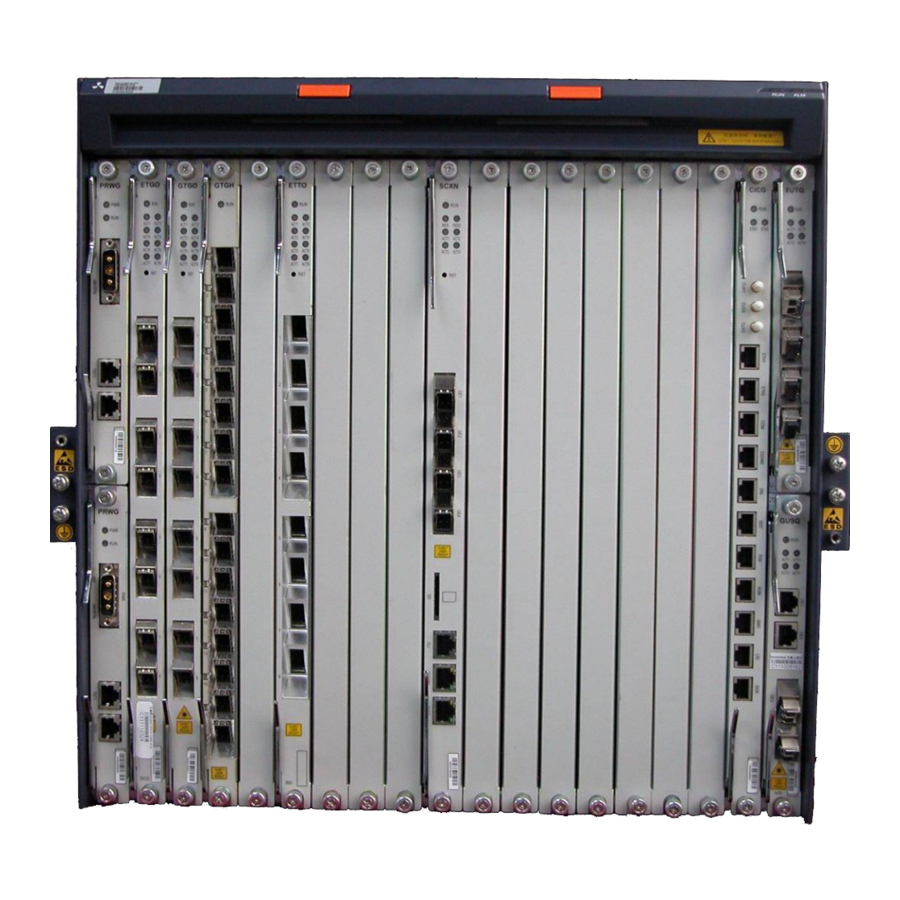
Zte ZXA10 C300 Manuals
Manuals and User Guides for Zte ZXA10 C300. We have
3
Zte ZXA10 C300 manuals available for free PDF download: Configuration Manual, Installation Manual, Maintenance Manual
Zte ZXA10 C300 Configuration Manual (301 pages)
Optical Access Convergence Equipment
Brand:
Zte
| Category:
IP Access Controllers
| Size: 2.89 MB
Table of Contents
Table of Contents
3
About this Manual
9
Chapter 1 Basic Configuration
11
Management Methods
11
Login through Hyperterminal
11
Figure 1-1 Connection Description
12
Figure 1-2 Connect to
12
Login through Telnet
13
Figure 1-3 COM1 Properties
13
Login through NMS
14
Figure 1-4 Run Dialog Box
14
NM Configuration
15
Configuring the In-Band NM
15
Table 1-1 Configuration Data of the In-Band NM
15
Configuring the Out-Of-Band NM
17
Table 1-2 Configuration Data of the Out-Of-Band NM
17
Physical Configuration
18
Adding a Rack
18
Adding a Shelf
19
Adding a Card
20
Table 1-3 Card Configurations for a 19-Inch Shelf
20
Enabling the Pnp Function
21
Table 1-4 Card Configurations for a 21-Inch Shelf
21
Showing Cards
22
Table 1-5 Card Status Description
22
Deleting a Card
23
Resetting a Card
24
Swapping the Active/Standby Switching and Control Cards
24
Configuring Fans
25
System Configuration
26
Configuring the System Time
26
Configuring the Version Auto-Update Function
27
Table 1-6 Configuration Data of Auto-Update Function
27
Configuring the Auto-Backup Function
28
Table 1-7 Configuration Data of Auto-Backup Function
28
Configuring the Auto-Save Function
30
User Management
30
Table 1-8 User Privilege Description
30
Adding a User
31
Table 1-9 User Properties Description
31
Deleting a User
32
Modifying a User
32
Disconnecting an Online User
33
Chapter 2 GPON/XG-PON Service Configuration
35
Figure 2-1 GPON/XG-PON Service Networking Diagram
36
Configuring the GPON ONU Type Profile
37
Table 2-1 Configuration Data of the GPON ONU Type
37
Authenticating the GPON ONU
38
Table 2-2 Configuration Data for GPON ONU Authentication
39
Table 2-3 Descriptions of ONU Phase States
39
Configuring the T-CONT Bandwidth Profile
40
Table 2-4 Parameters of the Default T-CONT Profile
41
Table 2-5 Configuration Data for the T-CONT Profile
41
Configuring the GPON ONU IP Profile
43
Configuring the GPON ONU VLAN Profile
43
Table 2-6 Configuration Data of the GPON ONU IP Profile
43
Configuring the Voip Access Code Profile
44
Table 2-7 Configuration Data of the GPON VLAN Profile
44
Table 2-8 Configuration Data of the Voip Access Code Profile
44
Configuring the Voip Service Application Profile
45
Table 2-9 Configuration Data of the Voip Service Application Profile
45
Configuring the Dial Plan
47
Configuring the GPON SIP Profile
47
Table 2-10 Configuration Data of the GPON SIP Profile
47
Configuring the GPON MGC Profile
48
Table 2-11 Configuration Data of the GPON MGC Profile
49
Configuring the GPON Broadband Service
50
Table 2-12 Configuration Data of the GPON Broadband Service
51
Figure 2-2 Configuration Flowchart of the GPON Broadband Service
52
Configuring the GPON Multicast Service
53
Figure 2-3 Configuration Flowchart of the GPON Multicast Service
55
Configuring the GPON Voice Service (SIP)
57
Table 2-14 Configuration Data of the GPON Voice Service
57
Figure 2-4 Configuration Flowchart of the GPON Voice Service
58
Configuring the GPON Voice Service (H.248)
59
Table 2-15 Configuration Data of the GPON Voice Service
60
Figure 2-5 Configuration Flowchart of the GPON Voice Service
61
Table 3-1 TDM Interface Cards
63
Table 3-2 Value Range of CTLA Interface Parameter
63
Table 3-3 Configuration Data of the GPON CES Service
64
Chapter 3 CES Service Configuration
65
Figure 3-1 Configuration Flowchart of the GPON CES Service
65
Chapter 4 P2P Service Configuration
69
Configuring the P2P Service
69
Table 4-1 P2P Service Configuration Data
70
Chapter 5 VLAN Configuration
73
Configuring the Uplink Port VLAN
73
Table 5-1 VLAN Specifications
73
Configuring the Service Port VLAN
74
Configuring the Cross-Connection VLAN
75
Chapter 6 IPTV Configuration
77
Configuring the IGMP MVLAN
78
Table 6-1 Configuration Data of the IGMP MVLAN
78
Configuring the MLD MVLAN
81
Table 6-2 Configuration Data of the MLD MVLAN
81
Configuring the IPTV Package
83
Table 6-3 Configuration Data of the IPTV Package
83
Configuring the Port IPTV Right
84
Chapter 7 Qos Configuration
87
Ethernet Interface Qos Configuration
87
Configuring the Default Cos
87
Configuring DSCP-Cos Remarking
88
Configuring the Drop Precedence
88
Configuring DSCP Remarking
89
Configuring Queue Scheduling
90
Configuring Traffic Shaping
91
Configuring the Mapping Relation from Cos to Local Queues
92
OLT Interface Qos Configuration
92
Configuring Queue Scheduling
92
Configuring Queue Mapping
93
Configuring the Traffic Profile
93
ONU Interface Qos Configuration
94
Configuring the Trust Precedence
94
Configuring the Default Cos
95
Configuring Cos Remarking
95
Configuring DSCP to Cos Remarking
96
Configuring the Default Egress Cos
96
Configuring Egress Cos Remarking
97
Configuring Egress DSCP to Cos Remarking
97
Configuring Cos Filtering
98
Configuring Queue Scheduling
98
Configuring Queue Mapping
99
Configuring the Traffic Profile
100
Chapter 8 ACL Configuration
101
Configuring a Standard ACL
102
Table 8-1 Configuration Data of the Standard ACL
102
Configuring an Extended ACL
103
Table 8-2 Configuration Data of the Extended ACL
103
Configuring a Layer-2 ACL
104
Table 8-3 Configuration Data of the Layer-2 ACL
105
Configuring a Hybrid ACL
106
Table 8-4 Configuration Data of the Hybrid ACL
106
Configuring an Ipv6 Hybrid ACL
107
Table 8-5 Configuration Data of the Ipv6 Hybrid ACL
108
Chapter 9 NTP Configuration
111
Configuring NTP
111
Chapter 10 STP Configuration
115
Chapter 11 DHCP Configuration
117
Configuring DHCP Snooping
117
Configuring DHCP Server
118
Table 11-1 Configuration Data of DHCP Snooping
118
Table 11-2 Configuration Data of DHCP Server
119
Configuring DHCP Client
120
Table 11-3 Configuration Data of DHCP Client
120
Chapter 12 Uplink Protection Configuration
123
Configuring Link Aggregation
123
Configuring UAPS
127
Configuring CTLA 1+1 Protection
128
Table 13-1 PON Protection Configuration Data
132
Chapter 13 PON Protection Configuration
133
Chapter 14 Access Security Configuration
135
Port Identification Configuration
135
Configuring the Port Identification
135
Table 14-1 Configuration Data of Port Identification
136
Configuring the Dhcpv4 Layer-2 Relay Agent (Dhcpv4L2Ra)
137
Table 14-2 Configuration Data of Dhcpv4L2Ra
137
Configuring the Pppoe Intermediate Agent (Pppoe-IA)
138
Table 14-3 Configuration Data of Pppoe-IA
138
Configuring the Dhcpv6 Layer-2 Relay Agent (Dhcpv6L2Ra)
139
Configuring the NDP Line Identification Option (NDP-LIO)
140
Table 14-4 Configuration Data of Dhcpv6L2Ra
140
Table 14-5 Configuration Data of NDP-LIO
141
MAC Address Anti-Spoofing Configuration
142
Configuring the User Port MAC Address Anti-Spoofing
142
Configuring the Service Gateway MAC Anti-Spoofing
143
Configuring the ARP Anti-Spoofing
144
Configuring the Split Horizon
145
Table 14-6 Configuration Data of ARP Anti-Spoofing
145
Configuring the IP Source Guard
146
Table 14-7 Configuration Data of IP Source Guard
146
Configuring MFF
147
Configuring ARP Proxy
148
Chapter 15 System Security Configuration
149
Configuring SSH
149
Figure 15-1 Quick Connect Dialog Box
150
Configuring TACACS
151
Figure 15-2 SSH Login Window
151
Configuring RADIUS
152
Configuring Management ACL
153
Configuring Control Panel Safety
154
Chapter 16 MPLS Service Configuration
157
MPLS Configuration
157
Configuring the Basic MPLS Function
157
Figure 16-1 Networking Diagram of Basic MPLS Function
158
Table 16-1 Configuration Data of Basic MPLS Function
158
Figure 16-2 Configuration Flowchart of Basic MPLS Function
159
Configuring the Static LSP
161
Figure 16-3 Networking Diagram of Static LSP Configuration
162
Table 16-2 Configuration Data of the Static LSP
162
Figure 16-4 Configuration Flowchart of Static LSP
164
Configuring the LDP FRR Function
168
Figure 16-5 Networking Diagram of LDP FRR Configuration
169
Table 16-3 Configuration Data of the LDP FRR Function
169
Figure 16-6 Configuration Flowchart of LDP FRR Function
171
Configuring the LDP GR Function
175
Figure 16-7 Networking Diagram of LDP GR
175
Table 16-4 Configuration Data of LDP GR Function
175
Figure 16-8 Configuration Flowchart of LDP GR Function
176
VPLS Configuration
179
Configuring the Basic VPLS
179
Figure 16-10 Configuration Flowchart of Basic VPLS
182
Configuring the Full-Mesh VPLS
186
Figure 16-11 Networking Diagram of Full-Mesh VPLS
186
Table 16-6 Configuration Data of Full-Mesh VPLS
187
Figure 16-12 Configuration Flowchart of Full-Mesh VPLS
190
Configuring the Hierarchical VPLS
195
Figure 16-13 HPVLS Networking Diagram
196
Table 16-7 HVPLS Configuration Data
196
Figure 16-14 HVPLS Configuration Flowchart
199
Configuring the VPWS
203
Figure 16-16 Configuration Flowchart of VPWS
206
PWE3 Configuration
210
Configuring the Basic PWE3 Service
210
Figure 16-17 PWE3 Network Reference Model
210
Figure 16-19 Configuration Flowchart of PW Redundancy
213
Configuring Multi-Segment Pws
217
Figure 16-20 Networking Diagram of Multi-Segment Pws
217
Table 16-10 Configuration Data of Multi-Segment Pws
217
Figure 16-21 Configuration Flowchart of Multi-Segment Pws
220
Configuring the TDM Relay Service
224
Figure 16-23 Configuration Flowchart of TDM Relay Service
229
PW Redundancy Configuration
234
Configuring the VPLS Redundancy
234
Figure 16-24 Networking Diagram of VPLS Redundancy
234
Table 16-12 Configuration Data of VPLS Redundancy
235
Figure 16-25 Configuration Flowchart of VPLS Redundancy
237
Configuring the VLL Resilience
243
Figure 16-26 Networking Diagram of VLL Resilience
243
Table 16-13 Configuration Data of VLL Resilience
243
Figure 16-27 Configuration Flowchart of VLL Resilience
246
Configuring the PW Redundancy and BFD
252
Figure 16-28 Networking Diagram of PW Redundancy and BFD
252
Table 16-14 Configuration Data of PW Redundancy and BFD
253
Figure 16-29 Configuration Flowchart of PW Redundancy and BFD
256
Ethernet OAM Configuration
263
Configuring the CCM Function
263
Table 17-1 Configuration Data of CCM Function
263
Chapter 17 OAM Configuration
263
Configuring the LBM Function
265
Table 17-2 Configuration Data of LBM Function
266
Configuring the LTM Function
267
BFD Configuration
269
Configuring the BFD for Static Routes
269
Figure 17-1 BFD Applications
269
Figure 17-2 Networking Diagram of BFD for Static Routes
270
Table 17-3 Configuration Data of BFD for Static Routes
270
Configuring the BFD for VCCV
273
Figure 17-3 Networking Diagram of BFD for VCCV
274
Table 17-4 Configuration Data of BFD for VCCV
274
Chapter 18 Route Protocol Configuration
279
Configuring the Static Route
279
Configuring the OSPF Protocol
279
Configuring the BGP
280
Chapter 19 Clock Configuration
281
Configuring the Synchronous Ethernet Clock
281
Table 19-1 Configuration Data of the Synchronous Ethernet Clock
281
Configuring External Input Clock
283
Configuring the External Output Clock
284
Configuring PTP Slave Clock
286
Figures
289
Glossary
295
Advertisement
Zte ZXA10 C300 Installation Manual (108 pages)
Optical Access Convergence Equipment
Brand:
Zte
| Category:
Touch terminals
| Size: 4.03 MB
Table of Contents
Table of Contents
3
About this Manual
7
Chapter 1 Overview
7
Cabinet Introduction
11
Cabinet Features
12
Figure 1-1 Cabinet Appearance
12
Figure 1-2 Cabinet Appearance
12
Equipment Configuration
13
Cabinet Configuration
13
Shelf Configuration
14
Figure 1-3 Cabinet Configuration for 19-Inch Shelves
14
Figure 1-4 19-Inch Shelf Structure
15
Figure 1-5 19-Inch Shelf Structure
15
Cards
16
Figure 1-6 19-Inch Shelf Configuration
16
Table 1-1 19-Inch Shelf Technical Specifications
16
Table 1-2 Card List
16
System Components
17
Technical Standards
18
Table 1-3 Technical Standards
18
Technical Specifications
20
Performance Specifications
21
Table 1-4 Reliability and Security Specifications
21
Chapter 2 Pre-Installation Preparation
23
Installation Preparation Flow
23
Engineering Documents Preparation
24
Figure 2-1 Installation Preparation Flow
24
Tools and Meters
25
Installation Environment Check
26
Construction Check
26
Indoor Environment Check
26
Table 2-1 Operation Environment Requirements
26
Power Supply Check
27
Grounding Cable Check
28
Security Check
28
Other Supporting Facilities Check
28
Unpacking
29
Unpacking Cabinet
29
Figure 2-2 Packing Box
30
Figure 2-3 Cabinet Inner Package
31
Unpacking Shelf
32
Figure 2-4 Shelf Packing Box
32
Unpacking Cards
33
Figure 2-5 Card Packing Box
33
Figure 2-6 Opened Card Packing Box
34
Chapter 3 Cabinet Installation
35
Cabinet Installation Flowchart
35
Base Installation Mode
36
Base Structure
36
Figure 3-1 Cabinet Installation Flowchart
36
Figure 3-2 Cabinet Base Structure
37
Figure 3-3 Base with Adjustable Height from 160 MM to 260 MM
37
Figure 3-4 Base with Adjustable Height from 260 MM to 460 MM
38
Figure 3-5 Base with Adjustable Height from 460 MM to 660 MM
38
Base Installation Flowchart
39
Positioning Base
39
Figure 3-6 Base Installation Flowchart
39
Figure 3-7 Drilling Diagram
40
Installing Base
41
Fixing Cabinet
41
Figure 3-8 Installing Base
41
Figure 3-9 Fixing Cabinet
42
Foot Installation Mode
43
Foot Installation Flowchart
43
Figure 3-10 Cabinet Installed on the Base
43
Positioning Cabinet
44
Figure 3-11 Foot Installation Flowchart
44
Figure 3-12 Drilling Diagram
45
Installing Expansion Bolt
46
Fixing Cabinet
46
Figure 3-13 Cabinet Installation Holes
47
Cabinets Connection
48
Cabinets Connection in Base Installation Mode
48
Figure 3-14 Fixing Cabinet
48
Figure 3-15 Fixing Two Cabinets in Parallel
49
Cabinets Connection in Foot Installation Mode
50
Figure 3-16 Fixing Multiple Cabinets in Parallel
50
Figure 3-17 Fixing Two Cabinets in Parallel
51
Adjacent Cabinets Connection
52
Figure 3-18 Fixing Multiple Cabinets in Parallel
52
Shelf Installation
53
Figure 3-19 Connecting Adjacent Cabinets
53
Plug-In Box Installation
54
Figure 3-20 Installing Shelf
54
Card Installation
55
Figure 3-21 Installing Plug-In Box
55
Chapter 4 Power Supply Installation
57
Power and Grounding Cables
57
Power and Grounding Cable Structure
58
Figure 4-1 Power and Grounding Cables Installation Flowchart
58
Figure 4-2 -48 V Power Cable Structure
59
Figure 4-3 Internal Power Cable Structure
59
Table 4-1 Internal Power Cable Pin Connections
59
Power and Grounding Cable Installation
60
19-Inch Power Distributor
60
Figure 4-4 Protection Grounding Cable Structure
60
Figure 4-5 19-Inch Power Distributor Dimensions
61
48 V Input Power Cable Installation
62
Figure 4-6 Power Distributor Internal Structure
62
Internal Power Cable Installation
63
Figure 4-7 Power Distributor Cable Connections
63
Grounding Cable Installation
64
Figure 4-8 Internal Power Cable Layout
64
Figure 4-9 Cabinet Grounding Point
65
Figure 4-10 Protection Ground Connection
66
Chapter 5 Cable Connection
67
Overall Cabling
67
Cable Layout
68
Cabling Principles
68
Figure 5-1 Uplink Cabling
68
Cable Bundling
69
Figure 5-2 Cables Bundling
70
Figure 5-3 Tie Cutting
70
Figure 5-4 Tie Space
71
Figure 5-5 Cable Tie Position
71
E1/T1 Cable
72
Figure 5-6 Cabling Technique in Cabinet
72
Figure 5-7 E1 Cable Structure
73
Table 5-1 E1 Cable Pin Connections
73
Figure 5-8 T1 Cable Structure
74
Table 5-2 T1 Cable Pin Connections
75
Monitoring Cables
76
Entrance Control Monitoring Cable
77
Figure 5-9 Monitoring Cable Routing
77
Smog Monitoring Cable
78
Figure 5-10 Entrance Control Monitoring Cable Structure
78
Table 5-3 Entrance Control Monitoring Cable Pin Connections
78
Flood Monitoring Cable
79
Figure 5-11 Smog Monitoring Cable Structure
79
Table 5-4 Smog Monitoring Cable Pin Connections
79
Temperature Monitoring Cable
80
Figure 5-12 Flood Monitoring Cable Structure
80
Table 5-5 Flood Monitoring Cable Pin Connections
80
Humidity Monitoring Cable
81
Figure 5-13 Temperature Monitoring Cable Structure
81
Table 5-6 Temperature Monitoring Cable Pin Connections
81
Serial Port Cable
82
Figure 5-14 Humidity Monitoring Cable Structure
82
Table 5-7 Humidity Monitoring Cable Pin Connections
82
Figure 5-15 Serial Port Cable Structure
83
Table 5-8 Serial Port Cable Connections
83
Network Cable
84
Figure 5-16 Network Cable Structure
84
Optical Fiber
85
Table 5-9 Relationship between Network Cables and Core Cables
85
Chapter 6 Installation Check
87
Overall Inspection
87
Power-ON/OFF Inspection
88
Inspection before Power-ON
88
Power-ON Process
89
Power-OFF Process
90
Appendix A Indoor Cabinet Grounding System Connection
91
Overview
91
Central Office Cabinet Grounding
91
Remote Office Cabinet Grounding
93
Figure A-3 Remote Office Cabinet Grounding
94
Appendix B Grounding Network Requirements
95
Table B-1 Length and Cross-Sectional Area Requirements
95
Cabinet and Central Office
96
Outgoing/Incoming Cables From/To Central Office
96
Appendix C Lightning Proof Network
99
Lightning Requirements
99
Lightning Design
99
Table C-1 Lightning Protection Level
99
Table C-2 Lightning Protection Device Parameters
99
Lightning Protection Grounding in Central Office
100
Lightning Protection Grounding in Remote Office
100
Figures
103
Glossary
107
Zte ZXA10 C300 Maintenance Manual (75 pages)
GPON Optical Access Convergence Equipment
Brand:
Zte
| Category:
Network Hardware
| Size: 1.45 MB
Table of Contents
Table of Contents
3
About this Manual
5
Chapter 1 Safety Descriptions
7
Safety Precautions
7
Sign Descriptions
8
Chapter 2 Routine Maintenance
11
Routine Maintenance Precautions
11
Equipment Routine Maintenance
12
Environment Check
12
Equipment Status Check
13
Switching and Control Card Running Status Check
15
PON Interface Card Running Status Check
16
Ethernet Uplink Card Running Status Check
18
Ethernet Interface Card Running Status Check
21
P2P Interface Card Running Status Check
22
TDM Interface Card Running Status Check
22
Common Interface Card Running Status Check
24
Power Interface Card Running Status Check
24
NMS Routine Maintenance
25
Monitoring Alarms in Real Time
25
Checking NE Data Backup Status
29
Monitoring NMS Performance
31
Detecting Virus
35
Chapter 3 Data Backup and Recovery
39
NE Data Saving
39
Saving NE Data in Real Time
39
Saving NE Data Periodically
40
NE Data Backup
43
Backing up NE Data in Real Time
43
Backing up NE Data Periodically
44
Restoring NE Data
47
Performing Active/Standby Card Changeover
48
Chapter 4 Expansion Guides
51
Chapter 5 Cutover Guides
53
Chapter 6 Version Upgrade Guides
57
Overview
57
Version Information
57
Upgrading Precautions
58
Upgrading Tools
58
Upgrading Preparations
58
Upgrading Versions
61
Upgrade Versions
62
Upgrading Patches
63
Testing Upgrading Results
65
Processing Guides for Upgrade Failure
66
Appendix A Card Replacement
67
Replacing Switching and Control Card
67
Replacing Other Cards
70
Glossary
75
Advertisement
Advertisement
Related Products
Zte ZXA10 C320
Zte ZXA10 F660
ZTE ZXA10 S300
Zte ZXR10 2600
Zte ZXR10 2900 Series
Zte ZXR10 5250-52PM
Zte ZXR10 2900E Series
Zte ZXV10 W300
Zte ZXG10-OB06
Zte ZXR10 8912
Zte Categories
Cell Phone
Modem
Wireless Router
Network Router
Switch
More Zte Manuals
Login
Sign In
OR
Sign in with Facebook
Sign in with Google
Upload manual
Upload from disk
Upload from URL