Zte ZXA10 C300 Installation Manual
Optical access convergence equipment
Hide thumbs
Also See for ZXA10 C300:
- Maintenance manual (75 pages) ,
- Configuration manual (301 pages) ,
- Manual (87 pages)
Table of Contents
Advertisement
Advertisement
Table of Contents

Related Manuals for Zte ZXA10 C300


Summary of Contents for Zte ZXA10 C300
- Page 1 ZXA10 C300 Optical Access Convergence Equipment Cabinet Installation Guide (19 Inch) Version: V1.2.1 ZTE CORPORATION NO. 55, Hi-tech Road South, ShenZhen, P.R.China Postcode: 518057 Tel: +86-755-26771900 Fax: +86-755-26770801 URL: http://ensupport.zte.com.cn E-mail: support@zte.com.cn...
- Page 2 ZTE CORPORATION is prohibited. Additionally, the contents of this document are protected by contractual confidentiality obligations. All company, brand and product names are trade or service marks, or registered trade or service marks, of ZTE CORPORATION or of their respective owners.
-
Page 3: Table Of Contents
Contents About This Manual ..................I Chapter 1 Overview ..................1-1 1.1 Cabinet Introduction ................... 1-1 1.2 Cabinet Features....................1-2 1.3 Equipment Configuration ..................1-3 1.3.1 Cabinet Configuration ................1-3 1.3.2 Shelf Configuration................... 1-4 1.3.3 Cards ...................... 1-6 1.4 System Components ..................1-7 1.5 Technical Standards ................... - Page 4 3.2.4 Installing Base ..................3-7 3.2.5 Fixing Cabinet..................3-7 3.3 Foot Installation Mode ..................3-9 3.3.1 Foot Installation Flowchart ................ 3-9 3.3.2 Positioning Cabinet ................3-10 3.3.3 Installing Expansion Bolt................. 3-12 3.3.4 Fixing Cabinet..................3-12 3.4 Cabinets Connection ..................3-14 3.4.1 Cabinets Connection in Base Installation Mode ........
- Page 5 5.7 Optical Fiber ....................5-19 Chapter 6 Installation Check ..............6-1 6.1 Overall Inspection ....................6-1 6.2 Power-ON/OFF Inspection .................. 6-2 6.2.1 Inspection before Power-ON ..............6-2 6.2.2 Power-ON Process................... 6-3 6.2.3 Power-OFF Process ................. 6-4 Appendix A Indoor Cabinet Grounding System Connection ....A-1 A.1 Overview ......................
-
Page 7: About This Manual
The ZXA10 C300 can be connected with MDUs/ONUs/ONTs through various networking technologies. The ZXA10 C300 device consists of the switching and control cards, PON interface cards, uplink cards, Ethernet interface card, P2P interface cards, TDM interface cards, and common interface card. It provides large-capacity controllable multicast and high QoS control. - Page 8 (station) cable requirements. Appendix C, Lighting Proof Network Describes the lightning protection requirements and lightening protection design. Conventions ZTE documents employ the following typographical conventions. Typeface Meaning Italics References to other Manuals and documents. “Quotes”...
- Page 9 Typeface Meaning Click Refers to clicking the primary mouse button (usually the left mouse button) once. Double-click Refers to quickly clicking the primary mouse button (usually the left mouse button) twice. Right-click Refers to clicking the secondary mouse button (usually the right mouse button) once.
-
Page 11: Cabinet Introduction
Technical Specifications ...................1-10 Performance Specifications ..................1-11 1.1 Cabinet Introduction According to different shelf sizes, ZXA10 C300 uses 19-inch indoor cabinets B6030-22C-IB and B6060-22F, and 21-inch indoor cabinet B6030-22C-EB. Each cabinet can hold two ZXA10 C300 shelves. This manual introduces 19-inch cabinets. -
Page 12: Cabinet Features
ZXA10 C300 Cabinet Installation Guide (19 Inch) Figure 1-1 Cabinet Appearance Figure 1-2 shows the B6060-22F cabinet appearance. Figure 1-2 Cabinet Appearance 1.2 Cabinet Features The B6030-22C-IB and B6060-22F cabinets are applicable to the areas where there are a large number of users and there are equipment rooms. -
Page 13: Equipment Configuration
Complete monitoring functions High anti-interference capability Good ventilation Nice appearance 1.3 Equipment Configuration This section includes the following: Cabinet Configuration Shelf Configuration Cards 1.3.1 Cabinet Configuration Figure 1-3 shows the cabinet configuration for the 19-inch shelves. SJ-20110909101511-005|2011-12-31 (R1.1) ZTE Proprietary and Confidential... -
Page 14: Shelf Configuration
ZXA10 C300 Cabinet Installation Guide (19 Inch) Figure 1-3 Cabinet Configuration for 19-Inch Shelves 1.3.2 Shelf Configuration Shelf Structure When the 19-inch shelf is installed in a B6030-22C-IB cabinet, its structure is as shown in Figure 1-4. SJ-20110909101511-005|2011-12-31 (R1.1) ZTE Proprietary and Confidential... -
Page 15: Figure 1-4 19-Inch Shelf Structure
Figure 1-4 19-Inch Shelf Structure When the 19-inch shelf is installed in a B6060-22F cabinet, its structure is as shown in Figure 1-5. Figure 1-5 19-Inch Shelf Structure Shelf Configuration Figure 1-6 shows the 19-inch shelf configuration. SJ-20110909101511-005|2011-12-31 (R1.1) ZTE Proprietary and Confidential... -
Page 16: Cards
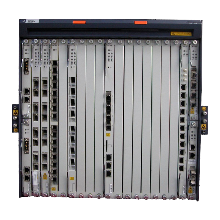
443.7 mm × 482.6 mm × 270 mm (Height × Width × Depth) Weight 12.5 kg (Empty) 34.2 kg (Full configuration) 1.3.3 Cards The ZXA10 C300 shelf consists of cards and a fan module, as listed in Table 1-2. Table 1-2 Card List Card Type... -
Page 17: System Components
Fan module FAN-C300 Fan module 1.4 System Components The ZXA10 C300 cabinet consists of the following components: Power Supply Module The equipment room provides -48 V power for the cabinet. The PRWG power card provides the secondary power to all the interface cards. -
Page 18: Technical Standards
ZXA10 C300 Cabinet Installation Guide (19 Inch) Fan Module Fan module is a box, which is 1U in height and 19 inches in width. Wiring Area The wiring area holds an independent wiring plug-in box. It provides an area for wiring and a dust-proof net. - Page 19 Electronic and Electric Products Application Environment Conditions, Transportation GIB-Z35-93 Component Derating Rules GJB450-88 General Guideline for Equipment Research and Production Reliability GJB-299A-91 Prediction Manual for Electric Equipment Reliability ANSI/IEEE Std 802.1D Media Access Control (MAC) Network Bridge (1998) SJ-20110909101511-005|2011-12-31 (R1.1) ZTE Proprietary and Confidential...
-
Page 20: Technical Specifications
ZXA10 C300 Cabinet Installation Guide (19 Inch) Standard No. Standard Name ITU-T G.703 Physical/Electrical Characteristics of Series Digital Interfaces ITU-T G.704 Structure of All Synchronization Frames of Primary Group Rate and Secondary Group Rate Series ITU-T G.960 Digital Segment for ISDN Basic Access ITU-T G.961... -
Page 21: Performance Specifications
The equipment power consumption is as follows: Cabinet with full configuration: 2800 W A single shelf: 1400 W 1.7 Performance Specifications Table 1-4 lists the ZXA10 C300 reliability and security specifications. Table 1-4 Reliability and Security Specifications Item Specification Static anti-interference... - Page 22 ZXA10 C300 Cabinet Installation Guide (19 Inch) This page intentionally left blank. 1-12 SJ-20110909101511-005|2011-12-31 (R1.1) ZTE Proprietary and Confidential...
-
Page 23: Chapter 2 Pre-Installation Preparation
Chapter 2 Pre-Installation Preparation Table of Contents Installation Preparation Flow ..................2-1 Engineering Documents Preparation ................2-2 Tools and Meters......................2-3 Installation Environment Check ..................2-4 Unpacking ........................2-7 2.1 Installation Preparation Flow Figure 2-1 shows the installation preparation flow. SJ-20110909101511-005|2011-12-31 (R1.1) ZTE Proprietary and Confidential... -
Page 24: Engineering Documents Preparation
The following documents are related to ZXA10 C300: Purchase contract (duplicate copy) and technical proposals. Engineering survey report, environment acceptance report, and installation acceptance report. ZXA10 C300 (V1.2) EPON/10G EPON Optical Access Convergence Equipment Hardware Installation Manual SJ-20110909101511-005|2011-12-31 (R1.1) ZTE Proprietary and Confidential... -
Page 25: Tools And Meters
Optical attenuator Tip: All the tools and meters must be calibrated in advance. The general tools and meters are usually provided by the customer. ZTE installation engineers usually bring the special tools and meters with them. SJ-20110909101511-005|2011-12-31 (R1.1) ZTE Proprietary and Confidential... -
Page 26: Installation Environment Check
ZXA10 C300 Cabinet Installation Guide (19 Inch) 2.4 Installation Environment Check This topic includes the following: Construction Check Indoor Environment Check Power Supply Check Grounding Cable Check Security Check Other Supporting Facilities Check 2.4.1 Construction Check Implement the following construction checks: Check civil work and make sure that indoor walls are dry. -
Page 27: Power Supply Check
The power cables should be clearly separated from the signal lines and subscriber lines. In the process of laying out the power cables, make sure that the feed cables and busbar meet the medium-term or long-term expansion demands. SJ-20110909101511-005|2011-12-31 (R1.1) ZTE Proprietary and Confidential... -
Page 28: Grounding Cable Check
ZXA10 C300 Cabinet Installation Guide (19 Inch) 2.4.4 Grounding Cable Check This topic describes the grounding requirements and factors affecting grounding. Grounding Requirements Grounding cables must meet the following requirements: Lay out the grounding cables in the equipment room in radial or plane mode. Use separate cables for the DC power distribution system protection grounding, working grounding, and lightning protection grounding. -
Page 29: Unpacking
1. Count the total number of the goods. Before unpacking, it is necessary to count the number of the goods according to the packing list attached to the packing boxes. It is recommended to keep a record of goods. SJ-20110909101511-005|2011-12-31 (R1.1) ZTE Proprietary and Confidential... -
Page 30: Figure 2-2 Packing Box
ZXA10 C300 Cabinet Installation Guide (19 Inch) 2. Unpack the cabinet box. Caution! Be cautious while unpacking. Protect the equipment coating and the circuit boards. When the equipment arrives at the destination with a considerably different temperature and humidity, do not open the package until it stays for some time in order to avoid damage to the equipment. -
Page 31: Figure 2-3 Cabinet Inner Package
Make sure that cabinet interior is clean with reliable socket connection and clear markings. Because the plug-in units are transported with the cabinet, their reinforcing mode, SJ-20110909101511-005|2011-12-31 (R1.1) ZTE Proprietary and Confidential... -
Page 32: Unpacking Shelf
ZXA10 C300 Cabinet Installation Guide (19 Inch) installation accessories, and reliability should be checked carefully. Close the cabinet door when completing the cabinet inspection. – End of Steps – Result The cabinet is successfully unpacked. 2.5.2 Unpacking Shelf Perform this procedure to unpack the shelf. -
Page 33: Unpacking Cards
Fill in the acceptance list and the acceptance report. Both parties should sign for confirmation and each party should keep a copy. Contact the local ZTE office, if anything is found damaged, wrong, or missing during the unpacking inspection. 2.5.3 Unpacking Cards Perform this procedure to unpack cards. -
Page 34: Figure 2-6 Opened Card Packing Box
Fill in the acceptance list and the acceptance report. Both parties should sign it for confirmation and each party should keep a copy. Contact the local ZTE office, if anything is found damaged, wrong, or missing during the unpacking inspection. -
Page 35: Chapter 3 Cabinet Installation
Plug-in Box Installation .....................3-20 Card Installation .......................3-21 3.1 Cabinet Installation Flowchart Confirm the location of the cabinet according to the ZXA10 C300 (V1.2) Optical Access Convergence Equipment Project Survey Report before installing the cabinet. The cabinet can be installed in the following modes:... -
Page 36: Base Installation Mode
ZXA10 C300 Cabinet Installation Guide (19 Inch) Figure 3-1 Cabinet Installation Flowchart 3.2 Base Installation Mode Base installation mode is to install the cabinet with a base. This topic includes the following: Base Structure Base Installation Flowchart Positioning Base Installing Base Fixing Cabinet 3.2.1 Base Structure... -
Page 37: Figure 3-2 Cabinet Base Structure
160 mm to 260 mm. Figure 3-3 Base With Adjustable Height From 160 mm to 260 mm Figure 3-4 shows the base whose height is adjustable from 260 mm to 460 mm. SJ-20110909101511-005|2011-12-31 (R1.1) ZTE Proprietary and Confidential... -
Page 38: Figure 3-4 Base With Adjustable Height From 260 Mm To 460 Mm
ZXA10 C300 Cabinet Installation Guide (19 Inch) Figure 3-4 Base With Adjustable Height From 260 mm to 460 mm Figure 3-5 shows the base whose height is adjustable from 460 mm to 660 mm. Figure 3-5 Base With Adjustable Height From 460 mm to 660 mm SJ-20110909101511-005|2011-12-31 (R1.1) -
Page 39: Base Installation Flowchart
Use a measuring tape to measure the position. c. Use an ink marker to mark the position. Figure 3-7 shows the drilling diagram. SJ-20110909101511-005|2011-12-31 (R1.1) ZTE Proprietary and Confidential... -
Page 40: Figure 3-7 Drilling Diagram
ZXA10 C300 Cabinet Installation Guide (19 Inch) Figure 3-7 Drilling Diagram 2. Drilling a. Drill holes at the positions where the expansion bolt holes are marked. b. Keep the drill bit vertical to the ground and tightly hold the handle. -
Page 41: Installing Base
The following steps are required for fixing a cabinet: 1. Move the cabinet on to the base. 2. Use the foot under the base to adjust the level. 3. Fix the cabinet on the base, as shown in Figure 3-9. SJ-20110909101511-005|2011-12-31 (R1.1) ZTE Proprietary and Confidential... -
Page 42: Figure 3-9 Fixing Cabinet
ZXA10 C300 Cabinet Installation Guide (19 Inch) Figure 3-9 Fixing Cabinet 1. Cabinet 3. Spring washer 12 6. Adjustable base 2. Hex head screw M12 4. Washer × 40 5. Cabinet bottom Figure 3-10 shows the cabinet that is successfully installed on the base. -
Page 43: Foot Installation Mode
Foot installation mode is to install the cabinet on the ground directly. This topic includes the following: Foot Installation Flowchart Positioning Cabinet Installing Expansion Bolt Fixing Cabinet 3.3.1 Foot Installation Flowchart Figure 3-11 shows the foot installation flowchart. SJ-20110909101511-005|2011-12-31 (R1.1) ZTE Proprietary and Confidential... -
Page 44: Positioning Cabinet
ZXA10 C300 Cabinet Installation Guide (19 Inch) Figure 3-11 Foot Installation Flowchart 3.3.2 Positioning Cabinet Two steps are required for positioning the cabinet. 1. Marking a. Confirm the position for installing the cabinet according to the reference dimensions and base dimensions given in the engineering design diagram. -
Page 45: Figure 3-12 Drilling Diagram
While drilling, use a cleaner to remove dust. If the surface is too smooth and solid to locate the drill bit, cut a concave with a punching bit to help position the drill bit. 3-11 SJ-20110909101511-005|2011-12-31 (R1.1) ZTE Proprietary and Confidential... -
Page 46: Installing Expansion Bolt
ZXA10 C300 Cabinet Installation Guide (19 Inch) Caution! Marking and drilling are important for hardware installation. Improper marking and drilling may cause much inconvenience in the future work. The quality of marking and drilling is the prerequisite to the whole project. -
Page 47: Figure 3-13 Cabinet Installation Holes
Chapter 3 Cabinet Installation Figure 3-13 Cabinet Installation Holes 2. Fix the cabinet on the cement floor, as shown in Figure 3-14. 3-13 SJ-20110909101511-005|2011-12-31 (R1.1) ZTE Proprietary and Confidential... -
Page 48: Cabinets Connection
ZXA10 C300 Cabinet Installation Guide (19 Inch) Figure 3-14 Fixing Cabinet 1. Cabinet 4. Insulation washer 7. Cement floor 2. Bolt M12 × 90 5. Cabinet bottom 3. Washer 6. Insulation plate 3.4 Cabinets Connection This topic includes the following:... -
Page 49: Figure 3-15 Fixing Two Cabinets In Parallel
Figure 3-15 Fixing Two Cabinets In Parallel 1. Inner wall 3. Holes drilled on the ground 2. Cabinet edge 4. Cabinet edge Fixing Multiple Cabinets Fix multiple cabinets in parallel, as shown in Figure 3-16. 3-15 SJ-20110909101511-005|2011-12-31 (R1.1) ZTE Proprietary and Confidential... -
Page 50: Cabinets Connection In Foot Installation Mode
ZXA10 C300 Cabinet Installation Guide (19 Inch) Figure 3-16 Fixing Multiple Cabinets In Parallel 1. Inner wall 3. Holes drilled on the ground 2. Cabinet edge 4. Cabinet edge 3.4.2 Cabinets Connection in Foot Installation Mode Fixing Two Cabinets Fix two cabinets in parallel, as shown in Figure 3-17. -
Page 51: Figure 3-17 Fixing Two Cabinets In Parallel
Figure 3-17 Fixing Two Cabinets In Parallel 1. Inner wall 3. Holes drilled on the ground 2. Cabinet edge 4. Cabinet edge Fixing Multiple Cabinets Fix multiple cabinets in parallel, as shown in Figure 3-18. 3-17 SJ-20110909101511-005|2011-12-31 (R1.1) ZTE Proprietary and Confidential... -
Page 52: Adjacent Cabinets Connection
ZXA10 C300 Cabinet Installation Guide (19 Inch) Figure 3-18 Fixing Multiple Cabinets In Parallel 1. Inner wall 3. Holes drilled on the ground 2. Cabinet edge 4. Cabinet edge 3.4.3 Adjacent Cabinets Connection When two or more than two cabinets are placed one by one, it is necessary to connect... -
Page 53: Shelf Installation
Make sure that the screws and connecting cables are fixed. If the shelf is packed separately, it is necessary to install the shelf. Figure 3-20 shows how to install a shelf in a cabinet. 3-19 SJ-20110909101511-005|2011-12-31 (R1.1) ZTE Proprietary and Confidential... -
Page 54: Plug-In Box Installation
ZXA10 C300 Cabinet Installation Guide (19 Inch) Figure 3-20 Installing Shelf 1. Nut 3. Shelf 5. Cabinet 2. Panel combined screw 4. Brackets 3.6 Plug-in Box Installation Plug-in box refers to the components such as the fan box, wiring box, and blank panel. -
Page 55: Card Installation
3. Press claspers on the card and push it in until it is latched, which means the card is in place. On the back of each shelf, there are floating grounding spring plates, which enable all cards to be grounded. 3-21 SJ-20110909101511-005|2011-12-31 (R1.1) ZTE Proprietary and Confidential... - Page 56 ZXA10 C300 Cabinet Installation Guide (19 Inch) Installing Dummy Panel Install dummy panels in empty slots. The spring plate at the back of the dummy panel is used to adjust the tightness. 3-22 SJ-20110909101511-005|2011-12-31 (R1.1) ZTE Proprietary and Confidential...
-
Page 57: Chapter 4 Power Supply Installation
Power cables include the following: -48 V input power cables Power cables inside the cabinet Grounding cables are cabinet protection cables. 4.2 Installation Flowchart Figure 4-1 shows the power and grounding cables installation flowchart. SJ-20110909101511-005|2011-12-31 (R1.1) ZTE Proprietary and Confidential... -
Page 58: Power And Grounding Cable Structure
ZXA10 C300 Cabinet Installation Guide (19 Inch) Figure 4-1 Power and Grounding Cables Installation Flowchart 4.3 Power and Grounding Cable Structure -48 V Input Power Cable Figure 4-2 shows the -48 V input power cables structure. SJ-20110909101511-005|2011-12-31 (R1.1) ZTE Proprietary and Confidential... -
Page 59: Figure 4-2 -48 V Power Cable Structure
Table 4-1 Internal Power Cable Pin Connections End A (Connects to Power Cable Color Signal Description End B (Connects to Power Card) Spectrum/Heat Power Distributor) Shrinkage Bush Black/Blue Bush -48 V SJ-20110909101511-005|2011-12-31 (R1.1) ZTE Proprietary and Confidential... -
Page 60: Power And Grounding Cable Installation
ZXA10 C300 Cabinet Installation Guide (19 Inch) End A (Connects to Power Cable Color Signal Description End B (Connects to Power Card) Spectrum/Heat Power Distributor) Shrinkage Bush Black/Without Bush -48 VRTN Protection Grounding Cable Figure 4-4 shows the protection grounding cable structure. -
Page 61: Figure 4-5 19-Inch Power Distributor Dimensions
Chapter 4 Power Supply Installation Figure 4-5 19-Inch Power Distributor Dimensions 1. Installation bracket 2. Box bottom 3. Box cover Internal Structure Figure 4-6 shows the power distributor internal structure. SJ-20110909101511-005|2011-12-31 (R1.1) ZTE Proprietary and Confidential... -
Page 62: 48 V Input Power Cable Installation
ZXA10 C300 Cabinet Installation Guide (19 Inch) Figure 4-6 Power Distributor Internal Structure 1. Connection terminal 4. Central short circuit plate 5. 2-core transfer connector 2. Central short circuit plate for two screws with an unit 3. 50 A unipolar small breaker internal spacing of 15.2 mm... -
Page 63: Internal Power Cable Installation
Chapter 4 Power Supply Installation Figure 4-7 Power Distributor Cable Connections 4.4.3 Internal Power Cable Installation Figure 4-8 shows the power cable layout inside the cabinet. SJ-20110909101511-005|2011-12-31 (R1.1) ZTE Proprietary and Confidential... -
Page 64: Grounding Cable Installation
ZXA10 C300 Cabinet Installation Guide (19 Inch) Figure 4-8 Internal Power Cable Layout 4.4.4 Grounding Cable Installation The cabinet grounding point is at the top of the cabinet, as shown in Figure 4-9. SJ-20110909101511-005|2011-12-31 (R1.1) ZTE Proprietary and Confidential... -
Page 65: Figure 4-9 Cabinet Grounding Point
Chapter 4 Power Supply Installation Figure 4-9 Cabinet Grounding Point Connect the protection ground from the grounding busbar in the equipment room to the grounding point at the top of the cabinet, as shown in Figure 4-10. SJ-20110909101511-005|2011-12-31 (R1.1) ZTE Proprietary and Confidential... -
Page 66: Figure 4-10 Protection Ground Connection
ZXA10 C300 Cabinet Installation Guide (19 Inch) Figure 4-10 Protection Ground Connection 4-10 SJ-20110909101511-005|2011-12-31 (R1.1) ZTE Proprietary and Confidential... -
Page 67: Chapter 5 Cable Connection
Table of Contents Overall Cabling......................5-1 Cable Layout ......................5-2 E1/T1 Cable .......................5-6 Monitoring Cables ....................5-10 Serial Port Cable ......................5-16 Network Cable......................5-18 Optical Fiber......................5-19 5.1 Overall Cabling Figure 5-1 shows the uplink cabling in the cabinet. SJ-20110909101511-005|2011-12-31 (R1.1) ZTE Proprietary and Confidential... -
Page 68: Cable Layout
ZXA10 C300 Cabinet Installation Guide (19 Inch) Figure 5-1 Uplink Cabling 5.2 Cable Layout This topic includes the following: Cabling Principles Cable Bundling 5.2.1 Cabling Principles The basic principles for cabling are as follows: SJ-20110909101511-005|2011-12-31 (R1.1) ZTE Proprietary and Confidential... -
Page 69: Cable Bundling
5.2.2 Cable Bundling Cable Binding Technique Bundle cables in sequence. Avoid bending the cables. Figure 5-2 shows the cables bundling technique. Keep cables vertical to the ground. Bind cables with a tie at an equal distance. SJ-20110909101511-005|2011-12-31 (R1.1) ZTE Proprietary and Confidential... -
Page 70: Figure 5-2 Cables Bundling
ZXA10 C300 Cabinet Installation Guide (19 Inch) Figure 5-2 Cables Bundling Tie Cutting Technique Cut the tie head smoothly. Figure 5-3 shows the tie cutting technique. The tick mark shows a correct cutting while the cross mark shows an incorrect cutting. -
Page 71: Figure 5-4 Tie Space
Chapter 5 Cable Connection Figure 5-4 Tie Space Tie Position Keep ties at the correct positions, as shown in Figure 5-5. Figure 5-5 Cable Tie Position 1. Cable tie Figure 5-6 shows the cabling technique in cabinet. SJ-20110909101511-005|2011-12-31 (R1.1) ZTE Proprietary and Confidential... -
Page 72: E1/T1 Cable
ZXA10 C300 Cabinet Installation Guide (19 Inch) Figure 5-6 Cabling Technique In Cabinet 5.3 E1/T1 Cable The E1 cable is used to connect the CTBB card to the PSTN network. The T1 cable is used to connect the CTTB card to the PSTN network. -
Page 73: Figure 5-7 E1 Cable Structure
Grey (Red1) Grey (Black1) Grey (Black1) Blue (Red2) Blue (Red2) Blue (Black2) Blue (Black2) Pink (Red2) Pink (Red2) Pink (Black2) Pink (Black2) Green (Red2) Green (Red2) Green (Black2) Green (Black2) Orange (Red2) Orange (Red2) SJ-20110909101511-005|2011-12-31 (R1.1) ZTE Proprietary and Confidential... -
Page 74: Figure 5-8 T1 Cable Structure
ZXA10 C300 Cabinet Installation Guide (19 Inch) Pin No. at End Cable Color Pin No. at End Cable Color Spectrum B1 Spectrum B2 Orange (Black2) Orange (Black2) Grey (Red2) Grey (Red2) Grey (Black2) Grey (Black2) Blue (Red3) Blue (Red3) Blue (Black3) -
Page 75: Table 5-2 T1 Cable Pin Connections
Pink (Red3) Pink (Black3) Pink (Black3) Green (Red3) Green (Red3) Green (Black3) Green (Black3) Orange (Red3) Orange (Red3) Orange (Black3) Orange (Black3) Grey (Red3) Grey (Red3) Grey (Black3) Grey (Black3) Blue (Red4) Blue (Red4) SJ-20110909101511-005|2011-12-31 (R1.1) ZTE Proprietary and Confidential... -
Page 76: Monitoring Cables
ZXA10 C300 Cabinet Installation Guide (19 Inch) Pin No. at End Cable Color Pin No. at End Cable Color Spectrum B1 Spectrum B2 Blue (Black4) Blue (Black4) 5.4 Monitoring Cables Monitoring cables include the following: Entrance control monitoring cable Smog monitoring cable... -
Page 77: Entrance Control Monitoring Cable
Chapter 5 Cable Connection Figure 5-9 Monitoring Cable Routing 5.4.1 Entrance Control Monitoring Cable Cable Structure Figure 5-10 shows the entrance control monitoring cable structure. 5-11 SJ-20110909101511-005|2011-12-31 (R1.1) ZTE Proprietary and Confidential... -
Page 78: Smog Monitoring Cable
ZXA10 C300 Cabinet Installation Guide (19 Inch) Figure 5-10 Entrance Control Monitoring Cable Structure Pin Connection Table 5-3 lists the door control monitoring cable pin connections. Table 5-3 Entrance Control Monitoring Cable Pin Connections Pin No. at End A Pin No. at End B... -
Page 79: Flood Monitoring Cable
Table 5-4 Smog Monitoring Cable Pin Connections Pin No. at End A Pin No. at End B Signal Description +12 V Smog signal 5.4.3 Flood Monitoring Cable Cable Structure Figure 5-12 the shows flood monitoring cable structure. 5-13 SJ-20110909101511-005|2011-12-31 (R1.1) ZTE Proprietary and Confidential... -
Page 80: Temperature Monitoring Cable
ZXA10 C300 Cabinet Installation Guide (19 Inch) Figure 5-12 Flood Monitoring Cable Structure Pin Connection Table 5-5 lists flood monitoring cable pin connections. Table 5-5 Flood Monitoring Cable Pin Connections Pin No. at End A End B Signal Description Blue cable... -
Page 81: Humidity Monitoring Cable
Table 5-6 Temperature Monitoring Cable Pin Connections Pin No. at End A Pin No. at End B Signal Description +5 V Temperature Signal 5.4.5 Humidity Monitoring Cable Cable Structure Figure 5-14 shows the humidity monitoring cable structure. 5-15 SJ-20110909101511-005|2011-12-31 (R1.1) ZTE Proprietary and Confidential... -
Page 82: Serial Port Cable
ZXA10 C300 Cabinet Installation Guide (19 Inch) Figure 5-14 Humidity Monitoring Cable Structure Pin Connection Table 5-7 lists humidity monitoring cable pin connections. Table 5-7 Humidity Monitoring Cable Pin Connections Pin No. at End A Pin No. at End B... -
Page 83: Figure 5-15 Serial Port Cable Structure
Serial Port Cable Connections Table 5-8 lists the serial port cable connections. Table 5-8 Serial Port Cable Connections End A Connecting Console Port on GCSD End B Connecting Local Serial Port Note: Other pins are null. 5-17 SJ-20110909101511-005|2011-12-31 (R1.1) ZTE Proprietary and Confidential... -
Page 84: Network Cable
ZXA10 C300 Cabinet Installation Guide (19 Inch) 5.6 Network Cable Overview The control and switching card provides Ethernet maintenance interface on its front panel. It connects Ethernet switches or other network devices with network cables first, and then connects to the maintenance computers and provides out-of-band network management mode. -
Page 85: Optical Fiber
No other cables should be laid on the optical fibers. Protect optical fiber with protection tubes if necessary. Caution! Do not look at the connector while connecting the fiber. 5-19 SJ-20110909101511-005|2011-12-31 (R1.1) ZTE Proprietary and Confidential... - Page 86 ZXA10 C300 Cabinet Installation Guide (19 Inch) This page intentionally left blank. 5-20 SJ-20110909101511-005|2011-12-31 (R1.1) ZTE Proprietary and Confidential...
-
Page 87: Chapter 6 Installation Check
Bind tail fibers inside the cabinet neatly and gently. Protect tail fibers between à cabinets with sleeves. Installation positions of cabling chutes and troughs must meet requirements of à the construction drawings. Deviation from left to right cannot exceed 50 mm. SJ-20110909101511-005|2011-12-31 (R1.1) ZTE Proprietary and Confidential... -
Page 88: Power-On/Off Inspection
ZXA10 C300 Cabinet Installation Guide (19 Inch) Bind cables in toughs tightly and straightly. Fix cables at turnings or outlets with à plastic clips. Power cable and grounding cable inspection includes the following: The specifications of power cables and grounding cables must meet the design à... -
Page 89: Power-On Process
Power ON the device again after eliminating the trouble. 6. Plug in all the cards. 7. Turn ON the power. Turn OFF the power immediately in case of any trouble. Power ON the device again after eliminating the trouble. SJ-20110909101511-005|2011-12-31 (R1.1) ZTE Proprietary and Confidential... -
Page 90: Power-Off Process
ZXA10 C300 Cabinet Installation Guide (19 Inch) Daily Power-ON Process 1. Turn ON the external power. Then, turn ON the power distributor. Turn OFF the power immediately in case of any trouble. Power ON the device again after eliminating the trouble. -
Page 91: Appendix A Indoor Cabinet Grounding System Connection
There are two types for connecting the central office cabinet to the grounding network: Type 1 Type 2 Type 1 Cabinet grounding 1. Connect the GNDP, -48 VGND, GND, and cabinet grounding cables from the busbar to the horizontal grounding bar. SJ-20110909101511-005|2011-12-31 (R1.1) ZTE Proprietary and Confidential... - Page 92 ZXA10 C300 Cabinet Installation Guide (19 Inch) 2. Connect the horizontal grounding bar to the vertical grounding bar. 3. Connect the vertical grounding bar to the grounding stake. 4. Use the grounding inlead cable to connect the grounding stake to the grounding network.
-
Page 93: Remote Office Cabinet Grounding
4. If the power distribution panel is located anywhere other than the ground floor, connect the corresponding protection ground to the grounding stake. 5. Connect the grounding stake to the grounding network through the grounding inlead cable. Figure A-3 shows remote office cabinet grounding. SJ-20110909101511-005|2011-12-31 (R1.1) ZTE Proprietary and Confidential... -
Page 94: Figure A-3 Remote Office Cabinet Grounding
ZXA10 C300 Cabinet Installation Guide (19 Inch) Figure A-3 Remote Office Cabinet Grounding SJ-20110909101511-005|2011-12-31 (R1.1) ZTE Proprietary and Confidential... -
Page 95: Appendix B Grounding Network Requirements
(≥ 50 × 5 mm ), or multi-copper wire (cross-sectional area ≥ 120 mm ); all materials must be insulated. The grounding inlead of the telecommunications office should be less than 30 meters. SJ-20110909101511-005|2011-12-31 (R1.1) ZTE Proprietary and Confidential... -
Page 96: Cabinet And Central Office
ZXA10 C300 Cabinet Installation Guide (19 Inch) Cable Requirements SPD for data cable and other types of SPD The cross-sectional area of SPD for data cable is larger than 2.5 mm . The cable is multi-copper wire with the length less than 1 meter. - Page 97 Do not lay the AC power cable of the remote unit and remote modules in parallel near the signal cables (including user cables) and -48 V power cables. SJ-20110909101511-005|2011-12-31 (R1.1) ZTE Proprietary and Confidential...
- Page 98 ZXA10 C300 Cabinet Installation Guide (19 Inch) This page intentionally left blank. SJ-20110909101511-005|2011-12-31 (R1.1) ZTE Proprietary and Confidential...
-
Page 99: Appendix C Lightning Proof Network
C.2 Lightning Design The lightning protection devices of the equipment room must conform to the lightning protection standards. The cable inlets of the equipment room must be equipped with Level B lightning protection devices. SJ-20110909101511-005|2011-12-31 (R1.1) ZTE Proprietary and Confidential... -
Page 100: Lightning Protection Grounding In Central Office
ZXA10 C300 Cabinet Installation Guide (19 Inch) The lightning protection design for the cable inlets on the cabinet must conform to Level C and D standard. -48 V terminal is equipped with a 20 kA lightning protection device. The lightning protection design for outgoing user cables, E1 cables, and Ethernet cables must conform to Level D lightning protection standard. - Page 101 Level C lightning protection device, use a multi-copper wire (≥ 35 mm Connect the cables mentioned above to the protection grounding bar in the equipment room. Try to keep the length of the grounding cable as short as possible. SJ-20110909101511-005|2011-12-31 (R1.1) ZTE Proprietary and Confidential...
- Page 102 ZXA10 C300 Cabinet Installation Guide (19 Inch) This page intentionally left blank. SJ-20110909101511-005|2011-12-31 (R1.1) ZTE Proprietary and Confidential...
-
Page 103: Figures
Figures Figure 1-1 Cabinet Appearance ................1-2 Figure 1-2 Cabinet Appearance ................1-2 Figure 1-3 Cabinet Configuration for 19-Inch Shelves ..........1-4 Figure 1-4 19-Inch Shelf Structure ................1-5 Figure 1-5 19-Inch Shelf Structure ................1-5 Figure 1-6 19-Inch Shelf Configuration..............1-6 Figure 2-1 Installation Preparation Flow .............. - Page 104 ZXA10 C300 Cabinet Installation Guide (19 Inch) Figure 3-21 Installing Plug-in Box ................3-21 Figure 4-1 Power and Grounding Cables Installation Flowchart ........ 4-2 Figure 4-2 -48 V Power Cable Structure..............4-3 Figure 4-3 Internal Power Cable Structure ..............4-3 Figure 4-4 Protection Grounding Cable Structure............
- Page 105 Tables Table 1-1 19-Inch Shelf Technical Specifications............1-6 Table 1-2 Card List....................1-6 Table 1-3 Technical Standards .................. 1-8 Table 1-4 Reliability and Security Specifications............1-11 Table 2-1 Operation Environment Requirements ............2-4 Table 4-1 Internal Power Cable Pin Connections ............4-3 Table 5-1 E1 Cable Pin Connections.................
- Page 106 Tables This page intentionally left blank.
-
Page 107: Glossary
Glossary - Circuit Emulation Service - Direct Current - Digital Distribution Frame EPON - Ethernet Passive Optical Network - Fast Ethernet - Gigabit Ethernet GPON - Gigabit Passive Optical Network - International Electrotechnical Commission - Internet Protocol ISDN - Integrated Services Digital Network - Medium Access Control - Main Distribution Frame - Optical Distribution Frame... - Page 108 ZXA10 C300 Cabinet Installation Guide (19 Inch) - Synchronous Digital Hierarchy - Synchronous Transport Module - Time Division Multiplexing...
Need help?
Do you have a question about the ZXA10 C300 and is the answer not in the manual?
Questions and answers