Sign In
Upload
Manuals
Brands
WAGO Manuals
I/O Systems
750-370
WAGO 750-370 Fieldbus Coupler Manuals
Manuals and User Guides for WAGO 750-370 Fieldbus Coupler. We have
2
WAGO 750-370 Fieldbus Coupler manuals available for free PDF download: Manual
WAGO 750-370 Manual (222 pages)
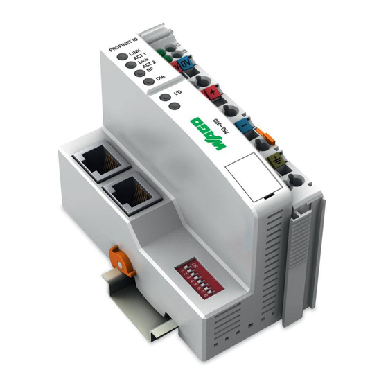
PROFINET IO Fieldbus Coupler 2-port; 100 Mbit/s; digital and analog signals
Brand:
WAGO
| Category:
I/O Systems
| Size: 7 MB
Table of Contents
Table of Contents
3
1 Notes about this Documentation
8
Validity of this Documentation
8
Copyright
8
Symbols
9
Number Notation
11
Font Conventions
11
Table 1: Number Notation
11
Table 2: Font Conventions
11
Abbreviations and Terms
12
Table 3: Abbreviations and Terms Used in this Manual
12
2 Important Notes
14
Legal Bases
14
Subject to Changes
14
Personnel Qualifications
14
Use of the WAGO-I/O-SYSTEM 750 in Compliance with Underlying Provisions
14
Technical Condition of Specified Devices
15
Safety Advice (Precautions)
16
3 System Description
18
Figure 1: Fieldbus Node (Example)
18
Manufacturing Number
19
Hardware Address (MAC ID)
19
Figure 2: Marking Area for Serial Numbers
19
Component Update
21
Storage, Assembly and Transport
21
Assembly Guidelines/Standards
22
Power Supply
23
Isolation
23
Figure 3: Isolation for Fieldbus Couplers/Controllers (Example)
23
System Supply
24
Connection
24
Figure 4: System Supply Via Fieldbus Coupler/Controller (Left) and Via Internal System Supply Module (Right)
24
Table 4: Legend for Figure "System Supply Via Fieldbus Coupler/Controller (Left) and Via Internal System Supply Module (Right)
24
Dimensioning
25
Figure 5: System Voltage for Standard Couplers/Controllers and Extended ECO
25
Table 5: Alignment
25
Field Supply
28
Connection
28
Figure 6: Field Supply for Standard Couplers/Controllers and Extended ECO
28
Table 6: Legend for Figure "Field Supply for Standard Couplers/Controllers and Extended ECO Couplers
29
Fusing
30
Figure 7: Supply Module with Fuse Carrier (Example 750-610)
30
Table 7: Power Supply Modules
30
Figure 8: Removing the Fuse Carrier
31
Figure 9: Opening the Fuse Carrier
31
Figure 10: Changing the Fuse
31
Figure 11: Fuse Modules for Automotive Fuses, Series 282
32
Figure 12: Fuse Modules for Automotive Fuses, Series 2006
32
Figure 13: Fuse Modules with Pivotable Fuse Carrier, Series 281
32
Figure 14: Fuse Modules with Pivotable Fuse Carrier, Series 2002
32
Supplementary Power Supply Regulations
33
Figure 15: Power Supply Concept
33
Table 8: Filter Modules for 24 V Supply
33
Supply Example
34
Figure 16: Supply Example for Standard Couplers/Controllers
34
Table 9: Legend for Figure "Supply Example for Fieldbus Coupler/Controller
35
Power Supply Unit
36
Table 10: WAGO Power Supply Units (Selection)
36
Grounding
37
Grounding the DIN Rail
37
Framework Assembly
37
Insulated Assembly
37
Table 11: WAGO Ground Wire Terminals
37
Grounding Function
38
Figure 17: Carrier Rail Contact (Example)
38
Shielding
39
General
39
Bus Cables
39
Figure 18: Cable Shield at Ground Potential
39
Signal Lines
40
WAGO Shield Connecting System
40
Figure 19: Examples of the WAGO Shield Connecting System
40
Figure 20: Application of the WAGO Shield Connecting System
40
4 Device Description
41
Fieldbus Coupler Properties
42
General Specifications
42
Manual Version
42
PROFINET IO Properties
42
Implemented Protocols and Services
43
Table 12: PROFINET IO Properties and Specifications
43
Supported Profiles for PROFINET IO
44
View
45
Table 13: Legend for Figure "View Fieldbus Coupler PROFINET IO
46
Connectors
47
Device Supply
47
Figure 22: Device Supply
47
Fieldbus Connection
48
Figure 23: RJ-45 Connector
48
Table 14: RJ-45 Connector and RJ-45 Connector Configuration
48
Display Elements
49
Figure 24: Display Elements
49
Table 15: Display Elements Fieldbus Status
49
Table 16: Display Elements Node Status
49
Table 17: Display Elements Supply Voltage
49
Operating Elements
51
Service Interface
51
Figure 25: Service Interface (Closed and Opened Flap)
51
Table 18: Legend for Figure "Service Interface (Closed and Opened Flap)
51
DIP Switch
52
Figure 26: DIP Switch
52
Table 19: DIP Switch - Explanation of the 8 Slide Switches
53
Table 20: Example DIP Switch Setting
53
Technical Data
55
Device Data
55
Table 21: Technical Data - Device Data
55
System Data
56
Supply
56
Accessories
56
Connection Type
56
Table 22: Technical Data - System Data
56
Table 23: Technical Data - Supply
56
Table 24: Technical Data - Accessories
56
Table 25: Technical Data - Field Wiring
56
Table 26: Technical Data - Power Jumper Contacts
56
Climatic Environmental Conditions
57
Table 27: Technical Data - Data Contacts
57
Table 28: Technical Data - Climatic Environmental Conditions
57
Approvals
58
Standards and Guidelines
59
5 Mounting
60
Installation Position
60
Overall Configuration
61
Mounting Onto Carrier Rail
62
Carrier Rail Properties
62
WAGO DIN Rail
63
Spacing
63
Figure 27: Spacing
63
Table 29: WAGO DIN Rail
63
Mounting Sequence
64
Inserting and Removing Devices
65
Inserting the Fieldbus Coupler/Controller
66
Figure 28: Release Tab Standard Fieldbus Coupler/Controller (Example)
66
Figure 29: Release Tab of Extended ECO Fieldbus Coupler (Example)
66
Removing the Fieldbus Coupler/Controller
67
Figure 30: Release Tab ECO Coupler
67
Inserting the I/O Module
68
Figure 31: Insert I/O Module (Example)
68
Figure 32: Snap the I/O Module into Place (Example)
68
Removing the I/O Module
69
Figure 33: Removing the I/O Module (Example)
69
6 Connect Devices
70
Data Contacts/Internal Bus
70
Figure 34: Data Contacts
70
Power Contacts/Field Supply
71
Figure 35: Example for the Arrangement of Power Contacts
71
Connecting a Conductor to the CAGE CLAMP
72
Figure 36: Connecting a Conductor to a CAGE CLAMP
72
7 Function Description
73
Device Start-Up and Initialization
74
Figure 37: Fieldbus Coupler Operating System
74
Switch Port Settings
75
Identification and Maintenance Data Sets (I&M)
75
Table 30: Identification and Maintenance Data Sets (I&M)
75
Process Data Architecture
76
Basic Structure
76
Allocation of the Input and Output Data
76
Figure 38: Allocation of the Input and Output Data
77
Process Data Qualifiers in Telegrams for PROFINET IO
78
One Byte Ioxs Process Data Qualifiers
78
Two Byte Ioxs Process Data Qualifiers
78
Examples of One and Two Byte Ioxs Process Data Qualifiers
78
Table 31: Example 1 for Process Data Qualifiers for 2-Channel Digital Input
78
Table 32: Example 2 for Process Data Qualifiers for 2-Channel Digital Output
79
Table 33: Example 3 for Process Data Qualifiers for 2-Channel Analog Input and
79
Table 34: Example 4 for Process Data Qualifiers for Special-Purpose Modules, SSI Sensor Interface
79
Configuration Limits
80
Minimum Configuration
80
Maximum Configuration
80
Flexible Configuration of Digital I/O Modules
81
Packaging Information from Digital Input and Output Modules
81
Rules for Packaging Digital Information
82
Example of Packaging Digital Information
83
Table 35: Example for a Station with the Following Selected Submodules
83
Possible Errors When Packaging Digital Information
84
Figure 39: Output Process Data in the Frame IOC IOD
84
Figure 40: Input Process Data in the PROFINET IO Frame IOD IOC
84
Using Fail-Safe I/O Modules (Profisafe V2)
86
Individual Parameterization of I/O Modules Via Ipar Server
87
Figure 41: Ipar Server
87
Table 36: Legend for the Figure "Ipar Server
88
Firmware Update
89
8 Commissioning
91
General Procedure
91
Procedure Description
92
Real Time Data Exchange Establishment
93
Perform Configuration Steps
93
GSD File
95
Parameterization
96
Parameterization of the Station Proxy (DAP)
96
Restart on K-Bus Failure
96
Internal Data Bus Extension
96
Table 37: Parameterization - Overview of Attributes for the Station Proxy (DAP)
96
Table 38: Parameterization DAP - Attribute Restart on K-Bus Failure
96
Table 39: Parameterization DAP - Attribute Internal Data Bus Extension
96
Diagnostics of External Module/Channel Errors
97
Process Data Representation
97
Response to PROFINET IO Failure
97
Table 40: Parameterization DAP - Attribute Diagnostics of External Module/Channel Errors
97
Table 41: Parameterization DAP - Process Data Representation
97
Table 42: Parameterization DAP - Attribute Response to PROFINET IO Failure
97
Response to K-Bus Failure
98
Parameterization of the I/O-Modules
98
Table 43: Parameterization DAP - Attribute Response to K-Bus Failure
98
Standard Modul Parameters
99
Table 44: Default Module Parameters
99
Fail-Safe Module Parameters (F-Parameter)
100
General Channel Parameters
100
Table 45: Fail-Safe Module Parameters (F-Parameters)
100
Specific Channel Parameters
101
Table 46: General Channel Parameters
101
Demand Data Exchange (Acyclic Communication)
102
9 Configuring Via the Web-Based Management System (WBM)
103
Information
105
Figure 42: WBM Page „Information
105
Table 47: WBM Page "Information
106
Snmp
107
SNMP V1/V2C
108
Figure 43: WBM Page "SNMP
108
Table 48: WBM Page "SNMP
108
Snmp V3
110
Figure 44: WBM Page "SNMP V3
110
Table 49: WBM Page "SNMP V3
111
Clock
112
Figure 45: WBM Page "Clock
112
Table 50: WBM Page "Clock
112
Security
113
Figure 46: WBM Page "Security
114
Table 51: WBM Page "Security
114
10 Diagnostics
116
LED Signaling
116
Figure 47: Display Elements
116
Table 52: LED Assignment for Diagnostics
116
Evaluating the Fieldbus Status
117
Table 53: Fieldbus Diagnostics - Solution in Case of Error
117
Evaluating the Node Status
118
Table 54: Node Status Diagnostics - Solution in Event of Error
118
Figure 48: Node Status - I/O LED Signaling
119
Figure 49: Error Message Coding
119
Table 55: Blink Code Table for the 'I/O' LED Signaling, Error Code 1
120
Table 56: Blink Code Table for the I/O LED Signaling, Error Code 2
121
Table 57: Blink Code Table for the I/O LED Signaling, Error Code 3
122
Table 58: Blink Code Table for the I/O LED Signaling, Error Code 4
123
Table 59: Blink Code Table for the I/O LED Signaling, Error Code 5
123
Evaluating Power Supply Status
124
Table 60: Blink Code Table for the 'I/O' LED Signaling, Error Code 6
124
Table 61: Blink Code Table for the 'I/O' LED Signaling, Error Code 7
124
Table 62: Power Supply Status Diagnostics - Solution in Event of Error
124
Error Response
125
Fieldbus Failure
125
Table 63: Diagnosis of Fieldbus Failure
125
Internal Data Bus Failure
126
PROFINET IO Diagnostics
127
Diagnosis Data Sets
127
WAGO-I/O-System
127
Table 64: Retrievable Record Data Sets for Diagnostics
127
Structure of the Standardized Diagnosis Data Sets
128
Table 65: Structure Head for the Diagnostic Data
128
11 Fieldbus Communication
129
Standard ETHERNET Protocols
129
IP, TCP and HTTP
129
Dcp
129
Lldp
130
Snmp
130
Profinet Io
131
General
131
Cabling
132
PROFINET IO Device Classes
132
Addressing
133
Figure 50: PROFINET Principle
133
PROFINET Communication Principle
134
Data Traffic
134
Communication Connection
134
Application and Communication Relationship (AR, CR)
135
System Start-Up
135
Data Exchange
136
Using Configuration Software
136
Hardware Configuration in the Configuration Software
136
Parameterization in the Configuration Software
136
Communication Configuration in the Configuration Software
136
12 O Modules
137
13 Use in Hazardous Environments
138
Marking Configuration Examples
139
Marking for Europe According to ATEX and IEC-Ex
139
Figure 51: Side Marking Example for Approved I/O Modules According to ATEX and Iecex
139
Figure 52: Text Detail - Marking Example for Approved I/O Modules According to ATEX and Iecex
139
Table 66: Description of Marking Example for Approved I/O Modules According to ATEX and Iecex
140
Table 68: Description of Marking Example for Approved I/O Modules According
140
Figure 53: Side Marking Example for Approved Ex I I/O Modules According to ATEX and Iecex
141
Figure 54: Text Detail - Marking Example for Approved Ex I I/O Modules According to ATEX and Iecex
141
Table 67: Description of Marking Example for Approved Ex I I/O Modules According to ATEX and Iecex
143
Marking for America According to NEC 500
144
Figure 55: Side Marking Example for I/O Modules According to NEC 500
144
Figure 56: Text Detail - Marking Example for Approved I/O Modules According
144
Installation Regulations
145
Special Conditions for Safe Use (ATEX Certificate TÜV 07 ATEX 554086 X)
146
Special Conditions for Safe Use (ATEX Certificate TÜV 12 ATEX 106032 X)
147
Special Conditions for Safe Use (IEC-Ex Certificate TUN 09.0001 X)
148
Special Conditions for Safe Use (IEC-Ex Certificate Iecex TUN 12.0039 X)
149
Special Conditions for Safe Use According to ANSI/ISA 12.12.01
150
14 Appendix
151
Module and Submodule Types of the I/O-Modules
151
Digital Input Modules
151
Table 69: Module Types - Digital Input Modules
151
Table 70: Submodule Types and Data Lengths - Digital Input Modules
152
Digital Output Modules
155
Table 71: Module Types - Digital Output Modules
155
Table 72: Submodule Types and Data Lenghts - Digital Output Modules
156
Digital Input/Output Modules
159
Table 73: Module Types - Digital Input/Output Modules
159
Analog Input Modules
160
Table 75: Module Types - Analog Input Modules
160
Table 76: Submodule Types and Data Lengths - Analog Input Modules
161
Analog Output Modules
162
Table 77: Module Types - Analog Output Modules
162
Table 78: Submodule Types and Data Lengths - Analog Output Modules
162
Specialty Modules
163
Up/Down Counter
163
Table 79: Module Types - Up/Down Counter
163
Table 80: Submodule Types and Data Lengths - Up/Down Counter
163
2-Channel Pulse Width Modules
164
Table 81: Module Types - 2-Channel Pulse Width Output Modules
164
Table 82: Submodule Types and Data Lengths - 2-Channel Pulse Width Output
164
Distance and Angle Measurement Modules
165
Table 83: Module Types - Distance and Angle Measurement Modules
165
Table 84: Submodule Types and Data Lengths - Distance and Angle
165
Serial Interfaces
166
Table 85: Module Types - Serial Interfaces
166
Table 86: Submodule Types and Data Lengths - Serial Interfaces
166
DC-Drive Controller
167
RTC Module
167
Table 87: Module Types - DC-Drive Controller
167
Table 88: Submodule Types and Data Lengths - DC-Drive Controller
167
Table 89: Module Types - RTC Module
167
Table 90: Submodule Types and Data Lengths - RTC Module
167
DALI/DSI Master and DALI Multi-Master Modules
168
Table 91: Module Types - DALI/DSI Master and DALI Multi-Master Modules
168
Table 92: Submodule Types and Data Lengths - DALI/DSI Master and DALI
168
AS-Interface Master Modules
169
Table 93: Module Types - AS-Interface Master Modules
169
Radio Receiver Modules
170
Table 95: Module Types - Radio Receiver Modules
170
Table 96: Submodule Types and Data Lengths - Radio Receiver Modules
170
14.1.6.10 MP-Bus Master Modules
171
14.1.6.11 Vibration Monitoring
171
Table 97: Module Types - MP-Bus Master Modules
171
Table 98: Submodule Types and Data Lengths - MP-Bus Master Modules
171
Table 99: Module Types - Vibration Monitoring
171
Table 100: Submodule Types and Data Lengths - Vibration Monitoring
171
14.1.6.12 Safety Modules Profisafe V2
172
Table 101: Module Types - Safety Modules Profisafe V2
172
Table 102: Submodule Types and Data Lengths - Safety Modules Profisafe V2 Ipar
172
14.1.6.13 Stepper Modules
173
Table 103: Module Types - Stepper Modules
173
Table 104: Submodule Types and Data Lengths - Stepper Modules
173
System Modules
174
Power Supply Modules
174
Table 105: Module Types - Power Supply Modules
174
Table 106: Submodule Types and Data Lengths- Power Supply Modules
174
Parameters of the I/O Modules
175
Digital Input Modules (DI, DI DIA)
175
Table 107: Parameterization - Overview of Attributes for Digital Input Modules
175
Table 108: Parameterization DI, DIA - "Diagnostics" Attribute
175
Digital Output Modules (DO)
176
Table 109: Parameterization - Overview of the Attributes for Digital Output
176
Table 110: Parameterization DO - "Substitute Value Behavior of the Outputs
176
Table 111: Parameterization DO - "Substitute Output Status" Attribute
176
Digital Output Modules with Diagnostics (DO, DIA)
177
Table 112: Parameterization - Overview of the Additional Attributes for Digital Output Modules with Diagnostics (DO, DIA)
177
Table 113: Parameterization DO, DIA - "Diagnostics" Attribute
177
Analog Input Modules
178
Table 114: Parameterization - Overview of the Attributes for Analog Input
178
Table 115: Parameterization AI - "Diagnostics" Attribute
178
Special AI Module Types (AI, RTD, TC, PM)
179
Table 117: Parameterization - Overview of Additional Attributes for Special AI Module Types (2/4 AI, RTD, TC, PM)
179
Table 118: Parameterization 2AI, RTD 463 - "Sensor Type" Attribute
179
Table 119: Parameterization 4AI, RTD 464 - "Sensor Type" Attribute
180
Table 120: Parameterization 4AI, RTD 464/020-000 - "Sensor Type" Attribute
180
Table 121: Parameterization 2AI, RTD 464 - "Connection Type" Attribute
180
Table 122: Parameterization 4AI, RTD 450 - "Sensor Type" Attribute
181
Table 123: Parameterization 2AI, RTD 450 - "Connection Type" Attribute
181
Table 124: Parameterization 8AI, RTD 451 - "Sensor Type" Attribute
182
Table 125: Parameterization 8AI, RTD 451 - "Connection Type" Attribute
182
Table 126: Parameterization AI, PM 494 - "DC Measurement" Attribute
182
Table 127: Parameterization AI, 3 PM - "Internal Data Bus Monitoring" Attribute
182
Table 128: Parameterization AI, 3 PM - "Line Frequency" Attribute
182
Table 129: Parameterization AI, 3 PM 495 - "Rogowski Coil Detection" Attribute
183
Table 130: Parameterization AI, 3 PM - "Phase for Peak Value" Attribute
183
Table 131: Parameterization AI, 3 PM - "Autoreset Min./Max. Values" Attribute
183
Table 132: Parameterization AI, 3 PM - "User Scaling" Attribute
183
Table 133: Parameterization AI, 3 PM - "Scaling Factor for Energy Values
183
Table 134: Parameterization AI, 3 PM - "Scaling Factor for Energy Values
183
Table 135: Parameterization AI, 3 PM - "Storage Interval for Energy Consumption [S]" Attribute
184
Table 136: Parameterization AI, 3 PM - "Transformer Ratio" Attribute
184
Table 137: Parameterization AI, 3 PM - "Operating Interval for Peak Value [HW]" Attribute
184
Table 138: Parameterization AI, 3 PM - "Reset Interval Min./Max. [200 Ms]" Attribute
184
Analog Output Modules (AO)
185
Table 139: Parameterization - Overview of the Attributes for Analog Output
185
Table 140: Parameterization AO - "Substitute Value Behavior" Attribute
185
Table 141: Parameterization AO - "Substitute Output Data" Attribute
185
Table 142: Parameterization AO, DIA - "Process Data Format" Attribute
185
Analog Output Modules with Diagnostics (AO, DIA)
186
Table 143: Parameterization - Overview of the Attributes for Additional Analog Output Modules with Diagnostics (AO, DIA)
186
Table 144: Parameterization AO, DIA - "Diagnostics" Attribute
186
Special AO Module Types with Parameter Channel (AO, 562, 563)
187
Table 145: Parameterization - Overview of Additional Attributes for Special AO Module Types (AO, 562, 563)
187
Table 146: Parameterization AO, 562, 563 - "User Scaling" Attribute
187
Table 147: Parameterization AO, 562, 563 - "Calibration" Attribute
187
Table 148: Parameterization AO, 562, 563 - "Number Notation" Attribute
187
Table 149: Parameterization AO, 562, 563 - "Operating Mode" Attribute
188
Table 150: Parameterization AO, 562, 563 - "Limiting Value Overrange
188
Table 151: Parameterization AO, 562, 563 - "Output" Attribute
188
Table 152: Parameterization AO, 562, 563 - "Behavior on Internal Data Bus
188
Table 153: Parameterization AO, 562, 563 - "Switch-On Delay [S]" Attribute
188
Spezial Modules
189
Table 154: Parameterization SF, DIA - "Diagnostics" Attribute
189
Table 155: Parameterization SF, Asi 655, BT 644 - "Mailbox Length" Attribute
189
Table 156: Parameterization SF, Asi 655, BT 644 - "Cross Fade Mailbox
189
14.2.10 System Modules
190
Table 158: Parameterization - Overview of the Attributes for the System Modules with Diagnostics Capabilities (AO)
190
Table 159: Parameterization PS, DIA - "Diagnostics" "Transmitter or Load
190
Record Data Sets
191
Table 160: Record Data Sets
191
Detailed Structures I&M 0
193
Table 161: Data Set I&M 0
193
Structure of the Standardized Diagnosis Data Sets
194
Table 162: "Blocktype
194
Table 163: "Version
194
Table 164: "Head of the Structure
194
Channel Specific Diagnostics
195
Channel Diagnostics
195
Table 165: General Structure "Channeldiagnosis" and „Extchanneldiagnosis
195
Table 166: "Channeldiagnosisdata" Instance Structure
195
Fault Cases of I/O Modules with Diagnostics Capability
198
14.5.1.2.1 Digital Input Modules
198
Table 167: Fault Cases of Digital Input Modules with Diagnostics Capability
198
14.5.1.2.2 Digital Output Modules
199
Table 168: Fault Cases of Digital Output Modules with Diagnostics Capability
199
14.5.1.2.3 Analog Input Modules
200
Table 169: Fault Cases of Analog Output Modules with Diagnostics Capability
200
14.5.1.2.4 Analog Output Modules
201
Table 170: Fault Cases of Analog Output Modules with Diagnostics Capability
201
14.5.1.2.5 Complex I/O Modules
202
Table 171: Fault Cases of Complex I/O Modules with Diagnostics Capability
202
14.5.1.2.6 Profisafe V2 Ipar I/O Modules
203
Extended Channel Diagnostics
204
Table 172: "Extchanneldiagnosisdata" Instance Structure
204
Table 173: Additional Error Information Error Type "Configuration Fault
205
Table 174: Additional Error Information Fault Type "Missing Parameters 0X001F
207
Table 175: Additional Error Information Fault Type "Internal Bus Fault 0X100
208
Table 176: Additional Error Information Fault Type "Configuration Fault
208
Table 177: Additional Error Information Fault Type "Reconfiguration Required
209
Difference between Real and Expected Configuration
210
Table 178: Initial Structure "Modulediffblock
210
Table 179: Structure of the Odd Modules Within the Configuration
211
Table 180: Structure of the Erroneously Configured Submodules
212
List of Figures
215
List of Tables
217
Advertisement
WAGO 750-370 Manual (264 pages)
Modular I/O-System Fieldbus Coupler PROFINET IO
Brand:
WAGO
| Category:
I/O Systems
| Size: 4 MB
Table of Contents
Table of Contents
3
1 Important Notes
9
Legal Bases
9
Copyright
9
Personnel Qualifications
9
Use of the 750 Series in Compliance with Underlying Provisions
10
Technical Condition of Specified Devices
10
Standards and Guidelines for Operating the 750 Series
11
Symbols
12
Safety Information
13
Font Conventions
14
Number Notation
14
Scope
14
Abbreviation
15
2 The WAGO-I/O-SYSTEM 750
16
System Description
16
Technical Data
17
Manufacturing Number
23
Component Update
24
Storage, Assembly and Transport
24
Mechanical Setup
25
Installation Position
25
Total Expansion
25
Assembly Onto Carrier Rail
26
Carrier Rail Properties
26
WAGO DIN Rail
27
Spacing
27
Plugging and Removal of the Components
28
Assembly Sequence
29
Internal Bus/Data Contacts
30
Power Contacts
31
Wire Connection
32
Power Supply
33
Isolation
33
System Supply
34
Connection
34
Alignment
35
Field Supply
37
Connection
37
Fusing
38
Supplementary Power Supply Regulations
41
Supply Example
42
Power Supply Unit
43
Grounding
44
Grounding the DIN Rail
44
Framework Assembly
44
Insulated Assembly
44
Grounding Function
45
Grounding Protection
46
Shielding (Screening)
47
General
47
Bus Conductors
47
Signal Conductors
47
WAGO Shield (Screen) Connecting System
48
Assembly Guidelines/Standards
48
3 Fieldbus Coupler
49
Description
49
Profinet Io 750-370
50
Hardware
50
View
50
Power Supply
51
Fieldbus Connection
52
Display Elements
53
Configuration Interface
54
I/O Device Configuration
55
GSD File
55
Configuration
56
Configuring Digital I/O Modules
56
Configuring Analog I/O Modules
61
Configuring Specialty Modules
63
Parameter Setting
65
Station Parameters
65
Standard Module Parameters
67
Fault Safe Module Parameters (F-Parameters)
68
Channel Parameters
69
Station Naming
70
Device Name Assignment Via Configuration Tool
70
Device Name Assignment Via DIP Switch Settings
70
Initialization Phase of the Fieldbus Coupler
71
Process Image
72
Local Process Image
72
Allocation of the Input and Output Data
73
Digital Input Modules
74
Digital Output Modules
75
Analog Input Modules
78
Analog Output Modules
79
Specialty Modules
80
Meter and Position Transmitter Interfaces
80
Pulse Width Output Module
82
Serial Interfaces and Gateways
83
Profisafe I/O Modules
84
System Modules
84
Potential Supply Modules
84
Example
85
Wago-I/O-System
86
Establishing the Connection
87
Configuration and Parameter Setting of I/O Modules
87
Diagnostics
88
Diagnostics Data Sets
88
Structure of the Standardized Diagnosis Data Sets
88
Channel Specific Diagnostics
89
Channel Diagnostics
90
Fault Types of I/O Modules with Diagnostics Capability
92
Fault Cases of I/O Modules with Diagnostics Capability
94
Extended Channel Diagnostics
97
Difference between Target and Actual Configuration
103
Data Set for Identification and Servicing Purposes (I&M 0)
105
Acyclic Communication Using Record Data Sets
106
Data Set Detail Diagnostics for Profisafe I/O Modules
106
Information about the Web-Based Management System (WBM)
108
SNMP Configuration
113
Settings Via WBM
113
MIB II Description
115
Standard Traps
116
LED Indication
117
Blink Code
117
Fieldbus Status
118
Node Status - 'I/O' LED Blinking Code
119
I/O' LED Error Messages
121
Status Supply Voltage
126
Error Response
127
Fieldbus Failure
127
Internal Bus Failure
127
Technical Data
128
4 Fieldbus Communication
129
Ethernet
129
General
129
Network Architecture - Principles and Regulations
131
Transmission Media
132
Network Topologies
134
Coupler Modules
137
Transmission Mode
138
Static Configuration of the Transmission Mode
138
Dynamic Configuration of the Transmission Mode
138
Errors Occurring When Configuring the Transmission Mode
139
Important Terms
139
Network Communication
142
Protocol Layer Model
142
Communication Protocols
144
Ethernet
145
Channel Access Method
146
IP-Protocol
146
Raw Ip
150
IP Multicast
151
TCP Protocol
151
Udp
152
Arp
152
Wago-I/O-System
152
Administration and Diagnosis Protocols
153
Bootp (Bootstrap Protocol)
153
HTTP (Hyper Text Transfer Protocol)
155
DHCP (Dynamic Host Configuration Protocol)
155
DNS (Domain Name Systems)
156
SNTP-Client (Simple Network Time Protocol)
156
FTP-Server (File Transfer Protocol)
157
SMTP (Simple Mail Transfer Protocol)
158
Application Protocols
159
Profinet
160
Description
160
Cabling
161
5 O Modules
162
Overview
162
Digital Input Modules
162
Digital Output Modules
164
Analog Input Modules
165
Analog Output Modules
167
Special Modules
168
System Modules
170
Structure of the PROFINET IO Process Data
171
Digital Input Modules
171
DI Modules
171
DI Modules with Diagnostics
171
DI Modules
172
Digital Output Modules
173
DO Modules
173
DO Modules with Diagnostics
173
DO Modules
174
DO Modules with Diagnostics
174
DO Modules
175
Analog Input Modules
176
AI Modules
176
AI Modules
177
AI Modules
178
Analog Output Modules
179
AO Modules
179
AO Modules
180
Specialty Modules
181
Counter Modules
181
PWM Modules
182
Wago-I/O-System
183
SSI Transmitter Interface
184
Incremental Encoder Interface
185
Serial Interfaces
186
Data Exchange Module
187
DALI/DSI Master
188
Safety I/O Modules Profisafe
189
Configuration and Parameter Setting of the Modules
190
Channel Digital Input Modules with 1 Bit Diagnostics Status Per Channel
191
Channel Digital Input Modules
193
Channel Digital Input Modules
194
Channel Digital Input Modules
195
Digital Output Modules
196
Channel Digital Output Modules with 1 Bit Diagnostics Status Per Channel
198
Channel Digital Output Modules with 2 Bit Diagnostics Status Per Channel
201
Channel Digital Output Modules
204
Channel Digital Output Modules with 1 Bit Diagnostics Status Per Channel
206
Channel Digital Output Modules
209
Channel Digital Output Modules with 1 Bit Diagnostics Status Per Channel
211
Channel Digital Output Modules
214
Channel Digital Input Modules with 1 Bit Diagnostics Status and Confirmation Per Channel
216
Analog Input Modules
220
Channel Analog Input Modules
222
Analog Output Modules
225
Channel Analog Output Modules
227
Specialty Modules
230
PWM Module
232
SSI Transmitter Interface
234
Incremental Encoder Interface
236
Digital Impulse Interface
237
Serial Interfaces and Data Exchange Module
238
Data Exchange Module
239
ENOCEAN Receiver Module
241
Wago-I/O-System
242
Profisafe Safety Modules
243
System Modules
245
6 Use in Hazardous Environments
247
For America According to NEC 500
248
Installation Regulations
249
Ansi/Isa 12.12.01
250
TÜV Nord Ex-I Applications
251
ATEX and IEC Ex
252
7 Appendix
253
IP Group
255
Iproute Table
256
ICMP Group
257
TCP Group
258
UDP Group
259
8 List of Literature
261
9 Index
262
Wago-I/O-System
263
Hansastraße
264
Advertisement
Related Products
WAGO 750-377
WAGO 750-342
WAGO 750-344
WAGO 750-345
WAGO 750-346
WAGO 750-341
WAGO 750-337
WAGO 750-338
WAGO 750-312
WAGO LONWORKS 750-319
WAGO Categories
I/O Systems
Control Unit
Power Supply
Switch
Controller
More WAGO Manuals
Login
Sign In
OR
Sign in with Facebook
Sign in with Google
Upload manual
Upload from disk
Upload from URL