Sign In
Upload
Manuals
Brands
Mitsubishi Electric Manuals
Amplifier
Melservo MR-J5 G Series
Mitsubishi Electric Melservo MR-J5 G Series Manuals
Manuals and User Guides for Mitsubishi Electric Melservo MR-J5 G Series. We have
5
Mitsubishi Electric Melservo MR-J5 G Series manuals available for free PDF download: User Manual
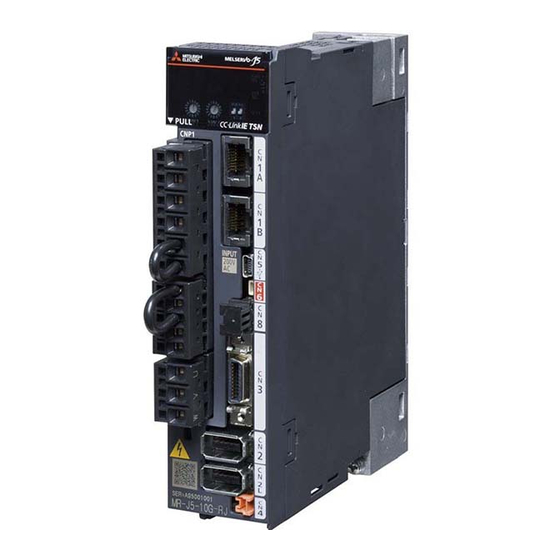
Mitsubishi Electric Melservo MR-J5 G Series User Manual (624 pages)
AC Servo System
Brand:
Mitsubishi Electric
| Category:
Controller
| Size: 16.22 MB
Table of Contents
Safety Instructions
3
About the Manual
5
Cables Used for Wiring
6
Customary Units
6
Table of Contents
7
Chapter 1 Introduction
15
Wiring Procedure
15
Servo Amplifier/Motor Combinations
16
Rotary Servo Motor
16
Geared Servo Motor
21
Linear Servo Motor
23
Direct Drive Motor
28
Wiring Check
30
Power Supply System Wiring
30
I/O Signal Wiring
32
Surrounding Environment
33
Chapter 2 Installation
34
Mounting Direction and Clearances
35
Keeping out Foreign Materials
38
Cable Stress
38
SSCNET III Cable Laying [B]
39
Fan Unit Replacement Procedure
41
List of Applicable Fan Units
41
Fan Unit Removal Procedure
42
Fan Unit Installation Procedure
43
Restrictions When Using this Product at an Altitude Exceeding 1000 M and up to 2000 M
44
Chapter 3 Signals and Wiring
45
Example Power Circuit Connections
46
200 V Class
46
400 V Class
50
Using Servo Amplifier with DC Power Supply Input
53
Example I/O Signal Connections
55
MR-J5-_G_ (Excluding MR-J5-_G_-HS_)
55
Mr-J5-_G_-Hs
58
Mr-J5W_-_G
61
Mr-J5-_B
64
Mr-J5W_-_B
67
Mr-J5-_A
70
Explanation of Power Supply System
78
Explanation of Signals
78
Power-On Procedure [G] [B]
80
Power-On Procedure [A]
81
Wiring CNP1, CNP2, and CNP3
82
Connectors and Pin Assignments
89
Precautions
89
Connectors and Pin Assignments [G]
90
Connectors and Pin Assignments [B]
95
Connectors and Pin Assignments [A]
97
Signal (Device) Explanation
100
Input Device
100
Output Device
110
Input Signal
117
Output Signal
119
Power Supply
121
Interface
122
Internal Connection Diagram [G]
122
Internal Connection Diagram [B]
128
Internal Connection Diagram [A]
132
Detailed Explanation of Interfaces
135
Source I/O Interface
139
Servo Motor with an Electromagnetic Brake
141
Connection Diagram
141
SSCNET III Cable Connection [B]
143
Grounding
145
Chapter 4 Dimensions
146
Mr-J5-_G
146
200 V Class
146
400 V Class
149
Mr-J5W_-_G
152
Mr-J5-_B
154
200 V Class
154
400 V Class
157
Mr-J5W_-_B
159
Mr-J5-_A
161
200 V Class
161
400 V Class
164
Connector
166
Mr-J5_-_G
166
Mr-J5_-_B
170
Mr-J5-_A
171
Chapter 5 Characteristics
172
Overload Protection Characteristics
172
Power Supply Capacity and Generated Loss
175
Power Supply Capacity
175
Generated Loss
186
Using Servo Amplifier with DC Power Supply Input
188
Dynamic Brake Characteristics
189
Dynamic Brake Operation
190
Cable Flex Life
253
Inrush Currents at Power-On of Main Circuit and Control Circuit
254
Chapter 6 Options and Peripheral Equipment
255
Cables/Connector Sets
255
Combinations of Cables/Connector Sets
256
MR-D05UDL3M-B STO Cable
266
MR-AHSCN7CBL2M10M Output Cable for Analog Monitor and A/B/Z-Phase Pulse [G]
267
Ethernet Cable [G]
268
SSCNET III Cable [B]
269
Regenerative Option
271
Combination and Regenerative Power
271
Selection of the Regenerative Option (1-Axis Servo Amplifier)
273
Selection of the Regenerative Option (Multi-Axis Servo Amplifier)
276
Servo Parameter Setting
280
Connection of Regenerative Option
280
Mounting Direction
281
Dimensions
282
MR-CM Simple Converter
287
Combination of Simple Converter and Servo Amplifier
287
Servo Amplifier Setting When Using a Simple Converter
287
Simple Converter Standard Specifications
287
External Interface
289
Signals and Wiring
292
Dimensions
294
Peripheral Equipment
295
Mounting Direction and Clearances
296
Multifunction Regeneration Converter (FR-XC-(H))
297
Precautions
297
Servo Amplifier Settings
297
Capacity Selection
297
Connection Diagram
300
Wiring and Peripheral Options
302
PS7DW-20V14B-F Junction Terminal Block (Recommended) (1-Axis Servo Amplifier) [G] [B]
306
MR-TB26A Junction Terminal Block (Multi-Axis Servo Amplifier) [G] [B]
308
MR-TB50 Junction Terminal Block [A]
310
MR Configurator2
312
Engineering Tool
312
Precautions for Using USB Communication Function and Ethernet Communication Function
312
Battery
313
Selection of Battery
313
MR-BAT6V1SET Battery
314
MR-BAT6V1SET-A Battery
317
MR-BT6VCASE Battery Case
320
MR-BAT6V1 Battery
326
Battery Cable and Junction Battery Cable
327
Selection Example of Wires
328
Molded-Case Circuit Breakers, Fuses, Magnetic Contactors
331
Selection Example
331
Main Circuit Wiring (Connecting Multiple Servo Amplifiers to One Molded-Case Circuit Breaker)
337
Example Settings that Comply with IEC/EN/UL 61800-5-1 and CSA C22.2 No.274
340
Power Factor Improving DC Reactor
343
Power Factor Improving AC Reactor
350
Relay (Recommended)
355
Noise Reduction Techniques
356
Noise Reduction Products
360
Earth-Leakage Current Breaker
364
Selection Method
364
Selection Example
367
EMC Filter (Recommended)
369
MR-J3-D05 Safety Logic Unit
375
Contents of the Package
375
Terms Related to Safety
375
Precautions
376
Residual Risks
376
Block Diagram and Timing Chart
377
Maintenance and Disposal
377
Functions and Configuration
378
Signal
381
LED Display
388
Rotary Switch Settings
389
Troubleshooting
389
Dimensions
390
Installation
391
Combinations of Cables and Connectors
392
J5-CHP07-10P Cabinet-Mounting Attachment
393
Compatible Models
393
Dimensions
393
View When Installed
393
Fitting Method
394
Components
395
Installation Dimensions
395
J5-CHP08 Grounding Terminal Attachment
400
Compatible Models
400
Restrictions
400
Appearance and Dimensions
400
View When Installed
401
Components
402
Installation Dimensions
402
MR-ASCHP06 Shield Clamp Attachment
407
Compatible Models
407
Appearance and Dimensions
407
Cable Connection Method
408
View When Installed
409
Components
410
Installation Dimensions
410
Cables Manufactured by Mitsubishi Electric System & Service Co., Ltd
411
SSCNET III Cable [B]
411
SCC 15-F Shield Connection Clamp
412
Compatible Models
412
Applicable Wire Diameter
412
Cable Connection Method
412
View When Installed
413
Chapter 7 Absolute Position Detection System
414
Outline
414
Characteristics
414
Restrictions [G]
414
Restrictions [B]
414
Restrictions [A]
414
Precautions [G] [A]
415
Precautions [B]
415
Configuration
416
Servo Parameter Setting [G]
416
Servo Parameter Setting [B]
416
Servo Parameter Setting [A]
416
Homing [G] [A]
417
Homing [B]
417
Checking the Detected Absolute Position Data
417
Procedure of Replacing a Servo Motor with Battery-Less Absolute Position Encoder
419
Procedure of Replacing a Servo Amplifier Without Losing the Absolute Position Data [B]
420
Configuration and Specifications
421
Connecting the Battery-Less Encoder
421
Connecting the Battery Backup Type Absolute Position Encoder
423
Absolute Position Detection System by DIO [A]
427
Standard Connection Example
427
Signal Explanation
428
Startup Procedure
429
Absolute Position Data Transfer Protocol
430
Absolute Position Data Transfer Errors
443
Absolute Position Detection System Via Communication [A]
445
Serial Communication Command
445
Absolute Position Data Transfer Protocol
446
Chapter 8 Using Sto Function
449
Introduction
449
Outline
449
Terms Related to Safety
449
Precautions
449
Residual Risks of the STO Function
450
Specifications
450
Maintenance
451
Functional Safety I/O Signal Connector (CN8) and Pin Assignments
452
Pin Assignment
452
Signal (Device) Explanation
452
How to Pull out the STO Cable
453
Connection Example
454
Precautions for Compliance with Stop Category 1 (IEC/EN 60204-1)
454
Precautions for Compliance with Stop Category 0 (IEC/EN 60204-1)
454
Connection Example for CN8 Connector
455
External I/O Signal Connection Example Using the MR-J3-D05 Safety Logic Unit
455
External I/O Signal Connection Example Using an External Safety Relay Unit
458
Detailed Explanation of Interfaces
460
Sink I/O Interface
460
Source I/O Interface
462
Chapter 9 Using Functional Safety [G] (Exculuding Mr-J5-_G_-Hs_)
463
Introduction
463
Function Block Diagram
464
Safety Sub-Function Control by Input Device
464
Safety Sub-Function Control by Network
465
System Configuration
466
Safety Sub-Function Control by Input Device
466
Safety Sub-Function Control by Network
467
Specifications
468
Connectors and Pin Assignments
468
Example I/O Signal Connections
469
Input Signal
469
Output Signal
470
Connecting I/O Interfaces
471
Source Input
471
Sink Input
471
Wiring the SBC Output
472
Noise Reduction Techniques
473
Advertisement
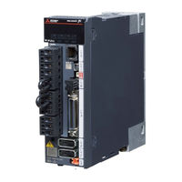
Mitsubishi Electric Melservo MR-J5 G Series User Manual (442 pages)
AC Servo System
Brand:
Mitsubishi Electric
| Category:
Controller
| Size: 43.32 MB
Table of Contents
Safety Instructions
3
About the Manual
5
Object Units
6
U.s. Customary Units
6
Table of Contents
7
Chapter 1 Function
13
Function Explanation
13
Chapter 2 Control Mode
21
Control Mode [G] [WG]
21
Control Switching
21
Cyclic Synchronous Position Mode (Csp)
22
Cyclic Synchronous Velocity Mode (Csv)
24
Cyclic Synchronous Torque Mode (Cst)
26
Profile Position Mode (Pp)
28
Profile Velocity Mode (Pv)
32
Profile Torque Mode (Tq)
36
Continuous Operation to Torque Control Mode (Ct)
39
Homing Mode (Hm) and Homing
44
Control Mode [A]
71
Control Switching
71
Position Control Mode (P)
71
Speed Control Mode (S)
75
Torque Control Mode (T)
77
Position/Speed Control Switching Mode (P/S)
80
Speed/Torque Control Switching Mode (S/T)
82
Torque/Position Control Switch Mode (T/P)
84
Chapter 3 Basic Function
85
Outline of Servo Parameter and Object Dictionary
85
Servo Parameter
85
Object Dictionary [G] [WG]
87
Rotation/Travel Direction Selection [G] [WG]
88
Setting Methods of Functions
89
Rotation/Travel Direction Selection [A]
92
Setting Methods of Functions
93
Stroke Limit Function [G] [WG]
94
Explanation of the Stroke Limit Signal Names
94
Setting Methods of Functions
95
Stop Method at Stroke Limit Detection
98
Servo Parameter List
99
Stroke Limit Function [A]
100
Setting Methods of Functions
100
Stop Method at Stroke Limit Detection
101
Servo Parameter List
101
Limit Switch Release Position Assessment Function [G] [WG]
102
Outline
102
Precautions
102
Setting Methods of Functions
102
Command Unit Select Function [G] [WG]
103
Position Command Unit Selection Function
103
Speed Command Unit Selection Function
105
Command Unit Select Function [A]
106
Torque Command Unit Selection Function
106
Electronic Gear Function [G] [WG]
107
Setting Method
107
Setting Example
108
Electronic Gear Function [A]
113
Setting Method
113
Setting Example
114
Electronic Gear Selection Function
116
In-Position Range Setting
117
Setting Method [G] [WG]
118
Setting Method [A]
118
Assigning I/O Devices
119
Setting Method [G] [WG]
120
Setting Method [A]
121
Regenerative Option Selection
122
Regenerative Option
122
Alarm Function
123
Operation Status at Alarm Occurrence [G] [WG]
123
Operation Status at Alarm Occurrence [A]
123
Operation Status at Warning Occurrence [G] [WG]
124
Operation Status at Warning Occurrence [A]
124
Returning from an Alarm [G] [WG]
125
Returning from an Alarm [A]
125
Returning from a Warning
125
Alarm History [G] [WG]
125
Alarm History [A]
127
Stop Method at Occurrence of Alarms/Warnings
127
Timing Chart at Alarm Occurrence
128
Forced Stop Deceleration Function
130
Setting Method [G] [WG]
130
Setting Method [A]
131
Timing Chart [G] [WG]
131
Timing Chart [A]
132
Electromagnetic Brake Interlock Function
133
Base Circuit Shut-Off Delay Time Function
133
Setting Method [G] [WG]
133
Setting Method [A]
134
Timing Chart
135
Vertical Axis Freefall Prevention Function
143
Setting Method [G] [WG]
143
Setting Method [A]
143
Timing Chart [G] [WG]
144
Timing Chart [A]
144
Acceleration/Deceleration Function
145
Acceleration/Deceleration Time Constant
145
S-Pattern Acceleration/Deceleration Time Constant [G] [WG]
147
S-Pattern Acceleration/Deceleration Time Constant [A]
148
Acceleration/Deceleration [G] [WG]
149
Quick Stop [G] [WG]
151
Objects for Setting
151
Timing Chart
152
Halt [G] [WG]
153
Objects for Setting
153
Timing Chart
153
Command Pulse Train Monitoring Function [A]
154
Setting a Command Frequency Error Threshold
154
Setting PEN (Command Input Permission Signal)
154
Chapter 4 Applicable Functions
155
Tough Drive Function
157
Vibration Tough Drive
157
Instantaneous Power Failure Tough Drive
157
Compliance with SEMI-F47 Standard
161
Setting Method
161
Behavior
161
Requirements of the SEMI-F47 Standard
162
Calculation Method of Tolerance against Instantaneous Power Failure
162
Scale Measurement Function [G] [WG]
163
Outline
163
Function Block Diagram
164
System Configuration
165
Scale Measurement Encoders
167
Setting Method
170
Related Objects
173
Touch Probe [G] [WG]
174
Outline
174
Setting Method
175
Machine Diagnosis
186
Friction Vibration Estimation Function
187
Friction Failure Prediction Function
193
Vibration Failure Prediction Function
202
Total Travel Distance Failure Prediction Function
208
Gear Failure Diagnosis Function
215
Belt Diagnosis Function
222
Drive Recorder
241
Specification Outline
243
How to Use the Function [G] [WG]
243
How to Use the Function [A]
246
Servo Parameter/Object Dictionary
248
Standard Acquisition Waveform List [G] [WG]
261
Standard Acquisition Waveform List [A]
263
Waveform Recording Inapplicable Alarm List
265
List of Auxiliary Recording Data
266
Software Reset
267
Software Reset in MR Configurator2
267
Software Reset Via Network Communication [G] [WG]
267
Software Position Limit [G] [WG]
268
Setting Method
268
Torque Limit [G] [WG]
271
Setting Method
271
Checking "Limiting Torque" Status
273
Torque Limit [A]
274
Setting Method
275
Checking "Limiting Torque" Status
276
Speed Limit [G] [WG]
277
Setting Method
277
Checking "Limiting Speed" Status
277
Speed Limit [A]
278
Setting Method
278
Checking "Limiting Speed" Status
280
A/B/Z-Phase Pulse Output Function
281
Setting Method [G] [WG]
282
Setting Method [A]
285
Z-Phase Pulse Output
288
Degree Unit [G] [WG]
289
Summary
289
Position-Related Data When the Unit Is Set to "Degree
290
Setting Method
291
Sequence
292
Infinite Feed Function [G] [WG]
293
Outline
293
Setting Method
293
When the Servo Motor Rotates 32768 Rev or more
293
When Using the Infinite Feed Function with a Controller
293
Servo Amplifier Life Diagnosis Function
294
Cumulative Energization Time Function
294
Relay Usage Count Display Function
295
Encoder Communication Diagnosis Function
296
Usage [G] [WG]
296
Usage [A]
297
Diagnostic Procedure
297
Disconnection/Incorrect Wiring Detection Function
298
Input Open-Phase Detection Function
298
Output Open Phase Detection Function
301
Servo Motor Incorrect Wiring Detection Function [WG]
303
Overload Protection (Electronic Thermal) Function
305
Command Offset [G] [WG]
306
Chapter 5 Monitoring
308
Explanation of Monitor Signals
308
Name and Description of the Monitor Signals
308
Signal Block Diagram
320
Checking with MR Configurator2
323
Display All" Function
323
Graph Function
323
I/O Monitor Display
324
System Configuration Display
325
Analog Monitor [G] [WG]
326
Setting Method
326
Setting Details
327
Analog Monitor [A]
331
Setting Method
331
Setting Details
332
Chapter 6 Functional Safety
336
Functions and Configuration
336
Outline
336
Outline of Safety Sub-Functions
336
Risk Assessments
337
Signal
338
Explanation of Signals
338
Power-On Sequence
340
Setting Method
341
Setting Functional Safety Parameters
341
Functional Safety Parameters that Must be Set
342
Test Operation
343
Safety Sub-Function
344
Achievable Safety Level
344
I/O Function
346
STO Function
356
SS1 Function
359
SS2/SOS Function
366
SLS Function
372
SSM Function
376
SBC Function
377
SDI Function
378
SLI Function
381
SLT Function
383
Status Monitor (SM) Function
387
Multiple Operation Commands for Safety Sub-Functions
387
Simultaneous Operation of STO and SS1 Functions
388
At Alarm Occurrence
389
Troubleshooting
391
Parameter Combinations that Trigger [AL. 537.2 Parameter Combination Error a (Safety Sub-Function)]
391
Chapter 7 Network Function
393
IP Address Setting
393
Setting an IP Address [G] [WG]
393
Setting an IP Address [A]
393
Managing Accounts
393
Setting an Account
394
Precautions
394
FTP Server Function
395
Restrictions
395
Precautions
395
Directory Structure
396
Steps of Accessing the FTP Server
396
Firmware Update
397
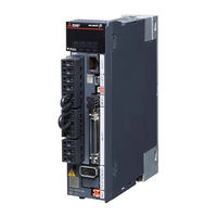
Mitsubishi Electric Melservo MR-J5 G Series User Manual (216 pages)
AC Servo System
Brand:
Mitsubishi Electric
| Category:
Controller
| Size: 20.6 MB
Table of Contents
About the Manual
3
U.s. Customary Units
4
Table of Contents
5
Chapter 1 Servo Amplifier Troubleshooting
9
Outline
9
List of Alarm No./Warning no
11
Explanation of the List
11
Handling Methods for Alarms/Warnings
26
[AL. 010_Undervoltage]
26
[AL. 011_Switch Setting Error]
27
[AL. 012_Memory Error 1 (RAM)]
28
[AL. 013_CPU Error]
29
[AL. 014_Control Process Error]
30
[AL. 016_Encoder Initial Communication Error 1]
31
[AL. 017_Board Error]
33
[AL. 019_Memory Error 3]
35
[AL. 01A_Servo Motor Combination Error]
36
[AL. 01E_Encoder Initial Communication Error 2]
38
[AL. 01F_Encoder Initial Communication Error 3]
39
[AL. 020_Encoder Normal Communication Error 1]
40
[AL. 021_Encoder Normal Communication Error 2]
42
[AL. 024_Main Circuit Error]
43
[AL. 025_Absolute Position Erased]
44
[AL. 027_Initial Magnetic Pole Detection Error]
47
[AL. 028_Linear Encoder Error 2]
49
[AL. 02A_Linear Encoder Error 1]
50
[AL. 02B_Encoder Counter Error]
51
[AL. 030_Regenerative Error]
52
[AL. 031_Overspeed]
53
[AL. 032_Overcurrent]
54
[AL. 033_Overvoltage]
56
[AL. 035_Command Frequency Error]
57
[AL. 037_Parameter Error]
58
[AL. 03A_Inrush Current Suppression Circuit Error]
59
[AL. 042_Servo Control Error]
60
[AL. 045_Main Circuit Device Overheat]
63
[AL. 046_Servo Motor Overheat]
64
[AL. 047_Cooling Fan Error]
66
[AL. 050_Overload 1]
67
[AL. 051_Overload 2]
69
[AL. 052_Excessive Error]
70
[AL. 054_Oscillation Detection]
72
[AL. 056_Forced Stop Error]
73
[AL. 063_STO Timing Error]
74
[AL. 066_Encoder Initial Communication Error (Safety Sub-Function)]
75
[AL. 067_Encoder Normal Communication Error 1 (Safety Sub-Function)]
76
[AL. 068_STO Diagnosis Error]
77
[AL. 069_Command Error]
78
[AL. 070_Load-Side Encoder Initial Communication Error 1]
80
[AL. 071_Load-Side Encoder Normal Communication Error 1]
83
[AL. 072_Load-Side Encoder Normal Communication Error 2]
85
[AL. 076_Load-Side Encoder Error]
86
[AL. 086_Network Communication Error]
87
[AL. 088_Watchdog 1]/[AL. 888_Watchdog 1]/[AL. 88888_Watchdog 1]
88
[AL. 08A_Serial Communication Time-Out Error]
89
[AL. 08E_Serial Communication Error]
90
[AL. 090_Homing Incomplete Warning]
91
[AL. 091_Servo Amplifier Overheat Warning]
92
[AL. 092_Battery Cable Disconnection Warning]
93
[AL. 093_ABS Data Transfer Warning]
94
[AL. 095_STO Warning]
95
[AL. 096_Home Position Setting Warning]
96
[AL. 098_Software Position Limit Warning]
97
[AL. 099_Stroke Limit Warning]
98
[AL. 09B_Excessive Error Warning]
100
[AL. 09E_Network Warning]
101
[AL. 09F_Battery Warning]
103
[AL. 0E0_Excessive Regeneration Warning]
104
[AL. 0E1_Overload Warning 1]
105
[AL. 0E2_Servo Motor Overheat Warning]
107
[AL. 0E3_Absolute Position Counter Warning]
108
[AL. 0E5_ABS Time-Out Warning]
109
[AL. 0E6_Servo Forced Stop Warning]
110
[AL. 0E8_Cooling Fan Speed Reduction Warning]
111
[AL. 0E9_Main Circuit off Warning]
112
[AL. 0EA_ABS Servo-On Warning]
113
[AL. 0Eb_The Other Axis Error Warning]
114
[AL. 0Ec_Overload Warning 2]
115
[AL. 0Ed_Output Watt Excess Warning]
116
[AL. 0F0_Tough Drive Warning]
117
[AL. 0F2_Drive Recorder Warning]
118
[AL. 0F3_Oscillation Detection Warning]
119
[AL. 0F4_Positioning Warning]
120
[AL. 0F7_Machine Diagnosis Warning]
121
[AL. 118_Encoder Diagnosis]
123
[AL. 119_Memory Error 4]
124
[AL. 11A_Servo Motor Constant Error]
125
[AL. 130_Regenerative Error 2]
126
[AL. 139_Open-Phase Error]
127
[AL. 168_STO Function Error]
128
[AL. 17A_Load-Side Linear Encoder Error 1]
129
[AL. 188_Watchdog 2]
130
[AL. 19E_Network Warning 2]
131
[AL. 1E9_Open Phase Warning]
132
[AL. 1F8_Memory Warning 1]
133
[AL. 510_Voltage Diagnosis Error (Safety Sub-Function)]
134
[AL. 512_Memory Error 1 (RAM) (Safety Sub-Function)]
135
[AL. 514_Control Process Error (Safety Sub-Function)]
136
[AL. 515_Memory Error 2 (ROM) (Safety Sub-Function)]
137
[AL. 516_Encoder Initial Communication Error 1 (Safety Sub-Function)]
138
[AL. 517_Board Error (Safety Sub-Function)]
139
[AL. 518_Synchronous Control Error (Safety Sub-Function)]
140
[AL. 519_Memory Error 3 (Flash-ROM) (Safety Sub-Function)]
141
[AL. 520_Encoder Normal Communication Diagnosis Error 1 (Safety Sub-Function)]
143
[AL. 521_Encoder Normal Communication Diagnosis Error 2 (Safety Sub-Function)]
143
[AL. 522_Encoder Normal Communication Diagnosis Error 3 (Safety Sub-Function)]
144
[AL. 523_Encoder Normal Communication Diagnosis Error 4 (Safety Sub-Function)]
145
[AL. 524_Encoder Normal Communication Diagnosis Error 5 (Safety Sub-Function)]
146
[AL. 525_Encoder Normal Communication Diagnosis Error 6 (Safety Sub-Function)]
147
[AL. 526_Encoder Normal Communication Diagnosis Error 7 (Safety Sub-Function)]
148
[AL. 527_Encoder Normal Communication Diagnosis Error 8 (Safety Sub-Function)]
149
[AL. 528_Encoder Normal Communication Diagnosis Error 9 (Safety Sub-Function)]
150
[AL. 529_Encoder Data Error (Safety Sub-Function)]
151
[AL. 52A_Position Feedback Error (Safety Sub-Function)]
152
[AL. 52B_Encoder Thermal Error (Safety Sub-Function)]
153
[AL. 52C_ Encoder Normal Communication Error 10 (Safety Sub-Function)]
154
[AL. 537_Parameter Setting Range Error (Safety Sub-Function)]
155
[AL. 53A_Parameter Verification Error (Safety Sub-Function)]
156
[AL. 540_Internal Diagnosis Error 1 (Safety Sub-Function)]
157
[AL. 541_Internal Diagnosis Error 2 (Safety Sub-Function)]
158
[AL. 542_Internal Diagnosis Error 3 (Safety Sub-Function)]
159
[AL. 543_Internal Diagnosis Error 4 (Safety Sub-Function)]
160
[AL. 544_Temperature Diagnosis Error (Safety Sub-Function)]
161
[AL. 545_Internal Diagnosis Error 5 (Safety Sub-Function)]
162
[AL. 546_Internal Diagnosis Error 6 (Safety Sub-Function)]
163
[AL. 547_Internal Diagnosis Error 7 (Safety Sub-Function)]
164
[AL. 549_Internal Diagnosis Error 8 (Safety Sub-Function)]
165
[AL. 54A_Internal Diagnosis Error 9 (Safety Sub-Function)]
166
[AL. 54D_Internal Diagnosis Error 10 (Safety Sub-Function)]
167
[AL. 54F_Safety Software Error (Safety Sub-Function)]
168
[AL. 550_Internal Diagnosis Error 11 (Safety Sub-Function)]
169
[AL. 551_Internal Diagnosis Error 12 (Safety Sub-Function)]
170
[AL. 552_Internal Diagnosis Error 13 (Safety Sub-Function)]
171
[AL. 554_Input Device Internal Diagnosis Error (Safety Sub-Function)]
172
[AL. 555_Output Device Diagnosis Error 1 (Safety Sub-Function)]
173
[AL. 556_Output Device Diagnosis Error 2 (Safety Sub-Function)]
174
[AL. 557_Input Device Mismatch Detection (Safety Sub-Function)]
175
[AL. 560_Stop Error (Safety Sub-Function)]
176
[AL. 561_Safety Speed Monitor Error 1 (Safety Sub-Function)]
178
[AL. 562_Safety Speed Monitor Error 2 (Safety Sub-Function)]
180
[AL. 563_Deceleration Monitor Error (Safety Sub-Function)]
182
[AL. 564_Increment Monitor Error (Safety Sub-Function)]
184
[AL. 565_Direction Monitor Error (Safety Sub-Function)]
185
[AL. 568_Torque Monitor Error 1 (Safety Sub-Function)]
187
[AL. 569_Torque Monitor Error 2 (Safety Sub-Function)]
189
[AL. 580_Safety Communication Setting Error (Safety Sub-Function)]
191
[AL. 581_Safety Communication Error 1 (Safety Sub-Function)]
192
[AL. 582_Safety Communication Error 2 (Safety Sub-Function)]
194
[AL. 583_Safety Communication Error 3 (Safety Sub-Function)]
195
[AL. 595_STO Command off Warning (Safety Sub-Function)]
196
[AL. 596_SS1 Time-Out Warning (Safety Sub-Function)]
197
[AL. 59D_Internal Diagnosis Error (Safety Sub-Function)]
198
[AL. 5E1_Test Mode Setting Mismatch Warning (Safety Sub-Function)]
199
[AL. 5E2_Safety Communication Warning (Safety Sub-Function)]
200
[AL. 5E6_SS1 Command off Warning (Safety Sub-Function)]
201
Advertisement
Mitsubishi Electric Melservo MR-J5 G Series User Manual (120 pages)
AC Servo System
Brand:
Mitsubishi Electric
| Category:
Amplifier
| Size: 9.92 MB
Table of Contents
Safety Instructions
3
About the Manual
4
Disposal of Waste
4
U.s. Customary Units
6
Table of Contents
7
Chapter 1 Specifications
11
Outline
11
Model Designation
11
Servo Amplifier/Motor Combinations
13
Servo Amplifier Standard Specifications
14
Mr-J5-_G-N1
14
Mr-J5W2-_G-N1
16
Mr-J5W3-_G-N1
17
Functional Safety
18
Environment
19
Function Block Diagram
20
Mr-J5-_G-_N1
20
Mr-J5W_-_G-N1
21
Configuration Including Peripheral Equipment
22
Special Specifications
23
Servo Amplifiers Without the Dynamic Brake (-ED/-RU)
23
Chapter 2 Function
24
Function List
24
Security
33
Chapter 3 Structure
34
Parts Identification
34
Switch Setting and Display of the Servo Amplifier
38
Switches
38
7-Segment LED
39
CN1A/CN1B Connector LED
42
Status Leds
43
LED Display
44
Chapter 4 Startup
45
Turning on Servo Amplifier for the First Time
49
Test Operation of the Servo Motor Alone in Test Operation Mode
50
Equipment Configuration Setting
51
Controller-Related Setting
51
Operation by Controller Command
52
Instructions on Startup
53
Troubleshooting at Startup
53
Duplicate Setting
54
Duplication Using MR Configurator2
54
Test Operation
54
Execution Method
54
Test Operation Mode
55
Motor Driving by Test Operation
55
Motor-Less Operation
58
Output Signal (DO) Forced Output
59
Servo Amplifier Setting Initialization
60
Initialization Procedure by MR Mode Change
60
Chapter 5 Maintenance, Inspection and Parts Replacement
61
Inspection Items
61
Periodic Inspection
61
Parts with a Service Life
61
Replacing Fan Unit
62
Chapter 6 Compliance with Global Standards
63
Compliance with Global Standards
63
Handling of AC Servo Amplifier Batteries for the United Nations Recommendations on the Transport of
63
Dangerous Goods
63
Symbol for the New EU Battery Directive
65
Compliance with China Compulsory Certification (CCC)
66
Compliance with the China Rohs Directive
67
Chapter 7 Servo Parameters
69
Basic Setting Servo Parameters Group ([Pr. PA
69
[Pr. Pa01_Operation Mode (**STY)]
69
Gain/Filter Setting Servo Parameters Group ([Pr. PB
70
[Pr. Pb82_Position Command Smoothing Filtering Time Constant (PFT)]
70
Extension Setting Servo Parameters Group ([Pr. PC
71
[Pr. Pc42_Function Selection C-10 (COP10)]
71
[Pr. Pc43_Forward Rotation Torque Limit 2 (TLP2)]
71
[Pr. Pc44_Reverse Rotation Torque Limit 2 (TLN2)]
72
[Pr. Pc69_Following Error Output Filtering Time (FEWF)]
72
[Pr. Pc71_In-Position 2 - Output Filtering Time (INP2F)]
72
[Pr. Pc73_Speed Reached 2 - Output Filtering Time (SA2F)]
73
[Pr. Pc78_Function Selection C-F (*COPF)]
73
[Pr. Pc81_For Manufacturer Setting]
73
Extension Setting 2 Servo Parameters Group ([Pr. PE
74
[Pr. Pe53_Maximum Torque Limit 1 (TLMX1)]
74
Positioning Control Setting Servo Parameters Group ([Pr. PT
75
[Pr. Pt01_Command Mode Selection (**CTY)]
75
[Pr. Pt53_Torque Slope (TQS)]
75
Network Setting Servo Parameters Group ([Pr. PN
76
[Pr. Pn02_For Manufacturer Setting]
76
[Pr. Pn05_For Manufacturer Setting]
76
[Pr. Pn18_Counter Level for Communication Error Detection (CERN)]
76
[Pr. Pn20_For Manufacturer Setting]
76
Positioning Extension Setting Servo Parameters Group ([Pr. PV
77
[Pr. Pv23_Speed Unit Conversion - Electronic Gear - Numerator (*VCMX)]
77
[Pr. Pv24_Speed Unit Conversion - Electronic Gear - Denominator (*VCDV)]
77
[Pr. Pv25_Acceleration Unit Conversion - Electronic Gear - Numerator (*ACMX)]
77
[Pr. Pv26_Acceleration Unit Conversion - Electronic Gear - Denominator (*ACDV)]
77
Lists of Supported Control Modes
78
Basic Setting Servo Parameters Group ([Pr. PA
79
Gain/Filter Setting Servo Parameters Group ([Pr. PB
80
Extension Setting Servo Parameters Group ([Pr. PC
82
I/O Setting Servo Parameters Group ([Pr. PD
83
Extension Setting 2 Servo Parameters Group ([Pr. PE
84
Extension Setting 3 Servo Parameters Group ([Pr. PF
85
Motor Extension Setting Servo Parameters Group ([Pr. PL
86
Positioning Control Setting Servo Parameters Group ([Pr. PT
87
Network Setting Servo Parameters Group ([Pr. PN
87
Positioning Extension Setting Servo Parameters Group ([Pr. PV
88
Lists of Servo Parameter Initial Values
89
Basic Setting Servo Parameters Group ([Pr. PA
89
Gain/Filter Setting Servo Parameters Group ([Pr. PB
90
Extension Setting Servo Parameters Group ([Pr. PC
92
I/O Setting Servo Parameters Group ([Pr. PD
94
Extension Setting 2 Servo Parameters Group ([Pr. PE
96
Extension Setting 3 Servo Parameters Group ([Pr. PF
98
Motor Extension Setting Servo Parameters Group ([Pr. PL
100
Positioning Control Setting Servo Parameters Group ([Pr. PT
102
Network Setting Servo Parameters Group ([Pr. PN
104
Positioning Extension Setting Servo Parameters Group ([Pr. PV
105
Chapter 8 Network Parameters
106
Network Basic Parameters
106
[Pr. Npa01_For Manufacturer Setting]
106
[Pr. Npa02_For Manufacturer Setting]
106
[Pr. Npa04_For Manufacturer Setting]
106
[Pr. Npa08_For Manufacturer Setting]
106
[Pr. Npa09_Node Address Setting]
106
User Authentication Parameters
107
[Pr. Npb01_For Manufacturer Setting]
107
[Pr. Npb04_For Manufacturer Setting]
107
[Pr. Npb05_For Manufacturer Setting]
107
[Pr. Npb06_For Manufacturer Setting]
107
[Pr. Npb07_For Manufacturer Setting]
107
[Pr. Npb08_For Manufacturer Setting]
107
[Pr. Npb09_For Manufacturer Setting]
107
[Pr. Npb10_For Manufacturer Setting]
107
[Pr. Npb11_For Manufacturer Setting]
107
[Pr. Npb17_For Manufacturer Setting]
108
[Pr. Npb18_For Manufacturer Setting]
108
[Pr. Npb19_For Manufacturer Setting]
108
[Pr. Npb20_For Manufacturer Setting]
108
[Pr. Npb21_For Manufacturer Setting]
108
[Pr. Npb22_For Manufacturer Setting]
108
[Pr. Npb23_For Manufacturer Setting]
108
[Pr. Npb24_For Manufacturer Setting]
108
[Pr. Npb25_For Manufacturer Setting]
108
[Pr. Npb26_For Manufacturer Setting]
108
Chapter 9 Functional Safety Parameters
109
Safety Sub-Function 1 Parameters Group ([Pr. PSA
109
[Pr. Psa01_Safety Sub-Function Mode Selection (**SOA)]
109
[Pr. Psa05_For Manufacturer Setting]
109
[Pr. Psa06_For Manufacturer Setting]
109
[Pr. Psa07_For Manufacturer Setting]
109
[Pr. Psa08_For Manufacturer Setting]
109
[Pr. Psa09_For Manufacturer Setting]
109
[Pr. Psa10_For Manufacturer Setting]
110
[Pr. Psa11_For Manufacturer Setting]
110
[Pr. Psa12_For Manufacturer Setting]
110
[Pr. Psa13_For Manufacturer Setting]
110
[Pr. Psa14_For Manufacturer Setting]
110
[Pr. Psa17_For Manufacturer Setting]
110
[Pr. Psa18_For Manufacturer Setting]
110
[Pr. Psa19_For Manufacturer Setting]
110
[Pr. Psa27_For Manufacturer Setting]
110
[Pr. Psa28_For Manufacturer Setting]
110
Safety Sub-Function 2 Parameters Group ([Pr. PSB
111
[Pr. Psb01_For Manufacturer Setting]
111
[Pr. Psb02_For Manufacturer Setting]
111
[Pr. Psb06_For Manufacturer Setting]
111
[Pr. Psb10_For Manufacturer Setting]
111
[Pr. Psb11_For Manufacturer Setting]
111
[Pr. Psb12_For Manufacturer Setting]
111
[Pr. Psb13_For Manufacturer Setting]
111
[Pr. Psb14_For Manufacturer Setting]
111
[Pr. Psb15_For Manufacturer Setting]
111
Network Parameters Group ([Pr. PSC
112
[Pr. Psc01_For Manufacturer Setting]
112
[Pr. Psc03_For Manufacturer Setting]
112
[Pr. Psc06_For Manufacturer Setting]
112
Safety I/O Device Parameters Group ([Pr. PSD
113
[Pr. Psd01_For Manufacturer Setting]
113
[Pr. Psd02_Input Device Selection DI1 (**SDI1)]
113
[Pr. Psd08_Output Device Selection DO1 (**SDO1)]
115
Lists of Functional Safety Parameter Initial Values
115
Revisions
116
Warranty
117
Trademarks
118
Mitsubishi Electric Melservo MR-J5 G Series User Manual (74 pages)
AC Servo System
Brand:
Mitsubishi Electric
| Category:
Amplifier
| Size: 8.77 MB
Table of Contents
Safety Instructions
3
Disposal of Waste
4
About the Manual
5
U.s. Customary Units
6
Table of Contents
7
Chapter 1 Specifications
9
Outline
9
Model Designation
9
Servo Amplifier/Motor Combinations
11
Servo Amplifier Standard Specifications
12
Mr-J5-_G
12
Mr-J5W2-_G
14
Mr-J5W3-_G
15
Functional Safety
16
Environment
19
Function Block Diagram
20
Mr-J5-_G
20
Mr-J5W_-_G
21
Configuration Including Peripheral Equipment
22
Special Specifications
23
Servo Amplifiers Without the Dynamic Brake (-ED/-RU)
23
Chapter 2 Function
24
Function List
24
Security
35
Chapter 3 Structure
36
Parts Identification
36
Switch Setting and Display of the Servo Amplifier
40
Switches
40
7-Segment LED
41
CN1A/CN1B Connector LED
44
Status Leds
45
Chapter 4 Startup
46
Turning on Servo Amplifier for the First Time
50
Test Operation of the Servo Motor Alone in Test Operation Mode
51
Equipment Configuration Setting
52
Controller-Related Setting
52
Operation by Controller Command
53
Instructions on Startup
54
Troubleshooting at Startup
54
Duplicate Setting
55
Duplication Using MR Configurator2
55
Test Operation
55
Execution Method
55
Test Operation Mode
56
Motor Driving by Test Operation
56
Motor-Less Operation
59
Output Signal (DO) Forced Output
60
Servo Amplifier Setting Initialization
61
Initialization Procedure by MR Mode Change
61
Chapter 5 Maintenance, Inspection and Parts Replacement
62
Inspection Items
62
Periodic Inspection
62
Parts with a Service Life
62
Replacing Fan Unit
63
Chapter 6 Compliance with Global Standards
64
Compliance with Global Standards
64
Advertisement
Related Products
Mitsubishi Electric MR-J5W-G Series
Mitsubishi Electric MR-J5-G Series
Mitsubishi Electric MR-J5-A Series
Mitsubishi Electric Melservo MR-J5W G Series
Mitsubishi Electric MELSERVO MR-J5W2 G-N1 Series
Mitsubishi Electric MELSERVO MR-J5W3 G-N1 Series
Mitsubishi Electric MR-J3W-0303BN6
Mitsubishi Electric MR-J2S-20CP-S084 1
Mitsubishi Electric MELSERVO MR-J2-70A
Mitsubishi Electric MELSERVO MR-J2-40A
Mitsubishi Electric Categories
Air Conditioner
Controller
Projector
Inverter
Heat Pump
More Mitsubishi Electric Manuals
Login
Sign In
OR
Sign in with Facebook
Sign in with Google
Upload manual
Upload from disk
Upload from URL