Sign In
Upload
Manuals
Brands
Meru Networks Manuals
Wireless Access Point
RS4000
Meru Networks RS4000 Outdoor WiFi Switch Manuals
Manuals and User Guides for Meru Networks RS4000 Outdoor WiFi Switch. We have
2
Meru Networks RS4000 Outdoor WiFi Switch manuals available for free PDF download: Installation Manual
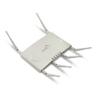
Meru Networks RS4000 Installation Manual (145 pages)
Access Point and Radio Switch
Brand:
Meru Networks
| Category:
Wireless Access Point
| Size: 2.67 MB
Table of Contents
Table of Contents
3
About this Guide
11
Audience
11
In this Guide
11
Other Sources of Information
12
Meru Publications
12
External References
12
Typographic Conventions
12
Contacting Meru
13
Customer Services and Support
13
Chapter 1 Meru Access Points and Radio Switch
15
Meru Access Point AP300 Series
15
Figure 1 Meru AP 300
16
Meru Access Point AP200 Series
17
Figure 2 Access Point AP200
17
Meru Access Point AP150 Series
18
Meru Access Point OAP180
19
Figure 3 Access Point AP150
19
Radio Switch RS4000
20
Figure 4 Rugged OAP180 Access Point
20
Figure 5 Radio Switch RS4000
21
RS4000 Hardware Features and Specifications
21
Table 1 RS4000 Hardware Features
22
Chapter 2 Installing the AP300
25
Safety Precautions
25
Unpack the AP300
26
Table 2 Meru AP300 Radios and Antennas
26
Determine Power Requirements
27
Installation Requirements
27
Table 3 AP300 Power Options
27
Additional Equipment
28
Table 4 AP300 Installation Items
28
Install the AP300
29
Select a Location
29
Attach the Antennas
29
Figure 6 AP320, AP311 or AP302 Antennas 1-6
30
Table 5 Antenna Use for AP320, AP311, and AP302 (Dual Radio Units)
30
Figure 7 AP310 Antennas 1-3
31
Figure 8 AP300 Antenna Connection
31
Table 6 Antenna Use for AP310 (Single Radio Unit)
31
Figure 9 Remote Antenna Mount
32
Install the Access Point
33
Figure 10 Mounting the AP300 to a Suspended Ceiling Rail
35
Figure 11 AP300 Mounted above a Suspended Ceiling
36
Figure 12 Attaching the Mounting Bracket to the Box Hanger
37
Check AP300 LED Activity
38
Figure 13 AP300 Status Leds
38
Table 7 AP300 LED Descriptions
39
Chapter 3 Installing the AP200
41
Safety Precautions
41
Unpacking the AP200
41
Installation Requirements
42
Figure 14 AP200 Mounting Bracket
42
Table 8 AP200 Installation Items
43
Installing the Access Points
44
Selecting a Location
44
Table 9 AP200 Installation Tools
44
Attaching the AP200 Antennas
45
Mounting the Access Point
45
Figure 15 AP200 Antenna Connection
46
Figure 16 AP200 Connector Panel
47
Figure 17 AP200 Bracket
47
Figure 18 Aligning the AP200 with the Bracket
48
Figure 19 Sliding the AP200 into the Bracket
49
Figure 20 Mounting the AP200 to a Suspended Ceiling Rail
50
Figure 21 Mounting the AP200 above a Suspended Ceiling
52
Figure 22 Box Hanger Mounting Bracket Holes
52
Figure 23 Attaching the Mounting Bracket to the Box Hanger
53
Where to Go from here
54
Checking LED Activity
55
Ethernet Connector Leds
55
Figure 24 RJ-45 Leds
55
AP200 Status Leds
56
Figure 25 AP200 Status Leds
56
Table 10 AP200 LED Descriptions
57
Table 11 AP200 Controller Status Information
57
Chapter 4 Installing the OAP180
59
Safety Precautions
59
Unpacking the OAP180
60
Installation Requirements
60
Figure 26 OAP180 Outdoor Access Point
60
Installing the Access Points
61
Selecting a Location
61
Figure 27 Sample Physical Layout
61
Test Basic Link Operation
63
Mounting the Access Point
63
Figure 28 Square Mounting Bracket Attaches to Bottom of OAP180
63
Figure 29 Brackets Attached to a Pole
64
Connect Antennas and Ground Wire to OAP180
65
Figure 30 Connect the Antenna Cables
66
Align Antenna
68
Where to Go from here
69
Checking LED Activity
69
Antenna Gain Recommendations
70
Figure 31 OAP180 Leds
70
Table 12 Antenna Gain
71
Chapter 5 Installing the AP150
73
Safety Precautions
73
Unpacking the AP150
73
Installation Requirements
74
Figure 32 AP150 with Mounting Bracket
74
Table 13 AP150 Installation Items
75
Installing the Access Points
76
Selecting a Location
76
Table 14 AP150 Installation Tools
76
Attaching the AP150 Antennas
77
Mounting the Access Point
77
Figure 33 AP150 Antenna Connection
78
Figure 34 AP150 Connector Panel
78
Figure 35 AP150 Bracket
80
Figure 36 Aligning the AP150 with the Bracket
81
Figure 37 Mounting the AP150 to a Suspended Ceiling Rail
82
Where to Go from here
83
Checking LED Activity
84
AP150 Status Leds
84
Figure 38 AP150 Status Leds
84
Table 15 AP150 LED Descriptions
85
Chapter 6 Installing the RS4000
87
Safety Precautions
87
Unpacking the RS4000
87
Installation Requirements
88
Figure 39 RS4000 Package Contents
88
About an Hoffman/Nema Enclosure Installation
90
Table 16 RS4000 Installation Tools
90
Figure 40 Open NEMA Box Showing Mounting Holes
91
Optimum Antenna Positioning and Placement
91
Installing the RS4000
92
Mounting the RS4000
92
Figure 41 Bracket Attached to RS4000
93
Figure 42 RS4000 Bracket Mounting
94
Figure 43 RS4000 with Antenna Attached
95
Figure 44 Mounting the RS4000 below a Suspended Ceiling Rail
96
Figure 45 RS4000 with Antenna Attached
97
Figure 46 Mounting the RS4000 above a Suspended Ceiling
98
Figure 47 Box Hanger Mounting Bracket Holes
99
Figure 48 Attaching the Mounting Bracket to the Box Hanger
99
Figure 49 RS4000 with Antenna Attached
100
Placing and Positioning the Antenna
101
Figure 50 RS4000
101
Figure 51 Antenna Mounting Arm with Wall Bracket (Shown Attached)
102
Figure 52 Antenna Ceiling Tile Rail Base
102
Hoffman/Nema Enclosure RS4000 Installation
103
Figure 53 RS4000 and Antenna Installed in NEMA Enclosure
104
Where to Go from here
105
Checking LED Activity
106
RS4000 Status Leds
106
Figure 54 RS4000 Status Leds
106
Table 17 RS4000 LED Descriptions
107
Appendix A Specifications
109
Wireless Interface
109
Table 18 Wireless Interface Specifications
109
Ethernet Interface
111
Physical
111
Appendix Bap Accessories
113
AP300 Accessories
113
AP300 Poe Devices
113
AP300 Power Supply
113
AP300 Antennas
114
AP300 Mounting Options
114
AP200 Accessories
115
OAP1800 Accessories
115
AP150 Accessories
115
Appendix C Mounting Bracket Stencils
117
AP150 and AP300 Rev a Mounting Bracket Stencil
117
AP300 Rev B Mounting Bracket Stencil
119
Appendix D Cautions and Warnings
121
Cautions
121
Warnings
124
Appendix E Regulatory Information
129
For OAP180
129
Radio
129
Emc
129
Safety
129
Usa
130
Underwriters Laboratories
130
FCC Radiation Exposure Statement
131
Radio Frequency Interference Requirements
131
Canada. Industry Canada (IC)
133
Europe-EU Declaration of Conformity and Restrictions
135
IEEE 802.11A Restrictions
137
EEE 802.11B/G Restrictions
138
Japan
138
Singapore
139
Manufacturing Information
139
AP300 Plenum Requirements
140
Advertisement
Meru Networks RS4000 Installation Manual (93 pages)
Access Point and Radio Switch
Brand:
Meru Networks
| Category:
Wireless Access Point
| Size: 2.25 MB
Table of Contents
Installation Guide
1
Table of Contents
3
List of Figures
5
List of Tables
7
About this Guide
9
Audience
9
In this Guide
9
Other Sources of Information
10
Meru Publications
10
External References
10
Typographic Conventions
10
Contacting Meru
11
Customer Services and Support
11
Chapter 1 Meru Access Points and Radio Switch
13
Introducing the Radio Switch RS4000
13
Figure 1 Radio Switch RS4000
14
RS4000 Hardware Features and Specifications
15
Table 1 RS4000 Hardware Features
15
Meru Access Point Features
17
Introducing the Meru Access Point AP200
17
Introducing the Meru Access Point AP150
18
Figure 2 Access Point AP200
18
Figure 3 Access Point AP150
19
Chapter 2 Installing the RS4000
21
Safety Precautions
21
Unpacking the RS4000
21
Installation Requirements
22
Figure 4 RS4000 Package Contents
22
About an Hoffman/Nema Enclosure Installation
24
Table 2 RS4000 Installation Tools
24
Figure 5 Open NEMA Box Showing Mounting Holes
25
Optimum Antenna Positioning and Placement
25
Installing the RS4000
26
Mounting the RS4000
26
Figure 6 Bracket Attached to RS4000
27
Figure 7 RS4000 Bracket Mounting
28
Figure 8 RS4000 with Antenna Attached
29
Figure 9 Mounting the RS4000 below a Suspended Ceiling Rail
30
Figure 10 RS4000 with Antenna Attached
31
Figure 11 Mounting the RS4000 above a Suspended Ceiling
32
Figure 12 Box Hanger Mounting Bracket Holes
33
Figure 13 Attaching the Mounting Bracket to the Box Hanger
33
Figure 14 RS4000 with Antenna Attached
34
Placing and Positioning the Antenna
35
Figure 15 RS4000 180 O Directional Antenna
35
Figure 16 Antenna Mounting Arm with Wall Bracket (Shown Attached)
36
Figure 17 Antenna Ceiling Tile Rail Base
36
Hoffman/Nema Enclosure RS4000 Installation
37
Figure 18 RS4000 and Antenna Installed in NEMA Enclosure
38
Where to Go from here
39
Checking LED Activity
40
RS4000 Status Leds
40
Figure 19 RS4000 Status Leds
40
Table 3 RS4000 LED Descriptions
41
Chapter 3 Installing the AP200
43
Safety Precautions
43
Unpacking the AP200
43
Installation Requirements
44
Figure 20 AP200 Mounting Bracket
44
Table 4 AP200 Installation Items
45
Installing the Access Points
46
Selecting a Location
46
Table 5 AP200 Installation Tools
46
Attaching the AP200 Antennas
47
Mounting the Access Point
47
Figure 21 AP200 Antenna Connection
48
Figure 22 AP200 Connector Panel
48
Figure 23 AP200 Bracket
49
Figure 24 Aligning the AP200 with the Bracket
50
Figure 25 Sliding the AP200 into the Bracket
50
Figure 26 Mounting the AP200 to a Suspended Ceiling Rail
51
Figure 27 Mounting the AP200 above a Suspended Ceiling
53
Figure 28 Box Hanger Mounting Bracket Holes
53
Figure 29 Attaching the Mounting Bracket to the Box Hanger
54
Where to Go from here
55
Checking LED Activity
55
Ethernet Connector Leds
55
Figure 30 RJ-45 Leds
55
AP200 Status Leds
56
Figure 31 AP200 Status Leds
56
Table 6 AP200 LED Descriptions
57
Table 7 AP200 Controller Status Information
57
Chapter 4 Installing the AP150
59
Safety Precautions
59
Unpacking the AP150
59
Installation Requirements
60
Figure 32 AP150 with Mounting Bracket
60
Table 8 AP150 Installation Items
61
Installing the Access Points
62
Selecting a Location
62
Table 9 AP150 Installation Tools
62
Attaching the AP150 Antennas
63
Mounting the Access Point
63
Figure 33 AP150 Antenna Connection
64
Figure 34 AP150 Connector Panel
64
Figure 35 AP150 Bracket
66
Figure 36 Aligning the AP150 with the Bracket
67
Figure 37 Mounting the AP150 to a Suspended Ceiling Rail
68
Where to Go from here
69
Checking LED Activity
70
AP150 Status Leds
70
Figure 38 AP150 Status Leds
70
Table 10 AP150 LED Descriptions
71
Appendix A Specifications
73
Wireless Interface
73
Table 11 Wireless Interface Specifications
73
Ethernet Interface
74
Physical
74
Appendix B Regulatory Information
75
Usa
75
Underwriters Laboratories
75
FCC Radiation Exposure Statement
76
Radio Frequency Interference Requirements
76
Canada. Industry Canada (IC)
77
Europe-EU Declaration of Conformity and Restrictions
79
IEEE 802.11A Restrictions
81
EEE 802.11B/G Restrictions
81
Japan
82
Manufacturing Information
82
Appendix C Channels
83
Channels
83
IEEE 802.11A
83
Table 12 IEEE 802.11A Channels
83
IEEE 802.11B/G
85
Table 13 IEEE 802.11B/G Channels
85
Appendix D Mounting Bracket Stencils
87
AP150 Mounting Bracket Stencil
87
Advertisement
Related Products
Meru Networks AP100
Meru Networks AP100-P
Meru Networks AP1000 SERIES
Meru Networks AP1010i
Meru Networks AP1014i
Meru Networks AP1020i
Meru Networks AP110 series
Meru Networks AP150
Meru Networks Categories
Wireless Access Point
Mobility Aid
Wheelchair
Adapter
Controller
More Meru Networks Manuals
Login
Sign In
OR
Sign in with Facebook
Sign in with Google
Upload manual
Upload from disk
Upload from URL