Table of Contents

Related Manuals for Meru Networks AP320


Summary of Contents for Meru Networks AP320
- Page 1 Internal Use Only—Beta Draft Meru Access Point and Radio Switch Installation Guide Copyright © Meru Networks, Inc., 2003–2008. All rights reserved. Other names and brands may be claimed as the property of others. Document Number: 3.6_ap_install_revA2...
- Page 2 Internal Use Only—Beta Draft...
-
Page 3: Table Of Contents
....31 Mounting the Access Point ....31 © 2008 Meru Networks, Inc. Contents... - Page 4 Checking LED Activity ....RS4000 Status LEDs ....© 2008 Meru Networks, Inc. Meru Access Point and Radio Switch Installation Guide...
- Page 5 Manufacturing Information ....AP300 Plenum Requirements ....© 2008 Meru Networks, Inc. Contents...
- Page 6 © 2008 Meru Networks, Inc. Meru Access Point and Radio Switch Installation Guide...
- Page 7 Figure 3 Access Point AP150 ............... 5 Figure 4 Rugged OAP180 Access Point ............ 6 Figure 5 Radio Switch RS4000 .............. 7 Figure 6 AP320, AP311 or AP302 Antennas 1-6 .......... 16 Figure 7 AP310 Antennas 1-3 ............... 17 Figure 8 AP300 Antenna Connection ............17 Figure 9 Remote Antenna Mount ............
- Page 8 Figure 52 Antenna Ceiling Tile Rail Base ..........88 Figure 53 RS4000 and Antenna Installed in NEMA Enclosure ......90 Figure 54 RS4000 Status LEDs .............. 92 viii © 2008 Meru Networks, Inc. Meru Access Point and Radio Switch Installation Guide...
- Page 9 AP300 Power Options ............. 13 Table 4 AP300 Installation Items ..........14 Table 5 Antenna Use for AP320, AP311, and AP302 (Dual Radio Units) ..16 Table 6 Antenna Use for AP310 (Single Radio Unit)......17 Table 7 AP300 LED Descriptions ..........25 Table 8 AP200 Installation Items ..........
- Page 10 Internal Use Only—Beta Draft © 2008 Meru Networks, Inc. Meru Access Point and Radio Switch Installation Guide...
-
Page 11: About This Guide
Chapter 4, “Installing the OAP180” Chapter 5, “Installing the AP150” Appendix A, “Specifications” Appendix D, “Cautions and Warnings” Appendix E, “Regulatory Information” Appendix D, “Channels” Appendix C, “Mounting Bracket Stencils” Appendix B, “AP Accessories” © 2008 Meru Networks, Inc. About This Guide... -
Page 12: Other Sources Of Information
Caution! damage to or loss of data, or could cause the application to behave in unexpected ways. Identifies critical information about actions that could result in Warning! equipment failure or bodily harm. © 2008 Meru Networks, Inc. About This Guide... -
Page 13: Contacting Meru
Internal Use Only—Beta Draft Contacting Meru You can visit Meru Networks, Inc. on the Internet at this URL: http://www.merunetworks.com Customer Services and Support For assistance, contact Meru Customer Services and Support 24 hours a day at +1-888-637-8952 (+1-888-Meru-WLA(N)) or +1-408-215-5305. Email can be sent to support@merunetworks.com. - Page 14 Internal Use Only—Beta Draft © 2008 Meru Networks, Inc. About This Guide...
-
Page 15: Chapter 1 Meru Access Points And Radio Switch
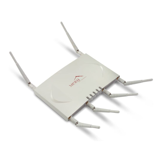
The AP300 Access Point delivers high performance, full-speed, Wi-Fi certified 802.11n based on draft 2.0 connectivity while simultaneously supporting legacy 802.11a/b/g devices. Meru AP300 is available in these configurations: AP320: Two dual-band 802.11n radios with 3x3 MIMO — AP310: Single dual-band 802.11n radio with 3x3 MIMO —... -
Page 16: Figure 1 Meru Ap 300
Internal Use Only—Beta Draft AP311: Single dual-band 802.11n radio and single 802.11a/b/g radio (AP320 — upgradeable) AP302: Two dual-band 802.11a/b/g radios (AP320 upgradeable) — Features for the AP300 include: 802.11n support with channel bonding in both 2.4GHz and 5GHz frequency bands. -
Page 17: Meru Access Point Ap200 Series
AP201 or AP208) is housed in a metal case with a plastic remov- able cover. As such, it can be used for plenum installations when the plastic cover is removed. Figure 2: Access Point AP200 © 2008 Meru Networks, Inc. Meru Access Points and Radio Switch... -
Page 18: Meru Access Point Ap150 Series
Automatic AP discovery, configuration Intelligent load balancing of clients Layer 2 or 3 connectivity for flexible deployment options Locking mechanism secures access point when mounted in public areas © 2008 Meru Networks, Inc. Meru Access Points and Radio Switch... -
Page 19: Meru Access Point Oap180
Full support of System Director features Automatic AP discovery and configuration No channel planning required with single channel installations Intelligent load balancing of clients PoE (Power over Ethernet) support RoHS compliant © 2008 Meru Networks, Inc. Meru Access Points and Radio Switch... -
Page 20: Radio Switch Rs4000
RF channel such that users receive a switched wireless experience with dedicated bandwidth to execute a variety of applications ranging from web browsing and VoIP mobility to multimedia streaming. © 2008 Meru Networks, Inc. Meru Access Points and Radio Switch... -
Page 21: Rs4000 Hardware Features And Specifications
The RS4000 connects to the LAN using one 10/100 Mbps Ethernet connection for each radio pair. The RS4000 is powered using two IEEE 802.3af POE connections, each with 15W power. © 2008 Meru Networks, Inc. Meru Access Points and Radio Switch... -
Page 22: Table 1 Rs4000 Hardware Features
Power, Radio Activity, and Ethernet LEDs Activity LEDs per radio Dimensions 9.5" x 8.5" x 3.875" RS4000 has mounting brackets available for: Ceiling Mount Mounting Options Wall Mount Inside NEMA Enclosures (Hoffman, etc.) © 2008 Meru Networks, Inc. Meru Access Points and Radio Switch... - Page 23 Wideband RF Combination/Omni- Antenna Directional (WRC/OD) Antenna. 5dBi gain. Indoor use. 180-degree directional indoor antenna 3’ low-loss cables (default option) Antenna Cables 6’ and plenum-rated cables (available option) © 2008 Meru Networks, Inc. Meru Access Points and Radio Switch...
- Page 24 Internal Use Only—Beta Draft Radio Switch RS4000 Meru Access Point and Radio Switch Installation Guide © 2008 Meru Networks, Inc.
-
Page 25: Chapter 2 Installing The Ap300
IMPORTANT—Read and follow the regulatory instructions in Appendix E before installing and operating this product. If an optional power supply is used, it should be a UL Listed power supply, marked Class 2 or LPS, and rated minimum 5 Vdc, 3A. © 2008 Meru Networks, Inc. Installing the AP300... -
Page 26: Unpack The Ap300
3 dual band omni- AP302 directional antennas directional antennas Confirm that the AP300 shipping package contains these items: AP300 with attached mounting bracket Six (AP320, AP311, AP302) or three (AP310) antennas © 2008 Meru Networks, Inc. Installing the AP300... -
Page 27: Determine Power Requirements
The AP300 has a security cable slot so you can lock the AP300 with a standard security cable, such as those used to secure laptop computers. These two kits can be used to mount the AP300 from the ceiling: Suspended Ceiling Rail Mounting Kit Above Suspended Ceiling Mounting Kit (T-Bar Hanger) © 2008 Meru Networks, Inc. Installing the AP300... -
Page 28: Additional Equipment
A power source is needed to power the AP300. Available options are: External ACC-AP300-PWR power supply 802.3af compliant PoE device Draft 802.3at compliant PoE device You can optionally add a remote antenna mount; see Install the Optional Remote Antenna Mount on the Ceiling. © 2008 Meru Networks, Inc. Installing the AP300... -
Page 29: Install The Ap300
Place access points accordingly. Attach the Antennas The AP320, AP311, and AP302 have six external antenna ports, labeled 1 - 6. These units only operate with six attached antennas, even though some configurations don’t use all six. Make sure that all external antennas and their associated wiring are located entirely indoors. -
Page 30: Figure 6 Ap320, Ap311 Or Ap302 Antennas 1-6
Figure 6: AP320, AP311 or AP302 Antennas 1-6 The following antenna connections are used during operation of the AP320, AP311, and AP302. Table 5: Antenna Use for AP320, AP311, and AP302 (Dual Radio Units) Mode Radio 1 Uses Radio 2 Uses... -
Page 31: Figure 7 Ap310 Antennas 1-3
Attach the antennas to the connectors on the AP300 (see Figure 8). Rotate the knurled ring at the base of the antenna clockwise to attach the antenna. The ring should be finger-tight. Figure 8: AP300 Antenna Connection antenna connector © 2008 Meru Networks, Inc. Installing the AP300... -
Page 32: Figure 9 Remote Antenna Mount
Mount is suitable for a ceiling mount, but you can attach the Mount to a wall with some modifications. Use one mount per radio; for example AP310 needs one unit, and AP320 needs two units.The Antenna Mount uses low-loss Plenum rated LMR195 cable and SMA connectors. -
Page 33: Install The Access Point
You can mount an AP300 in the following ways: Mount AP300 Horizontally on a Shelf Mount AP300 Vertically on a Wall Mount AP300 Below a Suspended Ceiling Mount AP300 Above a Suspended Ceiling (Plenum) © 2008 Meru Networks, Inc. Installing the AP300... - Page 34 The optional suspended ceiling mounting kit allows the AP300 mounting bracket to attach to suspended ceiling T-rails (see Figure 10). To comply with NEC code, attach a grounding wire to any of the screws used to attach the AP300 Note: to the mounting bracket. © 2008 Meru Networks, Inc. Installing the AP300...
-
Page 35: Figure 10 Mounting The Ap300 To A Suspended Ceiling Rail
10. Connect one end of the PoE 100BaseT Ethernet cable to the 100/1000 Ethernet connector. Be sure to connect the Ethernet cable to the Ethernet port; the cable can Caution! mistakenly be plugged into the Console port. © 2008 Meru Networks, Inc. Installing the AP300... -
Page 36: Figure 11 Ap300 Mounted Above A Suspended Ceiling
1. Determine the location on the ceiling rails where the AP will be mounted and remove the ceiling tile. 2. Unpack the T-bar hanger kit and unfold the legs of the T-bar hanger. © 2008 Meru Networks, Inc. Installing the AP300... -
Page 37: Figure 12 Attaching The Mounting Bracket To The Box Hanger
To mount an AP300 in a Hoffman enclosure, follow these steps: 1. Place AP300 upside down on a soft flat surface. 2. Remove and discard the wall/ceiling mounting bracket (650-00064) if installed. © 2008 Meru Networks, Inc. Installing the AP300... -
Page 38: Check Ap300 Led Activity
Thereafter, the Status LED color reflects the various operating states described in Table After the AP300 is connected, check the status of the LEDs. Figure 13: AP300 Status LEDs The functions of the five LEDs are described below. © 2008 Meru Networks, Inc. Installing the AP300... -
Page 39: Table 7 Ap300 Led Descriptions
OK (at any speed) green/blinking—activity (at any speed) red—auto negotiation failure off—no radio present green—radio enabled Radio 1 green blinking—data activity Radio 2 yellow—disabled or in scanning mode red—failure © 2008 Meru Networks, Inc. Installing the AP300... - Page 40 Check AP300 LED Activity Meru AP300 Installation Guide © 2008 Meru Networks, Inc.
-
Page 41: Chapter 3 Installing The Ap200
AP100. The AP200 has a security cable slot so you can secure the AP200 with a Note: standard security cable, such as those used to secure laptop computers. © 2008 Meru Networks, Inc. Installing the AP200... -
Page 42: Installation Requirements
Electric Code and Sections 2- 128.12 - 010 (3) and 12 - 100 of the Canadian Electrical Code. Part 1. C22. 1. For other countries, consult local authorities for regulations. Meru Access Point and Radio Switch Installation Guide © 2008 Meru Networks, Inc. -
Page 43: Table 8 Ap200 Installation Items
Two keps nuts (with attached lock washer) Mounting bracket Two T-rail clips One T-box hanger Mounting above a ceiling tile (AP200 metal enclosure only) One bracket mounting clip Mounting bracket © 2008 Meru Networks, Inc. Installing the AP200... -
Page 44: Installing The Access Points
For an external power supply connection, ensure the power source is near to where the AP200 will be mounted. Meru Access Point and Radio Switch Installation Guide © 2008 Meru Networks, Inc. -
Page 45: Attaching The Ap200 Antennas
Vertically, as described in the “Vertical Mounting” section. Below a hanging ceiling, as described in the “Mounting Below a Suspended Ceiling” section. Above a tiled hanging ceiling, as described in the “Mounting Above a Suspended Ceiling” section. © 2008 Meru Networks, Inc. Installing the AP200... -
Page 46: Figure 15 Ap200 Antenna Connection
Caution! Be sure to connect the Ethernet cable to the Ethernet port; the cable can mistakenly be plugged into the Console port (see Figure 16). Meru Access Point and Radio Switch Installation Guide © 2008 Meru Networks, Inc. -
Page 47: Figure 16 Ap200 Connector Panel
Ceiling mount hole Access point mount Wall cable access Access point mount Locking detent Suspended ceiling cable access Access point mount Ceiling mount hole Figure 17: AP200 Bracket © 2008 Meru Networks, Inc. Installing the AP200... -
Page 48: Figure 18 Aligning The Ap200 With The Bracket
AP in and slide the AP down until it engages with the locking detents. You should hear it snap in place. Mounting bracket attached to wall Figure 18: Aligning the AP200 with the Bracket Meru Access Point and Radio Switch Installation Guide © 2008 Meru Networks, Inc. -
Page 49: Figure 19 Sliding The Ap200 Into The Bracket
Be sure to connect the Ethernet cable to the Ethernet port; the cable can Caution! mistakenly be plugged into the Console port. © 2008 Meru Networks, Inc. Installing the AP200... -
Page 50: Figure 20 Mounting The Ap200 To A Suspended Ceiling Rail
6. Align the mounting bracket keyholes with the caddy fastener studs and slide the AP200 to the narrow end of the hole. 7. Attach a keps nut to each caddy fastener stud and hand tighten. Do not overtighten. Meru Access Point and Radio Switch Installation Guide © 2008 Meru Networks, Inc. - Page 51 AP200 metal case for installations above a suspended ceiling. Additionally, you must use Ethernet cable that meets the requirements for operating in plenums and environmental air space (in accordance with Section 300-22(C) of the NEC). © 2008 Meru Networks, Inc. Installing the AP200...
-
Page 52: Figure 21 Mounting The Ap200 Above A Suspended Ceiling
One hole attaches the bracket perpendicular to the box hanger; the other mounts the bracket parallel to the box hanger. Mounting bracket holes Figure 22: Box Hanger Mounting Bracket Holes Meru Access Point and Radio Switch Installation Guide © 2008 Meru Networks, Inc. -
Page 53: Figure 23 Attaching The Mounting Bracket To The Box Hanger
11. For each antenna, loosen the knurled ring at the base of the antenna (see Figure 15), point the antenna down, then retighten the ring. 12. Connect one end of the PoE 100BaseT Ethernet cable to the 100/1000 Ethernet connector, shown in Figure © 2008 Meru Networks, Inc. Installing the AP200... -
Page 54: Where To Go From Here
Guide for instructions on initializing the controller and connecting the controller and APs to the Ethernet switch to form the WLAN. Return to this chapter to check the status of the LEDs once the WLAN is operational. Meru Access Point and Radio Switch Installation Guide © 2008 Meru Networks, Inc. -
Page 55: Checking Led Activity
Ethernet activity, the LED is off. The LED on the right is solid green if an Ethernet link is present. If no Ethernet link is present or connectivity is lost, the LED is off. © 2008 Meru Networks, Inc. Installing the AP200... -
Page 56: Ap200 Status Leds
When the AP is first powered up, all LEDs are green. Thereafter, the Status LED (see Figure 25) color reflects the various operating states (Table 11). Meru Access Point and Radio Switch Installation Guide © 2008 Meru Networks, Inc. -
Page 57: Table 10 Ap200 Led Descriptions
AP and the switch or the switch and the controller is unbroken. Blue/Blue/Blue/R Connected Normal operation without security. Blue/Blue/Blue/R ed, for 2 seconds. Authenticated Normal operation with security. Blue blink © 2008 Meru Networks, Inc. Installing the AP200... - Page 58 Access point is in an error state. Red (blinking or Error State solid) Call Meru technical support a. The AP200 LEDs cycle from bright to dim for each “blink.” Meru Access Point and Radio Switch Installation Guide © 2008 Meru Networks, Inc.
-
Page 59: Installing The Oap180
This product is intended to be supplied by a UL Listed power supply, marked Class 2 or LPS, and rated minimum 5 Vdc, 3A. The OAP180 is not certified for plenum installations, and should not be Caution! installed in the plenum space. © 2008 Meru Networks, Inc. Installing the OAP180... -
Page 60: Unpacking The Oap180
PoE does not resend the traffic, it only provides power. Power injector with power cord Installation Requirements In addition to the hardware supplied by Meru Networks, you need the following: Required Standard Ethernet cable to connect the power injector to a switch or controller Antennas (sold separately) -
Page 61: Installing The Access Points
Avoiding radio interference is an important part of wireless planning. Interference is caused by other radio transmissions using the same or an adjacent channel frequency. You should first scan your proposed site using a spectrum analyzer to determine if there are © 2008 Meru Networks, Inc. Installing the OAP180... - Page 62 The shield of the ethernet cable needs to be grounded at the lightning arrestor. If, by design, the lightning arrestor cannot provide this ground, the shield of the ethernet cable will need to be grounded by the installer. Meru Access Point and Radio Switch Installation Guide © 2008 Meru Networks, Inc.
-
Page 63: Test Basic Link Operation
2. Place the V-shaped part of the bracket around the pole and tighten the securing nuts just enough to hold the bracket to the pole. (The bracket may need to be rotated around the pole during the alignment process.) © 2008 Meru Networks, Inc. Installing the OAP180... -
Page 64: Figure 29 Brackets Attached To A Pole
3. Use the included nuts to tightly secure the to the bracket. OAP180 4. Connect the two brackets as shown below. Meru Access Point and Radio Switch Installation Guide © 2008 Meru Networks, Inc. -
Page 65: Connect Antennas And Ground Wire To Oap180
The OAP180 works both with antennas that attach to the unit and remote antennas. When using antennas that attach to the unit, attach the antenna before installing the unit. Use the two connectors on the right (5G-1 and 2.4G-1) as indicated in Figure 8. When deploy- © 2008 Meru Networks, Inc. Installing the OAP180... -
Page 66: Figure 30 Connect The Antenna Cables
Use only the provided Ethernet cable. Do not shorten this cable as the path loss is needed. During periods of lightning activity, do not connect or disconnect cables or otherwise work with the OAP180. Meru Access Point and Radio Switch Installation Guide © 2008 Meru Networks, Inc. - Page 67 Note: Each AC power injector requires 1.5 amps of power at 100-240 volts. When connecting multiple devices to one outlet, be sure to allow 1.5 amps for each AC power adapter. © 2008 Meru Networks, Inc. Installing the OAP180...
-
Page 68: Align Antenna
After the OAP180 unit is mounted, connected, and the radios are operating, the anten- nas must be accurately aligned to ensure optimum performance of the OAP180 links. In Meru Access Point and Radio Switch Installation Guide © 2008 Meru Networks, Inc. -
Page 69: Where To Go From Here
LEDs are not used at this time. Check the four active LEDs to deter- mine if the AP is working. Console Power On Ethernet link These 4 LEDs are not used Transmission LEDs (radio packets transmitting) © 2008 Meru Networks, Inc. Installing the OAP180... -
Page 70: Antenna Gain Recommendations
30mW. The Antenna Gain values can be changed from the Web UI Configuration>APs>Antenna Properties view, or from the CLI using the antenna- property command. Determine the appropriate gain for your antenna by checking the following chart. Meru Access Point and Radio Switch Installation Guide © 2008 Meru Networks, Inc. -
Page 71: Table 12 Antenna Gain
Directional Antenna, 4900 - 5350GHz (N Female) MN-ACC-ANT-A23P-NF 802.11a 23 dBi High Gain Directional Panel, 5150 - 5875GHz (N Female) 12.5/13.5 MN-ACC-ANT-A13S-NF 802.11a 13 dBi High Gain 120-degree Sector Antenna, 4900-5150/5150- 5875GHz (N Female) © 2008 Meru Networks, Inc. Installing the OAP180... - Page 72 Checking LED Activity Meru Access Point and Radio Switch Installation Guide © 2008 Meru Networks, Inc.
-
Page 73: Installing The Ap150
The AP150 is not certified for plenum installations, and should not be Caution! installed in the plenum space. Unpacking the AP150 Confirm that the AP150 shipping package contains the AP150 access point with attached mounting bracket © 2008 Meru Networks, Inc. Installing the AP150... -
Page 74: Installation Requirements
Additional optional mounting kits are available for mounting the AP150below a hanging ceiling, using the mounting bracket. Meru Access Point and Radio Switch Installation Guide © 2008 Meru Networks, Inc. -
Page 75: Table 13 Ap150 Installation Items
Vertical mounting on sheetrock Two #4-6 x 7/8" ribbed plastic wall anchors Mounting bracket Two caddy fasteners Two plastic spacers Horizontal mounting below a hanging ceiling Two keps nuts (with attached lock washer) Mounting bracket © 2008 Meru Networks, Inc. Installing the AP150... -
Page 76: Installing The Access Points
Select a location with minimal physical obstructions between the AP and the wireless stations. In an office with cubicles, mounting the APs below a hanging ceiling or the wall near the ceiling provides the least obstructed communications path. Meru Access Point and Radio Switch Installation Guide © 2008 Meru Networks, Inc. -
Page 77: Attaching The Ap150 Antennas
1. Place the AP150 flat on the horizontal surface. 2. For each antenna, loosen the knurled ring at the base of the antenna (see Figure 33), point the antenna straight up, then retighten the ring. © 2008 Meru Networks, Inc. Installing the AP150... -
Page 78: Figure 33 Ap150 Antenna Connection
3. Drill holes at the locations you marked: 3/16-inch holes if you are using plastic anchors — 1/8-inch holes if you are using only the screws — Meru Access Point and Radio Switch Installation Guide © 2008 Meru Networks, Inc. - Page 79 If you are not using plastic wall anchors, you must center the mounting screws on a wall stud. If you do not center the mounting screws on a wall stud, you must use plastic wall anchors. © 2008 Meru Networks, Inc. Installing the AP150...
-
Page 80: Figure 35 Ap150 Bracket
7. Tighten the screws to secure the bracket. 8. Align the AP150 with the bracket thumbscrews (see Figure 36) and tighten the thumbscrews to attach the bracket. Meru Access Point and Radio Switch Installation Guide © 2008 Meru Networks, Inc. -
Page 81: Figure 36 Aligning The Ap150 With The Bracket
9. For external antennas, loosen the knurled ring at the base of each antenna (see Figure 33), point the antenna straight up, then retighten the ring. 10. Connect one end of the PoE 100BaseT Ethernet cable to the 100/1000 Ethernet connector, shown in Figure © 2008 Meru Networks, Inc. Installing the AP150... -
Page 82: Figure 37 Mounting The Ap150 To A Suspended Ceiling Rail
6. Place each spacer on the caddy fastener stud. The spacer legs should contact the ceiling T-rail. 7. Align the mounting bracket keyholes with the caddy fastener studs and slide the AP150 to the narrow end of the hole. Meru Access Point and Radio Switch Installation Guide © 2008 Meru Networks, Inc. -
Page 83: Where To Go From Here
Guide for instructions on initializing the controller and connecting the controller and APs to the Ethernet switch to form the WLAN. Return to this chapter to check the status of the LEDs once the WLAN is operational. © 2008 Meru Networks, Inc. Installing the AP150... -
Page 84: Checking Led Activity
AP initializes with and then is programmed by the controller. The Status LED (see Figure 38) color reflects the various operating states (Table 15). Meru Access Point and Radio Switch Installation Guide © 2008 Meru Networks, Inc. -
Page 85: Table 15 Ap150 Led Descriptions
The Ethernet LED status is as follows: off—no link solid green—100Mbps connection Ethernet blinking green—transmit or receive activity at 100Mbps solid amber—10Mbps connection blinking amber—transmit or receive activity at 10Mbps © 2008 Meru Networks, Inc. Installing the AP150... - Page 86 Checking LED Activity Meru Access Point and Radio Switch Installation Guide © 2008 Meru Networks, Inc.
-
Page 87: Installing The Rs4000
Two 3-foot antenna cables One 3-inch mounting arm (includes wall mount base and ceiling rail base) Mounting bracket Additional options can be purchased, such as a NEMA box mounting bracket and 6-foot antenna cables © 2008 Meru Networks, Inc. Installing the RS4000... -
Page 88: Installation Requirements
A location to mount the antenna within 6’ of the RS4000 and with relatively unobstructed access to the client stations Power over Ethernet (PoE) connection to the network switch servicing the RS4000 Meru Access Point and Radio Switch Installation Guide © 2008 Meru Networks, Inc. - Page 89 The RS4000 is only intended for installation in Environment A as defined in IEEE 802.3af. All interconnected equipment must be contained within the same building, including the interconnected equipment's associated LAN connection. © 2008 Meru Networks, Inc. Installing the RS4000...
-
Page 90: About An Hoffman/Nema Enclosure Installation
It will be necessary to drill holes through the plastic NEMA enclosure with a Meru-provided template to enable the antenna and Ethernet cabling to exit the enclosure. Instructions for performing this task are provided in the section “Creating Meru Access Point and Radio Switch Installation Guide © 2008 Meru Networks, Inc. -
Page 91: Optimum Antenna Positioning And Placement
Exceeding this minimum separation will ensure that the employee or bystander does not receive RF-exposure beyond the Maximum Permissible Exposure according to FCC CFR 47, section 1.1310 i.e. limits for General Population/Uncontrolled Exposure. © 2008 Meru Networks, Inc. Installing the RS4000... -
Page 92: Installing The Rs4000
To wall mount an RS4000: 1. Remove the bracket from back side the RS4000, if it is attached, by unscrewing each of the 4 knurled thumbscrews (see Figure 41). Meru Access Point and Radio Switch Installation Guide © 2008 Meru Networks, Inc. -
Page 93: Figure 41 Bracket Attached To Rs4000
4. Drill holes at the locations you marked: 3/16-inch holes if you are using plastic anchors — 1/8-inch holes if you are using only the screws — 5. If you are using plastic anchors, install them in the holes. © 2008 Meru Networks, Inc. Installing the RS4000... -
Page 94: Figure 42 Rs4000 Bracket Mounting
9. On the RS4000, attach the two antenna cables to the SMA antenna connectors labeled on the top panel of the RS4000 (see Figure 43) by turning ANT1 ANT2 the cable ends clockwise until tight. Meru Access Point and Radio Switch Installation Guide © 2008 Meru Networks, Inc. -
Page 95: Figure 43 Rs4000 With Antenna Attached
13. Connect the two Ethernet cables to the PoE device. 14. Apply power to the PoE component and network switch to power up the RS4000. 15. Verify correct operating using the LEDs, as shown in “Checking LED Activity.” © 2008 Meru Networks, Inc. Installing the RS4000... -
Page 96: Figure 44 Mounting The Rs4000 Below A Suspended Ceiling Rail
5. Place each spacer on the caddy fastener stud. The spacer legs should contact the ceiling T-rail. 6. Align the mounting bracket keyholes with the caddy fastener studs and slide the RS4000 to the narrow end of the hole. Meru Access Point and Radio Switch Installation Guide © 2008 Meru Networks, Inc. -
Page 97: Figure 45 Rs4000 With Antenna Attached
12. Connect the two Ethernet cables to the PoE device. 13. Apply power to the PoE component and network switch to power up the RS4000. 14. Verify correct operating using the LEDs, as shown in “Checking LED Activity.” © 2008 Meru Networks, Inc. Installing the RS4000... -
Page 98: Figure 46 Mounting The Rs4000 Above A Suspended Ceiling
To mount an RS4000 above suspended ceiling rails: 1. Determine the location on the ceiling rails where the RS4000 will be mounted and remove the ceiling tile. Meru Access Point and Radio Switch Installation Guide © 2008 Meru Networks, Inc. -
Page 99: Figure 47 Box Hanger Mounting Bracket Holes
Figure 47: Box Hanger Mounting Bracket Holes 4. Attach the U-joint of the clip to the T-bar and snap in place (see Figure 48). Figure 48: Attaching the Mounting Bracket to the Box Hanger © 2008 Meru Networks, Inc. Installing the RS4000... -
Page 100: Figure 49 Rs4000 With Antenna Attached
14. Connect the Ethernet cables to the PoE device. 15. Apply power to the PoE component and network switch to power up the RS4000. Meru Access Point and Radio Switch Installation Guide © 2008 Meru Networks, Inc. -
Page 101: Placing And Positioning The Antenna
Direction of Signal Coverage ANT2 ANT1 Figure 50: RS4000 180 Directional Antenna The antenna mount arm includes two screw-in base types to accommodate either wall mounts (Figure 51) or ceiling tile rail mounts (Figure 52). © 2008 Meru Networks, Inc. Installing the RS4000... -
Page 102: Figure 51 Antenna Mounting Arm With Wall Bracket (Shown Attached)
Pull apart the rail clamps so the ears can fit over the width of the ceiling rail. b. Squeeze the rail clamp to attach to the ceiling rail. Meru Access Point and Radio Switch Installation Guide © 2008 Meru Networks, Inc. -
Page 103: Hoffman/Nema Enclosure Rs4000 Installation
3. Using the pattern on the supplied template, mark the center of the holes and drill a 1/2" to 1" hole at each of the three locations specified by the template. © 2008 Meru Networks, Inc. Installing the RS4000... -
Page 104: Figure 53 Rs4000 And Antenna Installed In Nema Enclosure
10. Position and align the bottom of the antenna over the threaded stud on the antenna mount arm and tighten the threaded stud to the antenna. NEMA box Antenna RS4000 Figure 53: RS4000 and Antenna Installed in NEMA Enclosure Meru Access Point and Radio Switch Installation Guide © 2008 Meru Networks, Inc. -
Page 105: Where To Go From Here
Guide for instructions on initializing the controller and connecting the controller and RS4000 to the Ethernet switch to form the WLAN. Return to this chapter to check the status of the LEDs once the WLAN is operational. © 2008 Meru Networks, Inc. Installing the RS4000... -
Page 106: Checking Led Activity
RADIO II RADIO I RADIO II ETHERNET ETHERNET Figure 54: RS4000 Status LEDs The RS4000 uses 4 LEDs. The functions of the status LEDs are described in Table Meru Access Point and Radio Switch Installation Guide © 2008 Meru Networks, Inc. -
Page 107: Table 17 Rs4000 Led Descriptions
The Ethernet LED status is as follows: off—no link solid green—100Mbps connection Ethernet blinking green—transmit or receive activity at 100Mbps solid amber—10Mbps connection blinking amber—transmit or receive activity at 10Mbps © 2008 Meru Networks, Inc. Installing the RS4000... - Page 108 Checking LED Activity Meru Access Point and Radio Switch Installation Guide © 2008 Meru Networks, Inc.
-
Page 109: Appendix A Specifications
This chapter provides specifications for Meru Access Points and contains the following sections: Wireless Interface Ethernet Interface Physical the Meru Networks website at To see the latest Meru product specifications, check http://www.merunetworks.com/products/access_points.php Wireless Interface Table 18: Wireless Interface Specifications Feature Details 802.11a, 802.11b, 802.11g, 802.11n... - Page 110 Peak frame size of > 2346 bytes Frame Size Fragmentation and reassembly of 802.11/Ethernet frames Active scanning and passive scanning Client Activities Sup- Pre-authentication ported Power-save mode supported Meru Access Point and Radio Switch Installation Guide © 2008 Meru Networks, Inc.
-
Page 111: Ethernet Interface
Supports the Power over Ethernet (PoE) IEEE 802.3af standard Physical Physical specifications for Meru Access Points are provided in the access point Data Sheet. Contact your Meru sales engineer for a copy of the document. © 2008 Meru Networks, Inc. Specifications... - Page 112 Internal Use Only—Beta Draft Physical Meru Access Point and Radio Switch Installation Guide © 2008 Meru Networks, Inc.
-
Page 113: Appendix Bap Accessories
Meru AP200 and Meru AP150. Includes US power cords. Mid-Span 802.3af+ High Power PoE injector (12 Port, 110V/220V AC ACC-POE-AT-12AC input), 19" rack mountable, remote management capable AP300 Power Supply Power Supply Description ACC-AP300-PWR-xx External Universal Power supply for AP300 series © 2008 Meru Networks, Inc. AP Accessories... -
Page 114: Ap300 Antennas
Use 1 antenna per radio, for exam- ple AP310 will need 1 unit, and AP320 will need 2 units Optional High gain dipole omnidirectional antenna for AP300. At 4... -
Page 115: Ap200 Accessories
OAP1800 Accessories This section provides specifications for the following AP200 Accessories: AP200 PoE Devices AP200 Power Supply AP200 Antennas AP200 Mounting Options AP150 Accessories This section provides specifications for the following AP200 Accessories: © 2008 Meru Networks, Inc. AP Accessories... - Page 116 AP150 Accessories AP200 PoE Devices AP200 Power Supply AP200 Antennas AP200 Mounting Options Meru AP300 Installation Guide © 2008 Meru Networks, Inc.
-
Page 117: Appendix C Mounting Bracket Stencils
The following page contains the stencil of the mounting bracket used by AP150 and AP300 Rev A. This stencil should be printed to scale and verified against an actual mounting bracket before punching holes © 2008 Meru Networks, Inc. Mounting Bracket Stencils... - Page 118 Internal Use Only—Beta Draft AP150 and AP300 Rev A Mounting Bracket Stencil Meru Access Point and Radio Switch Installation Guide © 2008 Meru Networks, Inc.
-
Page 119: Ap300 Rev B Mounting Bracket Stencil
Proxim AP4000, Cisco 1230 Series Access Point, and Cisco 1240 Series Access Points. The following page contains the stencil of the AP300 Rev B mounting bracket. This stencil should be printed to scale and verified against an actual mounting bracket before punching holes © 2008 Meru Networks, Inc. Mounting Bracket Stencils... - Page 120 Internal Use Only—Beta Draft AP300 Rev B Mounting Bracket Stencil Meru Access Point and Radio Switch Installation Guide © 2008 Meru Networks, Inc.
-
Page 121: Appendix D Cautions And Warnings
Internal Use Only—Beta Draft Appendix D Cautions and Warnings The cautions and warnings that appear in this manual are listed below in English, German, French, and Spanish. Cautions A Caution calls your attention to a possible hazard that can damage equipment. "Vorsicht”... - Page 122 FCC. No obstante, los puntos de acceso de la serie Meru Access Point de Meru Networks, Inc. deben usarse de tal manera que se minimice la posibilidad de contacto para el usuario durante la operación normal.
- Page 123 Internal Use Only—Beta Draft Cautions Caution! Exposure to Radio Frequency Radiation. The installer of this radio equipment must ensure that the antenna is located or pointed such that it does not emit an RF field in excess of Health Canada limits for the general population;...
-
Page 124: Warnings
Internal Use Only—Beta Draft Warnings Warnings A warning calls your attention to a possible hazard that can cause injury or death. The following are the warnings used in this manual. "Achtung" weist auf eine mögliche Gefährdung hin, die zu Verletzungen oder Tod führen können. - Page 125 Internal Use Only—Beta Draft Warnings Warning! The AP200 with the metal enclosure exposed meets the requirements for fire resistance and low smoke-generating characteristics required by Section 300- 22(C) of the National Electrical Code (NEC) for installation in a building’s environmental air space. You must remove the plastic enclosure to reveal the plenum-rated AP200 metal case for installations above a suspended ceiling.
- Page 126 Internal Use Only—Beta Draft Warnings Warning! Any Fast Ethernet (FE) cables installed in air-handling spaces should be suitable under NEC Article 800.50 and marked accordingly for use in plenums and air- handling spaces with regard to smoke propagation, such as CL2-P, CL3-P, MPP (Multi Purpose Plenum), or CMP (Communications Plenum).
- Page 127 Internal Use Only—Beta Draft Warnings Warning! Inside antennas must be positioned to observe minimum separation of 20 cm. (~ 8 in.) from all users and bystanders. For the protection of personnel working in the vicinity of inside (downlink) antennas, the following guidelines for minimum distances between the human body and the antenna must be observed.
- Page 128 Internal Use Only—Beta Draft Warnings 114 Meru Access Point and Radio Switch Installation Guide...
-
Page 129: Appendix E Regulatory Information
Meru Networks, Inc. The correction of interference caused by such unauthorized modification, substitution or attachment is the respon- sibility of the user. Meru Networks, Inc. and its authorized resellers or distributors are not liable for any damage or violation of government regulations that may arise from the user failing to comply with these guidelines. -
Page 130: Usa
802.11a frequencies 5.25-5.35 GHz and 5.47-5.725 GHz have been blocked for DFS compliance. Underwriters Laboratories For the AP150 series, the AP200 series, the OAP180, and the RS4000, the following statement and notices are applicable: Meru Access Point and Radio Switch Installation Guide © 2008 Meru Networks, Inc. -
Page 131: Fcc Radiation Exposure Statement
Electrical Code, Part 1, C22.1. FCC Radiation Exposure Statement The radiated output power of the Meru Networks devices is well below the FCC radio frequency exposure limits. However, the Meru Access Points should be used in such a manner that the potential for human contact dur- Caution! ing normal operation is minimized. - Page 132 For products available in the USA and Canadian markets, only channels 1 through 11 can be operated. Selection of other channels is not authorized. Meru Access Point and Radio Switch Installation Guide © 2008 Meru Networks, Inc.
-
Page 133: Canada. Industry Canada (Ic)
Fournier un ecram de blindage maximal. Si le matriel (ou son antenne d’emission) est installe a l’exterieur, il doit faire l’objet d’une licence. © 2008 Meru Networks, Inc. Regulatory Information... - Page 134 4.7dBi 4.7dBi ACC-ANT-ABGN47O Dual-Band Omni-Directional AP200 2 dBi 3 dBi SAA04-220050 Dual-Band Omni-Directional AP200 4 dBi 5 dBi TWX-614XRSXX Dual-Band Omni-Directional AP150 2 dBi 3 dBi SAA04-220050 Meru Access Point and Radio Switch Installation Guide © 2008 Meru Networks, Inc.
-
Page 135: Europe-Eu Declaration Of Conformity And Restrictions
Conformity is declared by the application of EN 55 022 Class B (CISPR 22). Compli- ance is dependent upon the use of Cat 5e shielded data cables. EN 60950-1. Safety of Information Technology Equipment. © 2008 Meru Networks, Inc. Regulatory Information... - Page 136 1999/5/EG. Bij deze verklaart Meru Networks, Inc. dat deze Access Points voldoet aan de essen- tiële eisen en aan de overige relevante bepalingen van Richtlijn 1999/5/EC. Par la présente, Meru Networks, Inc. déclare que l’appareil Access Points est conforme aux exigences essentielles et aux autres dispositions pertinentes de la directive 1999/5/CE.
-
Page 137: Ieee 802.11A Restrictions
Internal Use Only—Beta Draft Europe—EU Declaration of Conformity and Restrictions Con la presente Meru Networks, Inc. dichiara che questo Access Points è conforme ai requisiti essenziali ed alle altre disposizioni pertinenti stabilite dalla direttiva 1999/5/CE. Por medio de la presente Meru Networks, Inc. declara que el Access Points cumple con los requisitos esenciales y cualesquiera otras disposiciones aplicables o exigibles de la Directiva 1999/5/CE. -
Page 138: Eee 802.11B/G Restrictions
Model 208 Rev 2 Module 003NY07014 0000 003GZ07002 0000 003WY07004 0000 Model AP208 Rev 2 003NY07015 0000 003GZ07003 0000 003WY07005 0000 Model 201 003NY06117 0000 003GZ06026 0000 003WY06043 0000 Meru Access Point and Radio Switch Installation Guide © 2008 Meru Networks, Inc. -
Page 139: Singapore
NEC Articles 300.22 and 725 and marked accordingly, for use in plenums and air-handling spaces with regard to smoke propagation, such as CL2-P, CL3-P, MPP or CMP. The products should be installed in accordance with all applicable, local regulations and practices. © 2008 Meru Networks, Inc. Regulatory Information... -
Page 140: Ap300 Plenum Requirements
Internal Use Only—Beta Draft AP300 Plenum Requirements Meru Access Point and Radio Switch Installation Guide © 2008 Meru Networks, Inc. - Page 141 Limited Product Warranty This Limited Product Warranty applies to the original end-user customer of the Meru product which you purchased for your own use, and not for resale (“Product”), from Meru Networks, Inc. (“Meru”) or its authorized reseller (“Reseller”). Limited Warranties One-year limited hardware warranty: Meru warrants to you that Meru hardware (other than Third —...
- Page 142 Meru expressly disclaims any warranty or obligation to support the Product for all operating environments – for example, as illustration and not limitation, Meru does not warrant or ensure interoperability of the Product with future telecommunication systems or other future software or hardware.
- Page 143 WARRANTIES RESPECTING THE PRODUCT AND DOCUMENTATION AND SERVICES PROVIDED UNDER THIS AGREEMENT, INCLUDING WITHOUT LIMITATION ANY WARRANTY OF DESIGN, MERCHANTABILITY, FITNESS FOR A PARTICULAR PURPOSE (EVEN IF MERU HAS BEEN INFORMED OF SUCH PURPOSE), TITLE OR AGAINST INFRINGEMENT OF THIRD PARTY RIGHTS. IF ANY IMPLIED WARRANTY CANNOT BE DISCLAIMED UNDER APPLICABLE LAW, THEN SUCH IMPLIED WARRANTY SHALL BE LIMITED IN DURATION TO THE HARDWARE AND SOFTWARE WARRANTY PERIODS DESCRIBED ABOVE.
- Page 144 Meru. All inquiries or claims made under this Limited Product Warranty must be sent to Meru at the following address: Meru Networks Inc., 894 Ross Drive, CA 94087, USA Tel: 408-215-5300 Fax: 408-215-5301 Email: support@merunetworks.com...
- Page 145 Meru Networks, Inc. 894 Ross Drive Sunnyvale, CA 94087 408-215-5300 www.merunetworks.com...