Table of Contents
Advertisement
Quick Links
- 1 Table 1-1: Control Interface Differences between 7814 Converters Depending on Product
- 2 Functional Description
- 3 Figure 1-1: 7814 Series Block Diagram (-Hd, -3G and -Aes8 Versions)
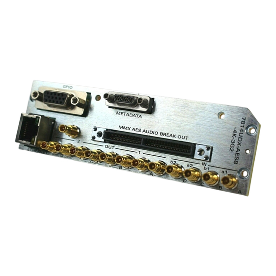
- 4 Figure 2-1: 7814Xxx-XX-2 Rear Plate Layout & 7814Xxx-Aes8-XX-2 Rear Plate Layout
- 5 Input/Output Connections
- Download this manual
7814 Series Dual HDTV Up/Down/Cross Converters
© Copyright 2014-2018
EVERTZ MICROSYSTEMS LTD.
5292 John Lucas Drive
Burlington, Ontario
Canada L7L 5Z9
Phone:
+1 905-335-3700
Sales:
sales@evertz.com
Tech Support: service@evertz.com
Web Page:
http://www.evertz.com
Version 1.1.3, October 2018
The material contained in this manual consists of information that is the property of Evertz Microsystems and is intended solely for the use of
purchasers of the 7814 series product. Evertz Microsystems expressly prohibits the use of this manual for any purpose other than the operation
of the 7814 series product. Due to ongoing research and development, features and specifications in this manual are subject to change without
notice.
All rights reserved. No part of this publication may be reproduced without the express written permission of Evertz Microsystems Ltd. Copies of
this manual can be ordered from your Evertz dealer or from Evertz Microsystems.
7800/7700 MultiFrame Manual
User Manual
Fax: +1 905-335-3573
Fax: +1 905-335-7571
Advertisement
Table of Contents


Need help?
Do you have a question about the MultiFrame 7814 Series and is the answer not in the manual?
Questions and answers