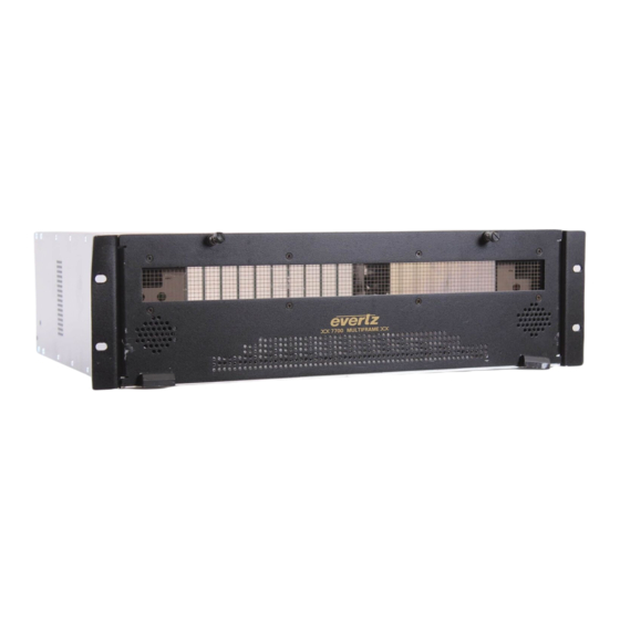
evertz MultiFrame 7700 Manual
Dual wideband rf fiber transmitter
Hide thumbs
Also See for MultiFrame 7700:
- Manual (58 pages) ,
- User manual (32 pages) ,
- Manual (18 pages)
Table of Contents
Advertisement
Quick Links
1.
OVERVIEW ....................................................................................................................................... 1
2.
INSTALLATION ................................................................................................................................. 3
2.1. 7807LT-2 CONNECTIONS ....................................................................................................... 4
2.2. CARE AND HANDLING OF OPTICAL FIBER .......................................................................... 5
2.2.1. Safety ............................................................................................................................ 5
2.2.1.1. 7807LT-2 1310nm FP and CWDM Versions .................................................... 5
2.2.2. Assembly ....................................................................................................................... 5
2.2.3. Labeling ......................................................................................................................... 5
2.2.4. Handling and Connecting Fibers .................................................................................... 6
3.
SPECIFICATIONS ............................................................................................................................. 7
3.1. RF INPUT.................................................................................................................................. 7
3.2. RF MONITOR OUTPUT ............................................................................................................ 7
3.3. OPTICAL OUTPUT ................................................................................................................... 7
3.4. GENERAL PURPOSE OUTPUTS ............................................................................................. 7
3.5. ELECTRICAL ............................................................................................................................ 7
3.6. PHYSICAL (NUMBER OF SLOTS) ........................................................................................... 8
3.7. COMPLIANCE .......................................................................................................................... 8
3.8. RF SYSTEM PERFORMANCE 7807LT-2+7807LR-2 PAIR ...................................................... 8
4.
STATUS INDICATORS ...................................................................................................................... 9
5.
JUMER POSITIONS ........................................................................................................................ 12
5.1. 7807LT-2 JUMPERS AND LEDS ............................................................................................ 12
FRAME STATUS .................................................................................................................... 12
5.3. CONFIGURING THE MODULE FOR FIRMWARE UPGRADES ............................................. 13
5.4. FACTORY AND BDM JUMPERS ........................................................................................... 13
5.5. GPO JUMPERS ...................................................................................................................... 13
7807LT-2 Dual Wideband RF Fiber Transmitter
TABLE OF CONTENTS
Revision 1.2
7700/7800 MultiFrame Manual
Advertisement
Table of Contents

Related Manuals for evertz MultiFrame 7700


Summary of Contents for evertz MultiFrame 7700
-
Page 1: Table Of Contents
7700/7800 MultiFrame Manual 7807LT-2 Dual Wideband RF Fiber Transmitter TABLE OF CONTENTS OVERVIEW ............................1 INSTALLATION ..........................3 2.1. 7807LT-2 CONNECTIONS ....................... 4 2.2. CARE AND HANDLING OF OPTICAL FIBER ................5 2.2.1. Safety ..........................5 2.2.1.1. 7807LT-2 1310nm FP and CWDM Versions ............ 5 2.2.2. - Page 2 7700/7800 MultiFrame Manual 7807LT-2 Dual Wideband RF Fiber Transmitter DOT-MATRIX DISPLAY ........................14 6.1. 7807LT-2 CONTROLLED PARAMETERS ................18 6.1.1. Adjusting the RF Input Power Alarm ................18 6.1.2. Selecting the Input Gain Mode ..................18 6.1.3. Enabling/Disabling Squelch Mode ................19 6.1.4.
- Page 3 7700/7800 MultiFrame Manual 7807LT-2 Dual Wideband RF Fiber Transmitter Figures Figure 1-1: 7807LT-2 Block Diagram ....................2 Figure 2-1: 7807LT-2 Module ......................3 Figure 5-1: Location of 7807LT-2 Jumpers and LEDs ..............12 Figure 6-1: Card Edge Menu Structure .................... 17 Tables Table 4-1: LED Status Indicators .....................
- Page 4 7700/7800 MultiFrame Manual 7807LT-2 Dual Wideband RF Fiber Transmitter This page left intentionally blank Revision 1.2...
- Page 5 June 2014 Information contained in this manual is believed to be accurate and reliable. However, Evertz assumes no responsibility for the use thereof nor for the rights of third parties, which may be affected in any way by the use thereof. Any representations in this document concerning performance of Evertz products are for informational use only and are not warranties of future performance, either expressed or implied.
- Page 6 7700/7800 MultiFrame Manual 7807LT-2 Dual Wideband RF Fiber Transmitter CAUTION If the LNB POWER LED is on, there will be DC voltage for LNB power at the associated RF INPUT connector. This can damage some test equipment. The user can turn off the LNB power under using the card-edge control system under the LNBV menu item.
-
Page 7: Overview
7700/7800 MultiFrame Manual 7807LT-2 Dual Wideband RF Fiber Transmitter OVERVIEW The 7807LT-2 is a dual fiber optic transmitter for RF signals in the extended L-Band frequency range and below, for frequencies such as over-the-air DTV. It accepts two RF inputs from coaxial cable and provides two outputs for optical transmission. -
Page 8: Figure 1-1: 7807Lt-2 Block Diagram
7700/7800 MultiFrame Manual 7807LT-2 Dual Wideband RF Fiber Transmitter Fiber Monitor Output 1 Out 1 Optical Transmitter LNB Power Current Monitor (7807LT-2 “Non -W” version) Supply 22 kHz Tone RF In/LNB Fiber Power 1 Output Local Toggle Switch/ Dot Matrix Display Control Coupler pushbutton... -
Page 9: Installation
7700/7800 MultiFrame Manual 7807LT-2 Dual Wideband RF Fiber Transmitter INSTALLATION The 7807LT-2 comes with a companion rear plate appropriate for a 1RU, 3RU or standalone enclosure as specified at the time of order. SC/UPC, SC/APC, ST/UPC, FC/UPC or FC/APC optical connectors are available and the type specified at the time of order will be installed. -
Page 10: 7807Lt-2 Connections
SC/UPC, SC/APC, FC/UPC, FC/APC or ST/UPC female connectors with the optical outputs from the 7807LT-2. These connectors should be connected to the FIBER IN connectors of an appropriate Evertz companion receiver model at the destination end with suitable fiber optic cables. The 7807LT-2 may transmit 1310nm, 1550nm or CWDM wavelengths as indicated by the part number on the card ejector. -
Page 11: Care And Handling Of Optical Fiber
Triangular band: black Symbol: black 2.2.2. Assembly Assembly or repair of the laser sub-module is to be done only at the Evertz facility and performed only by Evertz technical personnel. 2.2.3. Labeling Certification and Identification labels are combined into one label. As there is inadequate space on the product to place the label, it is reproduced here in the manuals. -
Page 12: Handling And Connecting Fibers
The transmission characteristics of the fiber are dependent on the shape of the optical core and therefore care must be taken to prevent fiber damage due to heavy objects or abrupt fiber bending. Evertz recommends that the user maintain a minimum bending radius of 5 cm to avoid fiber-bending loss that will decrease the maximum attainable distance of the fiber cable. -
Page 13: Specifications
7700/7800 MultiFrame Manual 7807LT-2 Dual Wideband RF Fiber Transmitter SPECIFICATIONS 3.1. RF INPUT Number of Inputs: Connector: BNC per IEC 61169-8 Annex A (F-Type Optional) Input Impedance: 75Ω (50Ω Optional) Return Loss: >14dB to 2100MHz >10dB from 2100MHz to 2800MHz Frequency Range: 1310nm FP laser: 850MHz-2800MHz... -
Page 14: Physical (Number Of Slots)
7700/7800 MultiFrame Manual 7807LT-2 Dual Wideband RF Fiber Transmitter 3.6. PHYSICAL (NUMBER OF SLOTS) 7800FR: 7701FR: S7701FR: 3.7. COMPLIANCE Laser Safety: Class 1 laser product for 1310nm FP and CWDM versions Complies with 24 CFR 1040.10 and 1040.11 IEC 60825-1 EMI/RFI: Complies with FCC regulations for Class A devices. -
Page 15: Status Indicators
7700/7800 MultiFrame Manual 7807LT-2 Dual Wideband RF Fiber Transmitter STATUS INDICATORS The 7807LT-2 has fourteen LED status indicators on the front card edge to show operational status of the card at a glance. See Figure 5-1 for LED locations. Two large LEDs on the front of the board indicate the general health of the module: LOCAL FAULT: This red LED will be ON during the absence of a valid RF input signal on Channel 1 or 2 (too low, too high or equal to corresponding upper and lower... - Page 16 7700/7800 MultiFrame Manual 7807LT-2 Dual Wideband RF Fiber Transmitter LED # Colour Function RF Input Power on Channel 1 or 2 is greater than or equal to the corresponding upper threshold setting, or AGC Channel 1 or 2 is ON but unable to maintain output power setting, or RF Input Power on Channel 1 or 2 LOCAL / is less than or equal to the lower threshold setting, or LNB is Short (fault) on...
-
Page 17: Table 4-1: Led Status Indicators
7700/7800 MultiFrame Manual 7807LT-2 Dual Wideband RF Fiber Transmitter LNB OFF on CH1 LNB Short (fault) on CH1 BLINKS LNB OK (no short) LNBV SET TO 13V on CH1 Power GREEN Status GREEN LNB OK (no short) LNBV SET TO 18V on CH1 LNB OFF on CH1 Table 4-1: LED Status Indicators Page - 11... -
Page 18: Jumer Positions
7700/7800 MultiFrame Manual 7807LT-2 Dual Wideband RF Fiber Transmitter JUMPER POSITIONS 5.1. 7807LT-2 JUMPERS AND LEDS Toggle Switch LOCAL FAULT GPO1 / MODULE OK RF High CH1 RF High CH2 GPO2 RF OK CH1 RF OK CH2 RF Low CH1 RF Low CH2 AGC Status CH1 AGC Status CH2... -
Page 19: Configuring The Module For Firmware Upgrades
® 5.4. FACTORY AND BDM JUMPERS When shipped from the Evertz facility, the FACTORY and BDM jumpers will not be installed. These jumpers should not be installed for any reason. If jumpers are on these positions they should be removed. -
Page 20: Dot-Matrix Display
7700/7800 MultiFrame Manual 7807LT-2 Dual Wideband RF Fiber Transmitter DOT-MATRIX DISPLAY Signal and status monitoring and control of the card’s parameters are provided via the four-digit alphanumeric display located on the card edge. The card-edge toggle-switch (see Figure 5-1) is used to navigate through the display menus and the push button is used to select options. - Page 21 7700/7800 MultiFrame Manual 7807LT-2 Dual Wideband RF Fiber Transmitter Level 1 Level 2 Level 3 Level 4 Level 5 BACK BACK 0 to -60 dBm. Default -60 dBm 0 to -60 dBm. RFTH Default -60 dBm 0 to -60 dBm. UPPR Default 0 dBm 0 to -60 dBm.
- Page 22 7700/7800 MultiFrame Manual 7807LT-2 Dual Wideband RF Fiber Transmitter 0 to 500mA default = 0 0 to 500mA LNTH default = 0 (visible only for - 0 to 500mA LNB versions) default = 500 0 to 500mA UPPR default = 500 CHAN CTRL Fault...
-
Page 23: Figure 6-1: Card Edge Menu Structure
7700/7800 MultiFrame Manual 7807LT-2 Dual Wideband RF Fiber Transmitter LNBV (visible only for - LNB versions) 22KT (visible only for - LNB versions) STAT (continued) 0 to 500mA LNBC (visible only for - LNB versions) 0 to 500mA 0 to 500mA UPPR 0 to 500mA LNTH... -
Page 24: 7807Lt-2 Controlled Parameters
7700/7800 MultiFrame Manual 7807LT-2 Dual Wideband RF Fiber Transmitter 6.1. 7807LT-2 CONTROLLED PARAMETERS To change the 7807LT-2 parameters, select the CTRL menu item in menu level 1. The toggle switch may then be used to select the parameter to change as described below. 6.1.1. -
Page 25: Enabling/Disabling Squelch Mode
7700/7800 MultiFrame Manual 7807LT-2 Dual Wideband RF Fiber Transmitter 6.1.3. Enabling/Disabling Squelch Mode Squelch mode will turn off the laser output if the RF input drops below the squelch threshold setting (see section 6.1.4). This feature is useful for triggering downstream automatic main/standby protection switches, and for other such applications. -
Page 26: Adjusting The Agc Target Level
7700/7800 MultiFrame Manual 7807LT-2 Dual Wideband RF Fiber Transmitter 6.1.6. Adjusting the AGC Target Level The target output level to be maintained by the 7807LT-2 when AGC mode is user adjustable. Adjustment of this parameter allows optimal laser depth of modulation and CNR performance to be achieved. -
Page 27: Configuring The 22Khz Tone
7700/7800 MultiFrame Manual 7807LT-2 Dual Wideband RF Fiber Transmitter 6.1.9. Configuring the 22KHz Tone A 22KHz tone may be combined with the LNB voltage for universal LNB local oscillator control. The 22KHz tone can be enabled or disabled via the 22KT selection menu. To select the 22KHz tone, select the CTRL menu item in the first menu level, then use the toggle switch to display the 22KT option and press the pushbutton to select it. -
Page 28: Setting The Display Orientation
7700/7800 MultiFrame Manual 7807LT-2 Dual Wideband RF Fiber Transmitter 6.1.12. Setting the Display Orientation The DISP option allows the user to set a horizontal or vertical orientation for the card edge display. To set the display orientation, select the CTRL menu item in the first menu level, then use the toggle switch to display the DISP option and use the pushbutton to select it. -
Page 29: Displaying The Laser Status
7700/7800 MultiFrame Manual 7807LT-2 Dual Wideband RF Fiber Transmitter STAT Squelch mode enabled. Squelch mode disabled. CH1/CH2 6.1.17. Displaying the Laser Status To display the laser status, select the STAT menu item in the first menu level, then use the toggle switch to display the LASR option and press the pushbutton to select it. -
Page 30: Displaying The Lnb Current Threshold Level
7700/7800 MultiFrame Manual 7807LT-2 Dual Wideband RF Fiber Transmitter STAT Indicates the LNB current. Visible for -LNB versions only. LNBC CH1/CH2 LNB current range. 0 to 500mA 0 to 500mA 6.1.21. Displaying the LNB Current Threshold Level To display the LNB Current threshold, select the STAT menu item in the first menu level, then use the toggle switch to display the LNTH option and press the pushbutton to select it. -
Page 31: Vistalink ® Remote Monitoring/Control
WHAT IS VISTALINK ® VistaLINK is Evertz’ remote monitoring and configuration platform which operates over an Ethernet ® network using Simple Network Management Protocol (SNMP). SNMP is a standard computer network protocol that enables different devices sharing the same network to communicate with each other. -
Page 32: Vistalink Monitored Parameters
7700/7800 MultiFrame Manual 7807LT-2 Dual Wideband RF Fiber Transmitter 7.2. VISTALINK MONITORED PARAMETERS ® The following parameters can be remotely monitored through the VistaLINK interface. ® Parameter Description RF Input Power Threshold A range of values indicating the lower/upper RF threshold levels. RF Input Power RF power level at the inputs. -
Page 33: Vistalink ® Traps
7700/7800 MultiFrame Manual 7807LT-2 Dual Wideband RF Fiber Transmitter 7.4. VISTALINK TRAPS ® The following traps can be controlled through the VistaLINK interface. Each trap will indicate a fault ® condition when its value is True. Trap Description RF Input Power High Input power is above the threshold. - Page 34 7700/7800 MultiFrame Manual 7807LT-2 Dual Wideband RF Fiber Transmitter This page left intentionally blank Page - 28 Revision 1.2...
Need help?
Do you have a question about the MultiFrame 7700 and is the answer not in the manual?
Questions and answers