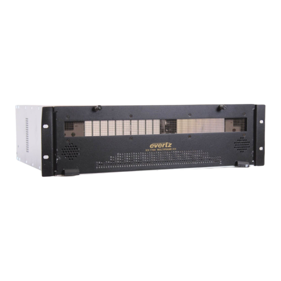
evertz MultiFrame 7700 Manual
Multi-signal hd/sd, aes, and control fiber receiver
Hide thumbs
Also See for MultiFrame 7700:
- Manual (58 pages) ,
- User manual (32 pages) ,
- Manual (26 pages)
Table of Contents
Advertisement
Quick Links
1.
OVERVIEW.......................................................................................................................................... 1
2.
INSTALLATION................................................................................................................................... 3
2.1.1. Electrical Signal Connections.......................................................................................... 4
2.1.2. Optical Signal Connections ............................................................................................. 5
2.1.2.1. Single Fiber Version ......................................................................................... 5
2.1.2.2. Dual Fiber Versions .......................................................................................... 6
2.2. CARE AND HANDLING OF OPTICAL FIBER........................................................................... 6
2.2.1. Safety .............................................................................................................................. 6
2.2.2. Assembly......................................................................................................................... 7
2.2.3. Labeling........................................................................................................................... 7
2.2.4. Handling and Connecting Fibers ..................................................................................... 7
3.
SPECIFICATIONS............................................................................................................................... 8
3.1. SERIAL DIGITAL VIDEO OUTPUT............................................................................................ 8
3.2. AES AUDIO OUTPUTS .............................................................................................................. 8
3.3. SERIAL DATA ............................................................................................................................ 8
3.4. GENERAL PURPOSE INPUTS.................................................................................................. 9
3.5. GENERAL PURPOSE OUTPUTS.............................................................................................. 9
3.6. OPTICAL INPUTS/OUTPUTS .................................................................................................... 9
3.7. ELECTRICAL ............................................................................................................................. 9
3.8. PHYSICAL .................................................................................................................................. 9
4.
STATUS INDICATORS AND DISPLAYS ......................................................................................... 10
4.1. STATUS INDICATOR LEDS .................................................................................................... 10
4.2. DOT MATRIX DISPLAY ........................................................................................................... 11
4.2.1. Displaying Warning Status Indications .......................................................................... 13
4.2.2. Displaying the Standard of Input Video ......................................................................... 13
4.2.3. Displaying the Embedded Audio Status of Input Video................................................. 14
4.2.4. Displaying the GPI Status ............................................................................................. 14
4.2.5. Displaying the GPO Status............................................................................................ 14
4.2.6. Displaying the Received Optical Power ........................................................................ 15
4.2.7. Displaying the Firmware Version................................................................................... 15
4.2.8. Selecting the Laser Output Mode on LOS..................................................................... 15
4.2.9. Selecting the Video Output Mode on LOS .................................................................... 16
4.2.10. Selecting Output Video HANC Cleaning ....................................................................... 16
4.2.11. Selecting Balanced or Unbalanced Audio ..................................................................... 16
7707MRA-HD Multi-Signal HD/SD, AES, and Control Fiber Receiver
TABLE OF CONTENTS
Revision 1.4
7700 MultiFrame Manual
Advertisement
Table of Contents

Related Manuals for evertz MultiFrame 7700


Summary of Contents for evertz MultiFrame 7700
-
Page 1: Table Of Contents
7700 MultiFrame Manual 7707MRA-HD Multi-Signal HD/SD, AES, and Control Fiber Receiver TABLE OF CONTENTS OVERVIEW............................1 INSTALLATION........................... 3 2.1.1. Electrical Signal Connections..................4 2.1.2. Optical Signal Connections ..................... 5 2.1.2.1. Single Fiber Version ..................5 2.1.2.2. Dual Fiber Versions ..................6 2.2. - Page 2 7700 MultiFrame Manual 7707MRA-HD Multi-Signal HD/SD, AES, and Control Fiber Receiver 4.2.12. Selecting AES Pop-Reduction and Generation on LOS..........17 4.2.13. Selecting the Serial Data Type..................17 4.2.14. Selecting the Serial Data Rate ..................18 4.2.15. Selecting the Serial Data Fail Safe Bias................ 18 4.2.16.
- Page 3 Sept 2010 Information contained in this manual is believed to be accurate and reliable. However, Evertz assumes no responsibility for the use thereof nor for the rights of third parties, which may be affected in any way by the use thereof. Any representations in this document concerning performance of Evertz products are for informational use only and are not warranties of future performance, either expressed or implied.
- Page 4 7700 MultiFrame Manual 7707MRA-HD Multi-Signal HD/SD, AES, and Control Fiber Receiver WARNING Never look directly into an optical fiber. Non-reversible damage to the eye can occur in a matter of milliseconds. Revision 1.4...
-
Page 5: Overview
7700 MultiFrame Manual 7707MRA-HD Multi-Signal HD/SD, AES, and Control Fiber Receiver OVERVIEW The 7707MRA-HD is a fiber optic receiver for one HD or SD digital video signal, accompanied by four AES audio signals, serial data, two GPI and two GPO signals. Audio and control signals are de-embedded from the HD, SD, or SDTi video signal that is applied to the optical input. -
Page 6: Figure 1-1: 7707Mra-Hd Block Diagram
7700 MultiFrame Manual 7707MRA-HD Multi-Signal HD/SD, AES, and Control Fiber Receiver VistaLINK ® Interface Control/ Local Indication Local Video Encoder Video Control Indication HD/SD Serial SMPTE 292M Outputs SMPTE 259M-C SMPTE 305M Video -F2 Version Fiber 4 AES Audio Input Optical Data Outputs... -
Page 7: Installation
7700 MultiFrame Manual 7707MRA-HD Multi-Signal HD/SD, AES, and Control Fiber Receiver INSTALLATION Each 7707MRA-HD module comes with a companion rear plate that has two BNC connectors, a multi-pin removable terminal block, and an SC/PC (shown), ST/PC or FC/PC optical connector. For information on mounting the rear plate and inserting the module into the frame see section 3 of the 7700FR chapter. -
Page 8: Electrical Signal Connections
7700 MultiFrame Manual 7707MRA-HD Multi-Signal HD/SD, AES, and Control Fiber Receiver Figure 2-2: 7707MRA-HD Rear Plates & Pin Out (1RU version) 2.1.1. Electrical Signal Connections Reclocked, level-restored, loop-back output BNC connectors for serial digital video HD/SD OUTPUT: signals compatible with HD-SDI (SMPTE 292M), SD-SDI (SMPTE 259M-C), DVB- ASI and SDTi (SMPTE 305.2M) standards. -
Page 9: Optical Signal Connections
7700 MultiFrame Manual 7707MRA-HD Multi-Signal HD/SD, AES, and Control Fiber Receiver SERIAL I/O: Bi-directional serial data connections of the removable terminal block. The 7707MRA-HD accommodates one channel of RS-422, RS-232, or RS-485 serial data. Data input connections are labeled DI, while data output connections are labeled DO. The card must be configured for use with RS-422, RS-232, or RS-485, as described in section 4.2.9. -
Page 10: Dual Fiber Versions
7700 MultiFrame Manual 7707MRA-HD Multi-Signal HD/SD, AES, and Control Fiber Receiver The optical output can be configured to operate in continuous or discontinuous mode as described in section 4.2.7. If discontinuous mode is selected, while the optical input to the 7707MRA-HD is invalid (LINK…LOS condition, section 4.2.1) then this optical output will be disabled. -
Page 11: Assembly
7700 MultiFrame Manual 7707MRA-HD Multi-Signal HD/SD, AES, and Control Fiber Receiver 2.2.2. Assembly Assembly or repair of the laser sub-module is done only at Evertz facility and performed only by qualified Evertz technical personnel. 2.2.3. Labeling Certification and Identification labels are combined into one label. As there is not enough room on the product to place the label it is reproduced here in the manuals. -
Page 12: Specifications
7700 MultiFrame Manual 7707MRA-HD Multi-Signal HD/SD, AES, and Control Fiber Receiver SPECIFICATIONS 3.1. SERIAL DIGITAL VIDEO OUTPUT 2 (regenerated) Number of Outputs: SMPTE 292M (HD-SDI), SMPTE 259M-C (SD-SDI), SMPTE305.2M Standards: (SDTi), DVB-ASI (audio outputs, serial data and GPIO will not be present) 1 BNC per IEC 61169-8 Annex A Connector:... -
Page 13: General Purpose Inputs
7700 MultiFrame Manual 7707MRA-HD Multi-Signal HD/SD, AES, and Control Fiber Receiver 3.4. GENERAL PURPOSE INPUTS Number of Signals: Multi-pin Removable Terminal Block Connector at Breakout: Opto-isolated, Active low Type: Input Voltage: -20V to +10V Safe Voltage Range: +3.5V Off Condition (min): +2.5V (active low) On Condition (max): Input Current (min):... -
Page 14: Status Indicators And Displays
7700 MultiFrame Manual 7707MRA-HD Multi-Signal HD/SD, AES, and Control Fiber Receiver STATUS INDICATORS AND DISPLAYS The 7707MRA-HD has 9 LED Status indicators and a 4 digit alphanumeric display on the front card edge to show operational status of the card at a glance. The card edge pushbutton is used to select various options on the alphanumeric display. -
Page 15: Dot Matrix Display
7700 MultiFrame Manual 7707MRA-HD Multi-Signal HD/SD, AES, and Control Fiber Receiver There are seven small LEDs on the back of the card-edge that indicate signal presence. Some of these LEDs are Bi-colour, and able to illuminate as red or green. The functions of these LEDs are as follows: This LED indicates the status of the Fiber Input. -
Page 16: Figure 4-2: Card Edge Menu Structure
7700 MultiFrame Manual 7707MRA-HD Multi-Signal HD/SD, AES, and Control Fiber Receiver P u s h b u t t o n M e n u L e v e l 1 M e n u L e v e l 2 M e n u L e v e l 3 M e n u L e v e l 4 M e n u L e v e l 5... -
Page 17: Displaying Warning Status Indications
7700 MultiFrame Manual 7707MRA-HD Multi-Signal HD/SD, AES, and Control Fiber Receiver 4.2.1. Displaying Warning Status Indications Upon entering menu level 1 on power up, or following a configuration selection, the default display selection will indicate the warning status of the 7707MRA-HD. This warning status indication can also be entered while already in menu level 1, by using the toggle switch. -
Page 18: Displaying The Embedded Audio Status Of Input Video
7700 MultiFrame Manual 7707MRA-HD Multi-Signal HD/SD, AES, and Control Fiber Receiver 4.2.3. Displaying the Embedded Audio Status of Input Video The 7707MRA-HD allows the user to monitor the status of input video embedded audio groups. This allows for easy identification of active groups. To view the current status of input video embedded audio groups, select the STAT (Status) menu item in menu level 1, followed by the FIN (Fiber Input) and GRP1, GRP2, GRP3 or GRP4 (Audio Groups 1 through 4) menu items. -
Page 19: Displaying The Received Optical Power
7700 MultiFrame Manual 7707MRA-HD Multi-Signal HD/SD, AES, and Control Fiber Receiver 4.2.6. Displaying the Received Optical Power The 7707MRA-HD is equipped with an on-board optical power meter and can report the power to the card edge display in units of dBm. To indicate the input strength of the received signal, select the STAT (Status) menu item in menu level 1 followed by the PWR (Optical Power) menu item. -
Page 20: Selecting The Video Output Mode On Los
7700 MultiFrame Manual 7707MRA-HD Multi-Signal HD/SD, AES, and Control Fiber Receiver 4.2.9. Selecting the Video Output Mode on LOS In order to maintain audio transport during input video loss, a generated output video signal may be enabled during this condition. A black or gray active picture may be selected. Alternately, to force a downstream signal loss during this condition, output generation may be disabled. -
Page 21: Selecting Aes Pop-Reduction And Generation On Los
7700 MultiFrame Manual 7707MRA-HD Multi-Signal HD/SD, AES, and Control Fiber Receiver 4.2.12. Selecting AES Pop-Reduction and Generation on LOS Three AES output generation modes are available during audio loss. With AES output generation disabled (OFF), the output signal is muted (i.e., no electrical transitions). With AES output generation set enabled (ON), the output signal is AES silence. -
Page 22: Selecting The Serial Data Rate
7700 MultiFrame Manual 7707MRA-HD Multi-Signal HD/SD, AES, and Control Fiber Receiver 4.2.14. Selecting the Serial Data Rate A serial data rate selection is only required for RS-485 data. To select the serial data rate, select the CTRL (Control) menu item in menu level 1, followed by the SER (Serial Data), followed by the RATE (Baud Rate). Configures card to transmit at 300Kb/s CTRL Configures card to transmit at 600 Kb/s... -
Page 23: Selecting Audio De-Embedding Groups
7700 MultiFrame Manual 7707MRA-HD Multi-Signal HD/SD, AES, and Control Fiber Receiver 4.2.16. Selecting Audio De-embedding Groups This user menu item provides configuration of the de-embedded audio groups. To select the audio de- embedding groups select the CTRL (Control) menu item in menu level 1, followed by the EMBD (De- embedding) and then A1+2 (AES 1 and AES 2) or A3+4 (AES 3 and AES 4) menu items. -
Page 24: Selecting Gpio De-Embedding Parameters
7700 MultiFrame Manual 7707MRA-HD Multi-Signal HD/SD, AES, and Control Fiber Receiver 4.2.18. Selecting GPIO De-embedding Parameters The 7707MRA-HD de-embeds GPIO from vertical ancillary (VANC) data space of the optical input video. The VANC de-embedding parameters of the 7707MRA-HD should be configured to match embedding parameters of the companion 7707MTA-HD-W. -
Page 25: Selecting Fiber Input Error Detection
7700 MultiFrame Manual 7707MRA-HD Multi-Signal HD/SD, AES, and Control Fiber Receiver 4.2.19. Selecting Fiber Input Error Detection The 7707MRA-HD is capable of detecting CRC or EDH errors in optical input video. To turn error detection on or off select the CTRL (Control) menu item in menu level 1 followed by the EDET (Error Detection) menu items, and then select the FIN (Fiber Input) menu item. -
Page 26: Selecting The Factory Reset Configuration
7700 MultiFrame Manual 7707MRA-HD Multi-Signal HD/SD, AES, and Control Fiber Receiver 4.2.22. Selecting the Factory Reset Configuration It is convenient to have a quick method of returning all configuration settings to a default state. The 7707MRA-HD provides a factory reset for this purpose. All values that are user configurable will be returned to a known state, as indicated below. -
Page 27: Jumpers And Controls
7700 MultiFrame Manual 7707MRA-HD Multi-Signal HD/SD, AES, and Control Fiber Receiver JUMPERS AND CONTROLS Several jumpers, located at the front of the module, are used to preset various operating modes. Figure 4-1 shows the locations of the jumpers. 5.1. SELECTING WHETHER LOCAL FAULTS WILL BE MONITORED BY THE GLOBAL FRAME STATUS The FRAME STATUS jumper determines whether local faults (as shown by the Local Fault indicator) will be connected to the 7700FR frame's global status bus. - Page 28 7700 MultiFrame Manual 7707MRA-HD Multi-Signal HD/SD, AES, and Control Fiber Receiver This page left intentionally blank Revision 1.4 Page-24...
Need help?
Do you have a question about the MultiFrame 7700 and is the answer not in the manual?
Questions and answers