Sign In
Upload
Manuals
Brands
Ducati Manuals
Motorcycle
ST3 2004
Ducati ST3 2004 Manuals
Manuals and User Guides for Ducati ST3 2004. We have
1
Ducati ST3 2004 manual available for free PDF download: Workshop Manual
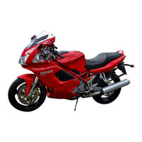
Ducati ST3 2004 Workshop Manual (631 pages)
Brand:
Ducati
| Category:
Motorcycle
| Size: 36 MB
Table of Contents
General Summary
2
Description
14
Manual Layout
17
Symbols
18
Abbreviations
18
Text References
18
Product Specifications
21
General Safety Rules
23
Carbon Oxide
23
Fuel
23
Hot Component Parts
23
Used Engine Oil
24
Brake Lining Debris
24
Brake Fluid
24
Coolant
24
Model-Specific Information
28
Identification Data
29
Identification Data for ST3
30
Data Punched on Frame
30
Data Punched on Engine
31
Technical Specification
32
Overall Dimensions (MM)
48
Fuels and Lubricants
49
Engine Oil
49
Oil Viscosity
49
Service Tools
73
Engine Special Tools
73
Frame Special Tools
78
Use and Maintenance Operations
80
Preliminary Checks
82
Running-In Precautions
82
Max. Rotation Speed
82
Max. Rotation Speed up to 1000 Km
82
Pre-Ride Checks
83
Fuel Level in the Tank
83
Engine Oil Level
83
Brake and Clutch Fluid
83
Key-Operated Locks
84
Stand
84
Starting the Engine
85
Cold Ambient Temperature
85
High Ambient Temperature
86
Routine Maintenance Table
89
Maintenance Operations
91
Cancelling the "Service" Indicator on the Instrument Panel
91
Checking the Engine Oil Level
92
Changing the Engine Oil and Filter Cartridge
93
Checking Valve Clearances
95
Opening Rocker Arm
95
Adjusting Valve Clearances
96
Closing Rocker Arm
96
Checking the Coolant Level
97
Changing the Coolant
98
Changing the Fuel Filter
100
Changing the Air Filter
101
Changing the Brake Fluid
102
Changing the Fluid in the Front Brake Circuit
102
Changing the Fluid in the Rear Brake Circuit
103
Draining the Brake Circuits
104
Filling the Brake Circuits
105
Changing the Clutch Fluid
107
Draining the Clutch Circuit
108
Refilling the Clutch Circuit
109
Steering Angle Adjustment
111
Adjusting the Front Brake and Clutch Levers
112
Adjusting Chain Tension
113
Checking Brake Pad Wear. Changing Brake Pads
114
Checking Front Brake Wear
114
Changing Rear Brake Pads
116
Adjusting the Throttle and Choke Cables
117
Adjusting the Position of the Gear Change and Rear Brake Pedals
119
Adjusting the Front Fork
120
Adjusting the Rear Shock Absorber
121
Adjusting Setup
121
Diagnostic Instruments
122
Description of the Diagnostic Tester
123
Connecting the Tester to the Motorcycle
124
Parts Delivered with the Diagnostic Tester
124
The Mathesis Diagnostic Tester
125
Checking and Adjusting Cam Belt Tension
126
Belt Reading
128
Adjusting the Throttle Body
130
Positioning the Throttle Sensor
131
Adjusting the Throttle Position Sensor
131
Adjusting the Idling Mixture
132
Adjusting the Throttle Set Screw (Vertical Cylinder)
132
Balancing the Air Flows
132
Adjusting the CO Rate
133
Adjusting the Choke Control
134
Checking Engine Oil Pressure
135
Hot Engine
136
Checking Cylinder Compression
137
Checking Fuel Pressure
139
Fairing
140
Headlight Fairing - Rear-View Mirrors
142
Removing the Rear View Mirrors and Dash Panels
143
Disassembling the Headlight Fairing
145
Refitting the Headlight Fairing
147
Refitting the Rear View Mirrors and Dash Panels
149
Removing Lower Side Fairings
153
Reassembling Lower Side Fairings
154
Removing the Complete Fairings
155
Removing the Front Shield
159
Reassembling the Front Shield
159
Tail Guard
160
Removing the Seat
161
Removing the Side Panels
162
Removing the Tool Compartments - Rear Splashguard
163
Reassembling the Tool Compartments - Rear Splashguard
163
Reassembling the Side Panels
164
Refitting the Seat
165
Removing the Front Mudguard
166
Reassembling the Front Mudguard
166
Controls - Devices
168
Throttle - Choke Control
170
Disassembling the Throttle Control
172
Reassembling the Throttle Control
173
Throttle Cable Routing
174
Removing the Choke Control
175
Refitting the Choke Control
176
Choke Cable Routing
178
Clutch Hydraulic Control
179
Removing the Clutch Cylinder Assembly
180
Fitting the Clutch Cylinder Assembly
180
Removing the Clutch Slave Cylinder Assembly
181
Refitting the Clutch Slave Cylinder Assembly
182
Clutch Cable Routing
183
Front Brake Control
184
Removing the Front Brake Master Cylinder
185
Refitting the Front Brake Master Cylinder
186
Front Brake Hose Routing
187
Rear Brake Control
189
Removing the Rear Brake Master Cylinder
190
Refitting the Rear Brake Control
191
Disassembling the Rear Brake Control
191
Rear Brake Hose Routing
192
Gear Change Control
194
Removing the Gear Change Control
195
Disassembling the Gear Change Control
195
Refitting the Gear Change Control
195
Seat Lock
196
Removing the Seat Opening Device
197
Reassembling the Seat Opening Device
197
Wheels - Suspensions - Brakes
198
Front Wheel
200
Removing the Front Wheel
201
Overhauling the Front Wheel
202
Overhauling the Front Wheel Bearings
202
Overhauling the Front Wheel Shaft
203
Refitting the Front Wheel
204
Front Fork
205
Removing the Front Fork
206
Overhauling the Adjustable Front Fork
207
Disassembling the Adjustable Front Fork
207
Inspecting the Adjustable Front Fork
210
Reassembling the Adjustable Front Fork
211
Refitting the Front Fork
214
Front Brake
215
Braking System Maintenance
216
Removing the Front Brake System
217
Removing the Front Brake Caliper
217
Overhauling the Front Brake Components
218
Removing the Front Brake Discs
218
Refitting the Front Brake System
219
Refitting the Front Brake Discs
219
Refitting the Front Brake Caliper
219
Rear Wheel
221
Removing the Rear Wheel
222
Overhauling the Rear Wheel
223
Overhauling the Rear Brake Disc
223
Refitting the Rear Wheel
224
Rear Swingarm
225
Removing the Rear Swingarm
226
Inspecting the Swingarm Shaft
227
Checking Swingarm Axial Play
227
Refitting the Rear Swingarm
228
Rear Brake
229
Removing the Rear Brake System
230
Refitting the Rear Brake System
232
Rear Suspension
233
Rear Suspension Unit
234
Removing the Rear Shock Absorber
234
Overhauling the Rear Shock Absorber
235
Disassembling the Rear Shock Absorber
235
Reassembling the Rear Shock Absorber
235
Removing the Rear Suspension Rocker Arm
236
Overhauling the Rear Suspension Rocker Arm
237
Disassembling the Rear Suspension Rocker Arm
237
Reassembling the Rear Suspension Rocker Arm
237
Overhauling the Monoshock Linkage
238
Refitting the Rear Suspension
239
Final Drive
241
Inspecting the Final Drive
242
Removing the Front Sprocket
243
Refitting the Front Sprocket
243
Removing the Rear Sprocket
244
Refitting the Rear Sprocket
244
Washing the Chain
245
Lubricating the Chain
245
Frame
246
Handlebars
248
Removing the Handlebars
249
Removing the Grips
249
Refitting the Handlebars
250
Refitting the Grips
250
Removing the Handlebar Mountings
251
Refitting the Handlebar Mountings
252
Adjusting the Handlebar Mountings Height
252
Steering
253
Adjusting Steering Bearing Play
254
Adjusting the Steering
254
Removing the Steering Head Bearings
255
Refitting the Steering Bearings
257
Footpeg Mounts
260
Removing the Footpegs
261
Refitting Footpegs
263
Stands
265
Removing the Side Stand
266
Disassembling the Side Stand
266
Inspecting the Side Stand
266
Reassembling the Side Stand
267
Removing the Center Stand
268
Refitting the Center Stand
268
Frame Inspection
269
Frame and Related Components
270
Removing Frame and Structural Parts
270
Frame Overall Dimensions (MM)
273
Checking the Frame
274
Refitting Frame and Related Components
274
Tail Light and Number Plate Holder
275
Removing and Refitting the Rear Grab Rail
276
Removing the Tail Light
277
Refitting the Tail Light
277
Removing the Number Plate Holder
278
Refitting the Number Plate Holder
278
Fuel System / Exhaust System
280
Description of Fuel System
282
Fuel Tank
284
Raising the Fuel Tank
286
Removing the Fuel Tank
287
Changing the Fuel Filler Cap Assembly
288
Changing the Fuel Sensor
288
Refitting the Fuel Tank
289
Fuel Tank Breather and Drain Hose Routing
290
Fuel Pump
291
Removing the Fuel Pump
292
Refitting the Fuel Pump
292
Fuel Filter
293
Pressure Regulator
295
Changing the Pressure Regulator
295
Throttle Body
296
Removing the Complete Throttle Body
297
Refitting the Complete Throttle Body
298
Hose Routing
299
Air Filter
301
Removing the Filter Box
302
Refitting the Filter Box
304
Filter Box Drain Hose Routing
306
Exhaust System
307
Catalytic Converter Operating Principle
308
Removing the Exhaust System
309
Reassembling the Exhaust System
310
Canister Filter
311
Removing the Canister Filter
313
Refitting the Canister Filter
313
Canister Hose Routing
314
Ignition - Injection System
316
Description of the Fuel Injection-Ignition System
318
General Information on the Fuel Injection-Ignition System
318
Marelli Injection-Ignition System
319
Injection - Ignition System Sensor/Actuator Location Diagram
320
Fuel Circuit
322
Air Circuit
323
Operating Stages
324
Normal Running
324
Starting
324
Acceleration/Deceleration
324
System Diagram
325
Fuel Injection System Diagram
325
Injection - Ignition System Diagram Legend
327
System Components
328
Electronic Control Unit
328
Removing the Electronic Control Unit
330
Refitting the Control Unit
330
Electric Injector
332
Air Temperature Sensor
333
Air Pressure Sensor
333
Coolant Temperature Sensor
334
Removing the Coolant Temperature Sensor
334
Refitting the Coolant Temperature Sensor
334
Spark Plug
335
Coil
336
Throttle Position Sensor
337
Rpm/Timing Sensor
337
Injection Relay
338
The CAN Line
339
The Instrument Panel System
340
The LCD Display
341
Clock
341
Display Functions
343
Clock Display Functions
343
Time Display - Setting the Clock
343
Coolant Temperature Display
343
Main Display Functions
344
Speed Display
344
Routine Maintenance Display
344
Vertical Headlight Angle Adjustment
345
Electronic Injection/Ignition System Diagnostics
346
Special Settings
349
Fuel Display Function
351
Fuel Level Display
351
Auxiliary Display Functions
352
Display Function Scrolling
352
Odometer
352
Trip Counter
352
Instantaneous Fuel Consumption Display
353
Average Fuel Consumption Display
353
Fuel Consumed Display
353
Remaining Autonomy Display
354
The Fuel Reserve Warning Light
354
Instrument Panel Functions
355
Headlight Switching Logic
355
Switching the Headlights Back on
355
Automatic LCD Display and Rev Counter Backlighting and Automatic Function Indicator Brightness Control
355
Connector Pin-Out
357
Engine
358
Removing - Reassembling the Complete Engine
362
Removing the Engine
363
Disassembling the Engine
365
Reassembling the Engine
366
Lubrication System: Oil Pump
367
Lubrication System Diagram
368
Description of the Lubrication System
369
Lubrication System Operation
369
Removing the Oil Filters
370
Crankcase Vapor Breather Circuit
370
Removing the Oil Pump
371
Oil Pump Disassembly
371
Overhauling the Oil Pump
372
Reassembling the Oil Pump
372
Refitting the Oil Pump
373
Lubrication System/Oil Cooler
374
Removing the Lubrication System
375
Removing the Cylinder Head Oil Delivery Line
376
Refitting the Cylinder Head Oil Delivery Line
376
Overhauling the Oil Cooler
377
Fitting the Nipple and Oil Lines to the Oil Cooler
378
Refitting the Lubrication System
379
Oil Cooler Pipes Routing
380
Lubrication System: Oil Breather Tank
383
Removing the Oil Breather Reservoir
384
Refitting the Oil Breather Reservoir
384
Oil Breather Pipe Routing
385
Cooling System/Tank
387
Cooling System
388
Cooling System Legend
388
Circuit Total Capacity
388
Removing the Water Reservoir
389
Refitting the Water Reservoir
390
Cooling System: Water Radiator
391
Removing the Radiator
392
Replacing the Electric Fan
394
Inspecting the Coolant Radiator
394
Removing the Electric Fan
394
Refitting the Electric Fan
394
Refitting the Water Radiator
395
Removing the Cooling System Pipes and Unions
397
Refitting the Cooling System Pipes and Unions
399
Engine Cooling System Pipe Routing
401
Cooling System/Coolant Pump
402
Removing the Coolant Pump
403
Reassembling the Coolant Pump
405
Head Unit / Checks and Adjustments
409
Checking and Adjusting Valve Clearance
410
Checking and Adjusting Opening Clearance (Sa)
411
Checking and Adjusting Closing Clearance (Sc)
412
Checking Valve Lift
413
Checking Engine Timing
414
Heads/Timing System Assembly
416
Removing the Timing System Parts
417
Removing Timing Outer Covers
417
Timing System Disassembly
418
Disassembling the Mobile Tensioner
420
Removing the Camshaft Pulleys
420
Reassembling the Timing System
421
Reassembling the Timing Belt Rollers on Camshafts
421
Reassembling Timing Belt Rollers on Layshaft
423
Reassembling the Timing Belt Tensioners
424
Refitting the Timing Side Covers
428
Heads/Side Covers Assembly
429
Removing the Intake Manifolds
430
Refitting the Intake Manifolds
430
Camshafts Disassembly
431
Removing the Valve Covers
433
Refitting the Valve Covers
433
Removing the Camshafts
434
Checking Camshafts
435
Refitting the Camshaft
436
Refitting the Cam Covers
437
Head Unit: Valves - Rocker Arms
439
Removing the Complete Head
440
Removing the Head
440
Removing the Valves
441
Removing the Valve Rocker Arms
445
Head Parts Overhaul
447
Heads
447
Overhauling the Valve
448
Changing Valve Seats
449
Valve-To-Valve Seat Clearance
449
Overhauling the Valve Guide
450
Valve-To-Valve Guide Clearance
450
Changing Valve Guides
450
Overhauling the Rocker Arms
451
Reassembling the Head
452
Reassembling the Valve Rocker Arms
453
Refitting the Valves
456
Reassembling the Heads
459
Cylinders/Pistons Assembly
460
Removing Cylinder / Piston Assy
461
Overhauling the Cylinder
463
Overhauling the Piston
464
Piston-Cylinder Clearance
464
Overhauling the Gudgeon Pins
465
Overhauling the Piston Rings
465
Piston Ring-Piston Groove Clearance
465
Gudgeon Pin-Piston Clearance
466
Piston Rings-Cylinder Clearance
467
Refitting Cylinder / Piston Assy
468
Clutch Assembly / Clutch
471
Clutch Unit Description
472
Disassembling the Clutch
474
Checking and Overhauling the Components
477
Clearance between Clutch Housing and Drive Plate
477
Overhauling the Clutch Plates
477
Overhauling the Pressure Plate
477
Reassembling the Clutch
478
Clutch/Clutch Cover Assembly
481
Removing the Clutch Cover
482
Clutch Cover Disassembly
482
Reassembling the Clutch Cover
483
Fitting the Clutch Cover
484
Clutch/Primary Drive Gear Assembly
485
Disassembling the Primary Drive Gears
486
Reassembling Primary Drive Gear and Checking Meshing Clearance
488
Gearbox/Gear Selector Lever Assembly
490
Removing the Gear Selector Levers
491
Removing the Gear Stopper and Ratchet
492
Reassembling Gear Stopper and Ratchet
492
Reassembling the Gear Selector Lever
493
Gearbox/Gearbox Shafts Assembly
494
Removing the Gearbox
496
Disassembling the Gearbox Shafts
497
Secondary Shaft
497
Gearbox Primary Shaft
499
Overhauling the Gearbox
501
Overhauling the Gear Selector Forks
503
Fork Selector Drum
503
Reassembling the Gearbox Shafts
504
Reassembling the Gearbox
506
Flywheel - Generator
507
Removing the Generator Cover
509
Disassembling the Generator Cover
510
Removing the Flywheel - Generator Assembly
511
Checking the Flywheel - Generator Assembly
512
Disassembling the Flywheel - Generator Assembly
512
Reassembling the Flywheel - Generator Assembly
513
Refitting Flywheel / Generator Assembly
514
Reassembling the Generator Cover
515
Checking the Air Gap of Engine Sensor
517
Casing Unit
518
Removing Outer Components
519
Reassembling the Outer Parts
521
Removing the Timing Lay Gear
522
Reassembling the Timing Lay Gear
522
Removing the Starter Motor Driven Gear
523
Reassembling the Starter Motor Driven Gear
523
Opening the Casings
525
Overhauling the Casings
527
Main Bearings
528
Reassembling the Casings
529
Overhauling the Clutch-Side Casing
529
Overhauling the Generator-Side Casing
530
Shimming the Shafts
531
Shimming the Crankshaft
531
Shimming the Gearbox Drum
533
Practical Shimming Procedure for the Selector Drum and Gearbox Shafts
534
Checking Gearbox Position
537
Closing the Casings
539
Casing Unit: Connecting Rods
542
Removing the Connecting Rods
543
Disassembling the Connecting Rod
543
Overhauling the Connecting Rods
544
Changing the Connecting Rod Small End Bush
545
Changing the Connecting Rod Big End Bearings
546
Checking the Crankshaft
547
Checking Big End Bearings Crank Pin Clearance
548
Reassembling the Connecting Rods
549
Refitting the Connecting Rod Unit
550
Electric System
552
Wiring Diagram
554
Key to Wiring Diagram
556
Electrical System Fuse Box Legend
558
Arrangement of Wiring on Frame
558
Diagram a
561
Diagram B
562
Diagram C
563
Diagram D
564
Diagram E
565
Diagram F
566
Diagram H
567
Diagram J
568
Diagram K
569
Diagram L
570
Diagram M
571
Diagram N
572
Diagram P
573
Diagram Q
574
Diagram R
575
Diagram S
576
Diagram T
577
Diagram U
578
Charging System - Battery
579
Checking the Charging System
579
Charging Methods
579
Normal Charge
580
Charging the Battery under Critical Conditions
580
Battery
581
Safety Rules
581
Removing the Battery
581
Refitting the Battery
581
Battery Mount
582
Generator
583
Removing the Alternator
583
Refitting the Alternator
583
Rectifier - Regulator
584
Removing the Regulator
584
Refitting the Regulator
584
Regulator Fuse
585
Electric Starting
586
Electric Starting System
587
Safety Devices Function Table
588
Starter Motor
589
Starter Motor Removal
589
Reassembling the Starter Motor
590
Contactor
591
Starter Contactor Operational Check
591
Lighting Devices
592
Removing the Instrument Panel
592
Replacing Bulbs
593
Replacing Headlight Bulbs
593
Main Beam (HI) Bulb
594
Parking Light (A)
594
Refitting Bulbs
594
Replacing the Number Plate Bulb
594
Headlight Switching Relay
595
Checking Headlight Relay Functioning
595
Aligning Dipped (LO) Beam
596
Checking the Indicators and Lighting System Components
597
Left Switch
597
HORN Button
597
Turn Indicator Switch (TURN)
598
Low and High Beam (DIMMER)
598
Flasher (PASSING)
598
Right Switch
599
ENGINE STOP Button
599
STARTER Button
599
Hazard
599
STOP Switches
600
Neutral Light
600
Oil Pressure Sensor
601
Clutch Switch
601
Cooling Fan Relay
602
Checking High Beam and Electric Fan Relay Correct Operation
602
Changing Light Bulbs
603
Turn Indicators
603
Front Turn Indicators
603
Rear Turn Indicators
603
Replacing the Stop Light Bulb
604
Protection and Safety Devices
605
Checking Components
605
Checking the Ignition Key Switch
605
Side Stand Switch
605
Fuses Check
606
Immobilizer and Transformer
607
Transponder Keys
607
Immobilizer Antenna
608
Principle of Immobilizer Functioning
608
Function Indicator and Immobilizer Signals
609
Programming the Immobilizer
610
Checking that the Immobilizer System Is Correctly Programmed
612
First Signal: One Flash the Shows
612
Second Signal: a Series of Brief
612
Fourth Signal
612
Emergency Immobilizer Unlocking Procedure
613
Removing the Immobilizer Antenna
615
Refitting the Immobilizer Antenna
615
Disassembling the Red Transponder Key
615
Using a Multi-Meter to Test Electrical Systems
616
How to Measure Voltage
616
How to Measure Current
617
How to Measure Resistance and Electric Continuity
617
Protections and Precautions
618
Power Socket
619
Subject Index
620
Indice Generale
621
Advertisement
Advertisement
Related Products
DUCATI SPORT TOURING ST3
Ducati ST3 S ABS
DUCATI SPORTTOURING ST4S
DUCATI ST4S ABS
Ducati Streetfighter
Ducati Streetfighter 2010
Ducati Streetfighter 2011
Ducati ST2
Ducati STREETFIGHTER V4
Ducati STREETFIGHTER V4 2024
Ducati Categories
Motorcycle
Motorcycle Accessories
Scooter
Brush Cutter
Gate Opener
More Ducati Manuals
Login
Sign In
OR
Sign in with Facebook
Sign in with Google
Upload manual
Upload from disk
Upload from URL