Sign In
Upload
Manuals
Brands
Danfoss Manuals
Servo Drives
VLT DSD 510
Danfoss VLT DSD 510 Manuals
Manuals and User Guides for Danfoss VLT DSD 510. We have
1
Danfoss VLT DSD 510 manual available for free PDF download: Operating Manual
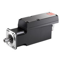
Danfoss VLT DSD 510 Operating Manual (226 pages)
Servo Drive System
Brand:
Danfoss
| Category:
Servo Drives
| Size: 16.38 MB
Table of Contents
Table of Contents
3
1 Introduction
16
Purpose of the Operating Guide
16
Additional Resources
16
Copyright
16
Approvals and Certifications
16
Firmware Updates
18
Terminology
18
2 Safety
20
Safety Symbols
20
Important Safety Warnings
20
Safety Instructions and Precautions
22
Operational Safety
22
Qualified Personnel
23
Due Diligence
23
Intended Use
23
Prohibited Application Areas
23
Forseeable Misuse
24
Service and Support
24
3 System Description
25
Overview of the ISD 510/DSD 510 System
25
Application Examples
26
VLT® Integrated Servo Drive ISD
27
Overview of the ISD 510 Servo Drive
27
Motor and Flange Sizes
27
ISD 510 Servo Drive Types
27
Motor Components
28
Shaft
28
Brake (Optional)
29
Cooling
29
Thermal Protection
29
Built-In Feedback Devices
29
Drive Components
29
Connectors on the ISD 510 Servo Drives
29
VLT® Decentral Servo Drive DSD
30
Overview of the DSD 510 Servo Drive
30
DSD 510 Servo Drive Types
30
Connectors on the DSD 510 Servo Drives
31
Power Supply Module (PSM 510)
32
Overview
32
Decentral Access Module (DAM 510)
33
Overview
33
Auxiliary Capacitors Module (ACM 510)
34
Overview
34
Expansion Module EXM
35
Local Control Panel (LCP)
37
Overview of the Local Control Panel
37
Layout of the Local Control Panel
37
A: Display Area
37
B: Display Menu Keys
39
C: Navigation Keys and Indicator Lights (Leds)
39
D: Operation Keys and Reset
40
Cables
40
Hybrid Cable
40
Minimum Bending Radius for Hybrid Cable
41
Motor and Feedback Cable
42
Minimum Bending Radius for Motor Cable
42
Minimum Bending Radius for Feedback Cable
42
I/O And/Or Encoder Cable
43
Fieldbus Extension Cable
43
LCP Cable
43
Cable Layout and Routing
43
Standard Cabling Concept for 2 Lines
43
Software
44
Fieldbus
44
Ethercat
45
Ethernet POWERLINK
46
Profinet
46
4 Mechanical Installation
48
Items Supplied
48
Transport
48
Inspection on Receipt
48
Safety Measures During Installation
48
Installation Environment
48
Overview
48
ISD 510/DSD 510 Servo Drive
49
System Modules
49
Preparation for Installation
49
Drilling Templates
50
Installation Procedure
50
Space Requirements for ISD 510 Servo Drive
50
Minimum Distance for M23 Straight Connector on ISD
50
Space Requirements for DSD 510 Servo Drive
51
Minimum Distance for M23 Straight Connector on DSD
52
Minimum Distance for M23 Angled Connector on DSD
52
Space Requirements for System Modules
52
Installation Aids and Tools Required
54
Fitting Instructions for ISD 510 Servo Drive
54
Overview
54
Clamping the ISD 510 Servo Drive
54
Coupling the ISD 510 Servo Drive
55
Tightening Torques for Fixing Screws
56
Fitting Instruction for DSD 510 Servo Drive
56
Clamping the DSD 510 Servo Drive
56
Fitting Instructions for System Modules
57
5 Electrical Installation
61
Warnings for Electrical Installation
61
Electrical Environmental Conditions
61
EMC-Compliant Installation
62
Grounding
62
Grounding for Electrical Safety
62
Grounding for EMC-Compliant Installation
62
Mains Supply Requirements
64
Fuses
64
Circuit Breakers
64
Auxiliary Supply Requirements
65
Fuses
65
Safety Supply Requirements
65
UL Requirements
66
Connecting the ISD 510/DSD 510 Servo Drive
66
Electrical Installation Warnings for ISD 510/DSD 510 Servo Drive
66
General Instructions for Cable Installation
66
Connecting Hybrid Cables
67
Disconnecting Hybrid Cables
69
Connecting Cables to Ports X3, X4, and X5
69
Cable Routing Recommendations
69
Connecting I/O And/Or Encoder Cables to Port X3
70
Connecting the LCP Cable to Port X5
71
Connecting the 3Rd Ethernet Device Cable to Port X3
72
Disconnecting Cables from Ports X3, X4, and X5
72
Connecting the Power Supply Module PSM
72
AC Line Choke
72
Connecting 1 PSM 510 to the AC Choke
73
Connecting 2 PSM 510 Modules to the AC Choke
73
Connecting 2 PSM 510 Modules to the AC Choke with System Splitting
74
Connecting the Cables on the Power Supply Module PSM
75
Connecting the Cables on the Top of the Power Supply Module PSM
75
Connecting the Cables on the Bottom of the Power Supply Module PSM
76
Connecting the Decentral Access Module (DAM 510)
77
Connecting the Cables on the Top of the Decentral Access Module DAM
77
Connecting the Feed-In Cable
77
Connecting the Auxiliary Capacitors Module ACM
79
Connecting the Expansion Module EXM
79
Connecting the Brake Resistor on the PSM
80
6 Commissioning
83
Warnings for Commissioning
83
Pre-Commissioning Checklist
83
Ethercat® ID Assignment
83
Ethernet POWERLINK® ID Assignment
83
Overview
83
Single Device ID Assignment
83
Setting the Node ID Directly on a Servo Drive or on the System Modules
83
Setting the Node ID for a Single Servo Drive Via the Power Supply Module (PSM 510) or Decentral Access
84
Module (DAM 510) Via the LCP
84
Multiple Device ID Assignment
84
Setting the Node Ids of All Servo Drives and System Modules on a Decentral Access Module (DAM 510)
84
Power Supply Module (PSM 510) Line
84
PROFINET® ID Assignment
85
Power-Up Time
85
System Module Charging Time
86
Switching on the ISD 510/DSD 510 System
86
Procedure for Switching on the ISD 510/DSD 510 System
86
Libraries
86
Programming with Automation Studio
87
Requirements for Programming with Automation Studio
87
Creating an Automation Studio™ Project
87
Including the Servo Motion Libraries into an Automation Studio™ Project
87
Constants Within the Dds_Drive Library
88
Instantiating AXIS_REF_DDS in Automation Studio
89
Instantiating PSM_REF in Automation Studio
90
Instantiating DAM_REF in Automation Studio
90
Instantiating ACM_REF in Automation Studio
90
Importing a Servo Drive into Automation Studio
91
Version V3.0.90
91
Version V4
91
Importing PSM 510, DAM 510 and ACM 510 into Automation Studio
92
Version V3.0.90
92
Version V4
92
I/O Configuration and I/O Mapping
93
Setting the PLC Cycle Time
95
Connecting to the PLC
95
Programming with Twincat
96
Requirements for Programming with Twincat
96
Creating a Twincat® Project
96
Including the Twincat® Library into a Twincat® Project
96
Instantiating AXIS_REF_DDS in Twincat
98
Instantiating PSM_REF in Twincat
99
Instantiating DAM_REF in Twincat
99
Instantiating ACM_REF in Twincat
99
Adding a PLC Project to Twincat® System Manager
99
Importing Devices to Twincat
99
I/O Configuration and I/O Mapping
102
Attaching the Input and Output Variables to the Physical Data Points
103
Transferring the Mappings Back to the PLC Program
104
Setting the PLC Cycle Time in Twincat® PLC Control
105
Configuration as a Twincat® NC Axis
105
I/O Configuration for Servo Drives Used as NC Axes
105
Connecting to the PLC
106
Programming Guidelines for Automation Studio™ and Twincat
106
Programming with SIMOTION SCOUT
106
Requirements for Programming with SIMOTION SCOUT
106
Connecting to the PLC
107
Creating a SIMOTION SCOUT® Project
107
Including the Servo Motion Libraries into a SIMOTION SCOUT® Project
107
Importing Devices into SIMOTION SCOUT
109
Assigning IP Configuration and Device Name
110
Creating a Sync Domain
113
Configuring a Topology
116
Defining Send Clock and Update Time
117
Configuring the Send Clock Time
117
Configuring the Update Time
117
Accessing Inputs and Outputs
118
Programming Using the Danfoss VLT® Servo Motion Library
119
Instantiating AXIS_REF_DDS in SIMOTION SCOUT
119
Instantiating PSM_REF in SIMOTION SCOUT
119
Instantiating DAM_REF in SIMOTION SCOUT
119
Instantiating ACM_REF in SIMOTION SCOUT
120
Global Compiler Settings
120
Assigning Tasks
121
Programming Guidelines for SIMOTION SCOUT
123
Programming with TIA
123
Requirements for Programming with TIA
123
Creating a TIA Project
124
Including the Servo Motion Libraries into a TIA Project
124
Importing Devices into TIA
125
Creating a Network
126
Programming Guidelines for TIA
130
VLT® Servo Toolbox Software
131
Overview
131
System Requirements
131
Advertisement
Advertisement
Related Products
Danfoss VLT AutomationDrive FC 360
Danfoss VLT 6002-6005
Danfoss VLT 6002-6011
Danfoss VLT 6006-6032
Danfoss VLT 6150-6275
Danfoss VLT 6075-6125
Danfoss VLT 6042-6062
Danfoss VLT 6350-6550
Danfoss VLT 6016-6062
Danfoss VLT Integrated Servo Drive ISD 510 System
Danfoss Categories
Controller
DC Drives
Thermostat
Control Unit
Air Compressor
More Danfoss Manuals
Login
Sign In
OR
Sign in with Facebook
Sign in with Google
Upload manual
Upload from disk
Upload from URL