Sign In
Upload
Manuals
Brands
Canon Manuals
Copier
1000S
Canon 1000S Manuals
Manuals and User Guides for Canon 1000S. We have
1
Canon 1000S manual available for free PDF download: Service Manual
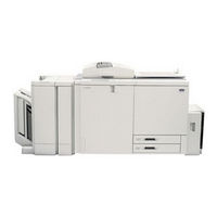
Canon 1000S Service Manual (840 pages)
color laser copier
Brand:
Canon
| Category:
Copier
| Size: 13.59 MB
Table of Contents
7
Table of Contents
6
System Configuration
13
Chapter 1 General Description
13
Features
14
Specifications
14
Type
14
Mechanisms
14
II. Specifications
15
Performance
17
Others
21
Laser and Safety Measures
21
Dhhs
21
Cdrh
22
Points to Note When Handling the Laser Unit
23
Names of Parts
23
External View
23
IV. Names of Parts
25
Cross Section
27
Control Panel
29
Chapter 2 Copying Process
29
I. Fixing (Step 7)
31
Image Formation
31
Outline
33
Static Latent Image Formation Block
33
Pre-Exposure (Step 1)
34
Primary Charging (Step 2)
34
Laser Exposure (Step 3)
35
Development (Step 4)
36
Retention/Transfer (Step 5)
37
Separation (Step 6)
37
Fixing (Step 7)
38
Photosensitive Drum Cleaning
39
Auxiliary Process
39
Pre-Primary Charging
39
Pre-Fixing Charging
40
Grounding Roller
40
Static Eliminator
41
Transfer Belt Cleaning
42
Limitations
42
Outline
42
Characteristics
43
Chapter 3 Operations and Timing
45
Basic Mechanisms
45
Functional Construction
46
Outline of Electrical Circuitry
47
Inputs to and Outputs From Major Pcbs
70
Sequence of Basic Operations
73
Original Exposure System
73
Outline
74
Sequence of Basic Operations (Original Exposure System)
76
Scanner Motor
77
Changing the Reproduction Ratio
78
Controlling the Intensity of the Scanning Lamp
79
Controlling the Intensity of the
80
Image Processing System
80
Outline
81
CCD/CCD Driver
82
Analog Image Processing
83
Digital Image Processing
99
Characteristics
106
Outline
106
Laser Exposure System
108
Sequence of Operations (Laser Exposure System)
109
Laser Scanner Motor
110
Generating the BD Signal
111
Outline
111
Video Controller
114
Density Correction
116
Laser Driver
118
Image Position Correction
128
Image Formation System
128
Outline
130
Basic Sequence of Operations (Image Formation System)
131
Stabilizing Images
141
Primary Charging Assembly
142
Controlling the Primary Corona Current
146
Developing Assembly
147
Controlling the Developing Bias
164
Cleaning the Photosensitive Drum
166
Controlling the Transfer Unit Charging Mechanism
171
Pick-Up/Feeding Assembly
171
Outline
174
Pick-Up Assembly
189
Paper Deck
195
Duplexing Unit
204
Transfer Unit
221
Pre-Fixing Feeding
222
Fixing/Delivery Assembly
224
Protection Mechanisms
233
Detecting Jams
236
VII. Control Panel
237
Chapter 4 MECHANICAL SYSTEM
237
Control Panel
239
VIII. Editor
241
Zero-Level Adjustment for Input Coordinates
242
Fans
245
Power Supply
245
Protection Mechanisms for the Power Supply Circuits
245
A. Power Supply
250
Table of Contents
255
I. Externals and Controls
257
Control Panel
257
Removing the Control Panel
258
Fans
258
Outline
258
Removing the Delivery Cooling
258
Fan (FM1/2/3)
258
Removing the Laser Cooling Fan (FM4/5)
259
Removing the Power Supply Cooling Fan (FM17/18)
260
Removing the Primary Exhaust Fan (FM6)
261
Primary Suction Fan (FM8/9)
261
Removing the Scanner Suction Fan (FM12/13)
262
Removing the Scanner Cooling Fan (FM10/11)
262
Removing the Digital Unit Cooling Fan (FM14/15/16)
263
Removing the Pre-Fixing Feeding Fan (FM7)
263
Removing the Delivery Assembly Lower Fan
264
Drive System
264
Drum Drive System
264
Removing the Drum Drive Assembly
264
II. Drive System
265
Developing Motor Assembly
265
Removing the Drum Motor Assembly
265
Points to Note When Installing the Drum Drive Belt
265
Removing the Developing Motor Assembly
266
Pick-Up Drive Assembly
266
Removing the Developing Motor
266
Outline
267
Removing the Pick-Up Drive Assembly
268
Removing the Pick-Up Motor
269
Scanner Drive Assembly
269
Removing the Scanner Drive Assembly/Scanner Motor
269
Adjusting the Belt Tension When Installing the Scanner Motor
269
Routing the Scanner Cable
272
Fixing Drive Assembly
272
Removing the Fixing Drive Assembly/Fixing Motor
273
Waste Toner Feeding Drive Assembly
273
Removing the Waste Toner
273
Feeding Drive Assembly/Waste
273
Toner Motor
274
Removing the Waste Toner Feeding Pipe/Screw
275
Pick-Up/Feeding System
275
Paper Deck
275
Removing the Paper Deck
275
Removing the Cover
276
Removing the Pick-Up Roller
276
Removing the Pick-Up/Feeding Roller
278
Removing the Separation Roller
280
Positioning the Pick-Up Roller Releasing Solenoid
280
Adjusting the Paper Surface
281
Pick-Up Assembly
281
Removing the Pick-Up Assembly
281
Removing the Pick-Up Roller
282
Removing the Feeding Roller
283
Removing the Pick-Up Assembly Separation Roller
284
Adjusting the Separation Roller Pressure
285
Positioning the Pick-Up Rollerreleasing Solenoid (SL9, SL10)
285
Releasing the Lifter
285
Left/Right Registration
286
Removing the Duplexing Pick-Up Roller
287
Removing the Duplexing Feeding Roller 1
287
Removing the Duplexing Feeding Roller 2
289
Multifeeder Assembly
289
Removing the Multifeeder Tray Assembly
289
Removing the Multifeeder Assembly
289
Removing the Multifeeder Assembly Pick-Up Roller
290
Removing the Multifeeder Assembly Feeding Roller/Separation Roller
290
Adjusting the Separation Roller
291
Duplexing Unit
291
Releasing the Lifter
291
Removing the Duplexing Unit
291
Removing the Duplexing Assembly Feeding Roller
292
Pre-Fixing Feeding Assembly
292
Pre-Duplexing Feeding Assembly
292
Removing the Pre-Fixing Feeding Assembly
292
Removing the Pre-Duplexing Feeding Assembly
294
Delivery/Reversing Assembly
294
Removing the Delivery/Reversing Assembly
294
Removing the Fixing Separation Claw
296
Transfer Unit
296
1A. Removing the Transfer Blade
296
IV. Transfer Unit
297
1B. Cleaning the Transfer Blade
297
Opening the Transfer Belt Assembly
299
Removing the Transfer Belt
303
Installing the Transfer Belt
304
Removing the Transfer Belt Assembly
304
Removing the Transfer Belt Swing Motor (M13)
305
Installing the Transfer Belt Motor
305
Removing the Internal Static Eliminating Roller
305
Removing the Transfer Belt Motor (M14)
306
Cleaning the Grounding Roller
306
Cleaning the Transfer Belt Seam Detecting Sticker
306
Removing the Grounding Roller
307
Transfer Belt Mount
307
Cleaning the Transfer Belt Home Position Sensor
307
Removing the Transfer Cleaning Blade
307
When Replacing the Transfer Cleaning Blade
308
Removing the Transfer Cleaning Web
308
Removing the Oil Removing Roller
308
Removing the Polishing Roller
309
Replacing the Separation Paper Guide Static Eliminating Wire
309
Replacing the Separation Paper
310
Exposure System
310
Original Exposure System
310
Removing the Scanning Lamp
310
Orientation of the Scanning Lamp
311
Removing the Standard White Plate
311
Removing the Lens Mount Cover, CCD Cover, and CCD Unit
312
Removing the Scanner Cover
313
Pre-Exposure System
313
Removing the Pre-Exposure System
314
Laser System
314
Laser Unit
314
Making Preparations for Laser Unit-Related Parts
315
Removing the Laser Unit
315
Points to Note When Installing the Laser Unit
317
Removing the Lens Scanner Motor (M4)
318
Image Position Correcting Mirror Unit
318
Removing the Y Image Position Correcting Mirror Unit
319
Points to Note When Installing the Y Image Correcting Mirror Unit
319
Removing and Installing the Motors for the Y Image Correcting Mirror
320
Shifting the Scanner Unit
322
Removing the M Image Position Correcting Mirror Unit
322
Removing the C/BK Image Position Correcting Mirror Unit
323
Removing the Dust-Proofing Glass
323
Removing the BD Unit
324
Hopper System
326
Hopper Assembly
326
Removing the Hopper Assembly
328
Keeping the Hopper Assembly From Tumbling Down
328
Removing the Hoppers
330
Removing the Toner Level Sensor
332
Charging System
332
Primary Charging Assembly
332
Outline
332
Removing the Primary Charging Assembly
332
Removing the Grid Plate
332
Removing the Primary Charging Assembly Cleaning Pad
333
Separation/Pre-Fixing Assembly
333
Removing the Separation/Pre-Fixing Assembly
333
Routing the Gut Wire
334
Process Unit System
334
Process Unit
334
Sliding Out the Process Unit
335
Removing the Developing Assembly/Cleaning Unit
337
Installing the Process Unit
339
Cleaning Assembly
339
Separating the Developing Assembly and the Cleaning Unit
339
Removing the Cleaning Blade
339
When Replacing the Cleaning Blade
340
Removing the Cleaner Side Seal
341
Developing Assembly
341
Removing the Cleaner End Seal
341
Removing the Cleaning Assembly Scope-Up Sheet
341
Cleaning the Developing
341
Assembly Upper Cover
342
Replacing the Color Toner Density
344
Photosensitive Drum
344
Removing the Photosensitive Drum
344
Cleaning the Photosensitive Drum
344
Points to Note When Installing the Photosensitive Drum
345
SALT Sensor
345
Removing the SALT Sensor
345
Cleaning the SALT Sensor Unit
346
Disassembling and Cleaning the Inside of the SALT Sensor Unit
347
No. 2 Scoop-Up Sheet
347
Removing the No. 2 Scoop-Up Sheet
348
Fixing System
348
Fixing Assembly
348
Removing the Fixing Assembly
349
Opening the Upper Fixing Roller Unit
350
Removing the Upper Fixing Heater
351
Removing the Lower Fixing Heater
351
Removing the Upper Fixing Roller
352
Removing the Lower Fixing Roller
352
Removing the Fixing Thermistor
352
(Upper) Method 1
353
Removing the Fixing Thermistor
353
(Upper) Method 2
353
Removing the Fixing Thermistor (Lower)
354
Removing the Fixing Thermal Switch (Upper)
355
Removing the Fixing Thermal Switch (Lower)
355
Removing the Oil Filter
355
Removing the Oil Bottle
356
Upper Fixing Cleaner Assembly
356
Removing the Upper Fixing Web
357
Fixing Lower Cleaning Assembly
357
Installing the Upper Fixing Web
357
Removing the Lower Fixing Web/Lower Fixing Blade
358
Removing the Lower Fixing Blade
359
Fixing Oil Application Unit
359
Installing the Lower Fixing Blade Mount
359
Removing the Oil Applying Roller Blade Unit
360
Removing the Oil Applying Roller Blade
360
Removing the Oil Applying Roller
360
Opening the Oil Applying Roller Assembly
361
Electrical System
361
Removing the DC Controller PCB
361
Removing the AC Driver
361
Removing the Lamp Regulator
362
Highvoltage Transformer
362
Removing the Developing Bias High-Voltage Transformer
363
Removing the Primary High-Voltage Transformer
363
Removing the DC Power Supply PCB
364
Removing the Environment Sensor PCB
364
Removing the Reader Controller
365
Removing the ECO Board
365
Removing the Analog Processor
366
Removing the Image Processor PCB and the Memory PCB
367
Removing the Video Controller PCB
367
Removing the Polygon Motor Driver
368
Removing the Potential Sensor Unit
369
Removing the Image Position
370
Cleaning the Shutter
370
Cleaning the LED
371
Removing the Transfer High-Voltage Transformer
373
Chapter 5 Installation
375
Selecting the Site
377
Installation
377
Unpacking
377
II. Installation
379
Removing the Fixings, Supplying Fixing Oil, and Changing the Voltage Rating (240V North American Model)
381
Supplying Toner
389
Supplying Starter
393
Externals
394
Mounting the Belt Retaining Members
395
Mounting the Developing Bias Assembly Protection Member
398
H-1.Installing the Paper Deck for CLC1000
405
H-2.Installing the Paper Deck-H1
407
H-3.Checking the Operation of the Paper Deck
409
Checking Images and Operations
410
Relocating the Machine
412
Installing the Original Tray
413
Installing the Control Card V
417
Chapter 6 Maintenance and Servicing
420
Periodically Replaced Parts
423
Consumables and Durables
423
By the Copier's Hard Counter
425
By the Soft Counter in Service Mode (COUNTER)
426
Scheduled Servicing Procedure
427
Scheduled Maintenance Chart
432
Table of Contents
437
Chapter 7 TROUBLESHOOTING IMAGE FAULTS/MALFUNCTIONS
437
Guide to Tables
439
Maintenance and Servicing
439
Image Adjustment Basic Procedure
441
Scheduled Servicing
443
Standards and Adjustments
443
Image-Related Parts
449
Original Illuminating System
452
Photosensitive Drum-Related Parts
454
Charging Assembly-Related Parts
455
Developing Assembly-Related Parts
459
Transfer Belt Unit
461
When Replacing the Pick-Up/Feeding-Related Parts
461
Registering the Cassette
463
Orientation of the Separation
464
Orientation of the Paper Deck
464
Pick-Up Roller
465
Releasing Solenoid (SL8001)
465
Adjusting the Pressure of the Paper Deck Separation/Feeding Roller
466
Adjusting the Pressure of the Separation Roller
466
Orientation of the Feeding Roller
467
Adjusting the Position of the
467
Releasing Solenoid
467
Adjusting the Pressure of the Multifeeder Separation Roller
467
Releasing Solenoid (SL5)
467
Duplexing Unit Pick-Up Roller
468
Adjusting the Position of the Delivery Paper Deflecting Plate Solenoid (SL14)
468
Adjusting the Position of the Duplexing Unit Paper Deflecting
468
Plate Solenoid (SL11)
468
Solenoid (SL12)
469
Duplexing Unit Stacking Assembly
469
Adjusting the Position of the Duplexing Unit Feeding Roller
469
Solenoid (SL13)
470
Attaching the Timing Belt for the Duplexing Unit Stacking Assembly Paper Guide Plate
470
Adjusting the Position of the Separation Claw Solenoid
470
(Sl15)
470
Solenoid (SL3)
471
Registration Roller Unit
471
Correcting Skew Movement (Slope of the Registration Roller Unit)
472
Laser Exposure System
472
When Replacing the Laser Unit
472
When Replacing the Video Controller PCB
472
When Replacing the BD Unit
472
Adjusting the Laser Power
475
Adjusting the Laser Intensity
476
Laser Focus Adjustment
477
Fixing Assembly-Related Parts
477
Points to Note When Replacing the Fixing Heater
477
Adjusting the Nip (Fixing Pressure Adjusting Nut)
478
Electrical ADJUSTMENT
478
When Replacing Major Parts
480
Checking the Environment Measurement PCB
481
Checking the High Voltage Control System
483
Checking the Photointerrupters
483
Using Service Mode
488
Troubleshooting Image Problems
488
Initial Checks
488
Checking the Site of Installation
488
Checking the Originals
488
Checking the Copyboard Cover, Copyboard Glass, and Standard White Plate
488
Checking the Charging Assemblies
489
Procedure
489
Others
489
Standard Image
489
Gray Scale
489
Color Patches
489
Photo
490
Fogging
492
Test Prints
492
Selecting a Test Pattern
493
Color Test Print (PGTYPE=02)
494
Gradation Test Print (PGTYPE=03)
494
Gradation Test Print
495
(Pgtype=04)
496
Halftone Test Print (PGTYPE=05)
497
Grid Test Print (PGTYPE=06)
498
Image Position Correction Pattern (PGTYPE=07)
499
Horizontal Stripe (FF Activation) Test Print (PGTYPE=10)
500
Full Color 17-Gradation (Ymcbk+Rgb+Gray) Test Print (PGTYPE=14)
500
Troubleshooting Image Faults
501
Troubleshooting Image Faults
501
The Image Is Too Light (All Colors)
501
The Image Is Too Light (Specific Color)
501
The Copy Has Uneven Density (Vertical)
503
The Copy Has Uneven Density (Horizontal)
504
The Copy Has Fogging
504
The Copy Has Vertical Streaks/ Vertical Lines
508
The Copy Has White Streaks/ White Lines (Vertical)
511
The Copy Has Horizontal Streaks/Horizontal Fogging
513
The Copy Has White Spots (Horizontal)
515
The Copy Has White Spots
516
The Copy Has White Spots
516
The Copy Has White Spots (Meandering)
516
The Copy Has a Soiled Image or Soiled Back
518
The Copy Has Poor Fixing
519
The Copy Has Bleeding Toner (During Fixing)
520
The Copy Is Blank
521
The Copy Is Solid Black
523
The Copy Has Color Displacement
524
Troubleshooting
524
Troubleshooting Malfunctions
524
E000/E004
526
E005
526
E006
527
E008
528
E012
529
E013
531
E014
532
E015
533
E017
533
E018
534
E020
539
E023
539
E030
540
E040
542
E041
543
E050
544
E061
546
E062
547
E070
548
E072
549
E073
549
E074
550
E075
551
E100
552
E110
553
E194
556
E208
556
E220
556
E350/E352
557
E351
557
E620
558
E633
559
E700
559
E800
560
AC Power Is Absent
561
DC Power Is Absent
562
The Scanner Fails to Move Forward/In Reverse
563
The Scanning Lamp Fails to Turn ON
564
The Lifter Fails to Move Up (Pick-Up From the Cassette)
565
Pick-Up Fails (Cassette 1)
566
Pick-Up Fails (Cassette 2)
567
The Multifeeder Fails to Pick Up Paper
567
The Registration Roller Fails to Rotate
568
Retention Fails
569
The Pre-Exposure Lamp Fails to Turn ON
570
The Fixing Heater Fails to Turn ON
572
The Drum Heater Fails to Rotate.7-136
573
The Counter Fails to Operate
574
The Cassette Heater Fails to Operate
575
Abnormal Noise Is Heard
576
Troubleshooting Feeding Problems
576
Jams
578
Pick-Up Assembly
579
Pick-Up Feeding Assembly
580
Transfer Unit Assembly
580
Separation/Pre-Fixing Feeding Assembly
581
Fixing/Delivery Assembly
582
Delivery Vertical Path, Duplexing Reversing Assembly, and Holding Tray Front Feeding Assembly
583
Duplexing Unit Stacking Assembly, Re-Pick-Up Assembly
584
Feeding Faults
584
Double Feeding
584
Wrinkles
585
Arrangement and Function of Electrical Parts
586
Sensors
592
Lamps, Switches, Thermistors, and Heaters
596
Clutches
598
Solenoids
600
Fans
602
Motors
604
Pcbs
606
Variable Resistors (VR), Light-Emitting Diodes (LED), and Check Pins By PCB
606
DC Controller PCB
607
Video Controller PCB
608
Reader Control PCB
609
Image Processor PCB
609
IP Memory PCB
610
Analog Processor PCB
611
Transfer Belt Motor Driver PCB
611
AC Driver PCB
612
Scanner Motor Driver PCB
612
Laser Driver PCB
614
Ip-Eco Pcb
614
Lamp Regulator PCB
615
Environment Sensor PCB
615
Hvt1
616
Hvt2
618
Hvt3
619
Hvt4
619
Hvt5
620
ED Board A1
621
Interface Board B1
622
Preview Monitor Board
623
Service Mode
623
Outline
623
Starting and Selecting Service Mode
623
Ending Service Mode
624
RAM Backup
626
Basic Operations
627
Control Display Mode (DISPLAY)
628
Version (ROM Version)
630
ACC-STS (Status of Option)
631
ANALOG (Measurement By Analog Sensor)
632
DENS (Developer Density)
635
EPOT (Photosensitive Drum Surface Potential Control Data)
636
SHD/BOF (Shading/Black Offset Data)
637
SENSOR (Sensor/DC Controller Input Port)
653
Jam/E Code
657
RF-INF (RDF State)
658
SORT-INF (SORT State)
659
BLT-DRFT (Belt Swing Data Display)
661
ADJUST (Adjustment)
662
ADJ-XY (Image Read Start Position Adjustment)
664
DOC-REC (Original Detection Area/Slice Level)
665
PROJ (Projector Area Adjustment)
667
Ed/Rdf
670
V-CONT (Photosensitive Drum Surface Potential Contrast Adjustment)
671
COL-ADJ (User Color Balance Adjustment Correction)
672
PASCAL (Auto Gradation Correction Control)
674
Adj-Misc
676
FEED-ADJ (Image Position Adjustment)
678
ENV-SET (Setting Operation Conditions for the Cassette Heater)
679
HV-TR (Transfer High-Voltage Output Adjustment By Condition)
681
HV-SP (Separation High-Voltage Output Fine-Adjustment By Condition)
683
HV-FS (Fine-Adjustment for Pre-Fixing High-Voltage Output According to Conditions)
685
HV-EL (Fine-Adjustment for Internal Static Eliminator High-Voltage Output According to Conditions)
687
FUNCTION (Function/Inspection)
688
INSTALL (At Time of Installation)
692
R-CON (Reader Controller Pcb-Related Adjustment)
693
DC-CON (DC Controller Pcb-Related Adjustment)
698
CCD (CCD-Related Adjustment)
700
PRJ-ADJ (Projector Adjustment)
701
LASER (Laser Adjustment)
702
P-UP-TMG (Pick-Up Timing Adjustment)
703
ATTRACT (Retention Position Adjustment)
704
EPC (Photosensitive Drum Potential Measurement)
705
BLADE (Transfer Blade/Transfer Belt Cleaning Blade Operation)
706
FUSER (Fixing Assembly-Related Adjustment)
707
CST-AD (Cassette Paper Width Adjustment)
708
F-Miscs (Reader-Related Operation/Inspection)
710
F-Miscp
718
TCLN (Polishing Roller/Oil Removing Roller Operation)
719
P-THICK (Paper Thickness Sensor Adjustment)
720
IMG-REG (Image Position Correction Control)
722
OPTION (Options Mode)
723
R-OPT (Reader-Related Machine Settings)
725
P-OPT (Cleaning Mode)
726
REMOTE (Machine Settings with IPU in Use)
727
DECK Settings for the Paper Deck
727
DATA-CON (Disconnecting the Copy Data Controller-A1)
728
TEST PRINT (Test Print)
730
COUNTER (Counter)
732
Self Diagnosis
732
VIII. Self Diagnosis
753
General Timing Chart
755
A. General Timing Chart
757
Signals and Abbreviations
765
C. General Circuit Diagram
767
General Circuit Diagram
769
Appendix
820
CCD Driver Circuit Diagram
824
Hvt Circuit Diagram
836
Special Tools
838
Solvents and Oils
769
DC Controller Circuit Diagram
Advertisement
Share and save
Advertisement
Related Products
Canon imageRUNNER 105
Canon CLC 1120
Canon 1160
Canon 1140
Canon imagePRESS 1125
Canon imagePRESS 1135
Canon 1530
Canon 1570F
Canon imagePRESS 1110
Canon imageRUNNER 1435
Canon Categories
Printer
Digital Camera
All in One Printer
Camcorder
Scanner
More Canon Manuals
Login
Sign In
OR
Sign in with Facebook
Sign in with Google
Upload manual
Upload from disk
Upload from URL