AUMA AC 01.2 Manuals
Manuals and User Guides for AUMA AC 01.2. We have 7 AUMA AC 01.2 manuals available for free PDF download: Manual, Operating Instructions Manual, Operation Instructions Manual

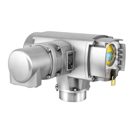
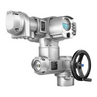
AUMA AC 01.2 Manual (160 pages)
Actuator controls
Brand: AUMA
|
Category: Control Unit
|
Size: 2 MB
Table of Contents
-
Operation
11 -
Indications
17 -
-
Operation
30 -
-
Contrast46
-
-
-
-
Local Stop87
-
Behaviour87
-
-
-
-
Motion Detector100
-
Delay Time101
-
-
Multiport Valve107
-
Dead Band112
-
Product Variants
107-
Factory Setting114
-
-
Data Export115
-
Data Import115
-
Firmware Update116
-
Service Software116
-
-
Diagnostics
118 -
Asset Management
125-
Operating Data125
-
Event Report126
-
Characteristics127
-
Histograms130
-
-
Appendix
143 -
Index
150 -
Parameter Index
154
Advertisement
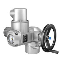
AUMA AC 01.2 Manual (148 pages)
Actuator controls
Brand: AUMA
|
Category: Control Unit
|
Size: 1 MB
Table of Contents
-
-
Name Plate10
-
-
3 Operation
13 -
-
Operation
32 -
-
Contrast45
-
-
-
-
-
Dead Band72
-
-
-
Local Stop88
-
Behaviour88
-
-
-
-
Enable Functions102
-
Factory Setting104
-
Diagnostics
108 -
-
Operating Data114
-
Event Report115
-
Characteristics116
-
Histograms119
-
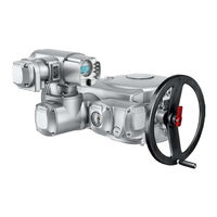
AUMA AC 01.2 Operating Instructions Manual (104 pages)
Multi-turn actuators, Control unit: electronic MWG with actuator controls, Non-Intrusive
Brand: AUMA
|
Category: Controller
|
Size: 3 MB
Table of Contents
-
4 Assembly
15 -
-
Operation
44 -
Indications
52 -
-
Test Run66
-
Advertisement
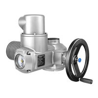
AUMA AC 01.2 Operating Instructions Manual (104 pages)
Multi-turn actuators
Brand: AUMA
|
Category: Controller
|
Size: 2 MB
Table of Contents
-
4 Assembly
16 -
-
Operation
39 -
Indications
47 -
-
Test Run63
-
AUMA AC 01.2 Operation Instructions Manual (96 pages)
Part-turn actuators
Brand: AUMA
|
Category: Controller
|
Size: 2 MB
Table of Contents
-
4 Assembly
15 -
-
Operation
33 -
Indications
40 -
-
Test Run57

AUMA AC 01.2 Operation Instructions Manual (96 pages)
Multi-turn actuators Control unit - electromechanical with actuator controls
Brand: AUMA
|
Category: Controller
|
Size: 2 MB
Table of Contents
-
5 Assembly
16 -
-
Operation
38 -
Indications
46 -
-
Test Run59
AUMA AC 01.2 Manual (44 pages)
Brand: AUMA
|
Category: Controller
|
Size: 2 MB
Table of Contents
-
-
Installation16
-
Operation18
-
Lifetime18
-
-
Indications
20 -
Signals
21 -
-
Maintenance27
-
Checklists
33
Advertisement